Programming abstractions and middleware for building control systems as networks of ... Many smart components in the automotive and also automation indus-.
Programming abstractions and middleware for building control systems as networks of smart sensors and actuators Sebastian Zug, Michael Schulze, Andr´e Dietrich, J¨org Kaiser Universit¨at Magdeburg Department for Distributed Systems Universit¨atsplatz 2, 39106 Magdeburg, Germany {zug, schulze, dietrich, kaiser}@ivs.cs.uni-magdeburg.de
Abstract Developing complex sensor/actuator systems, like robot applications, is challenged by a multitude of different hardware platforms, networks, programming languages, data formats, etc. In this paper, we present our architecture that copes with this heterogeneity and allows for a flexible composition of smart sensors and actuators. The main focus lies on a two layered approach combining the communication middleware FAMOUSO and the programming abstraction MOSAIC. FAMOUSO enables the information exchange between networked systems, hides the high degree of heterogeneity on hardware and network level, and is usable from different programming environments. MOSAIC uses FAMOUSO and provides a generic access to the exchanged information. Furthermore, it offers a way to abstract from different sensor and actuator hardware and provides a framework for application development with predefined components, enabling comprehensive fault detection. The paper concludes with a case study that shows how the middleware and programming abstractions are used to build a distributed modular system for a robot manipulator.
1
Introduction
Networked components like smart sensors, actuators and special computational devices emerge as the hardware building blocks for large scale automation systems. They offer the potential to build such control systems in a modular and incremental way or even allow dynamic extension of the system when mobile units connect to fixed environmental sensors spontaneously. Unfortunately, many problems have to be solved on the way to a reliable, seamlessly integrated system that is easy to program, easy to extend and easy to maintain. One problem originates in the high degree of heterogeneity on all system levels that adversely affects integration. The diversity appears not only on the lower system levels, i.e. different controllers, field-busses, proto-
cols and operating systems, but also on the level of programming languages and domain specific tools to program, monitor and maintain these systems. Changes of the system configuration (e.g. replacement of a component) or low level changes in one component (e.g., a network address) may involve a chain of dependent changes in other components which may require specific tools and tedious reprogramming of flash memory. This kind of heterogeneity problem can be tackled by an adequate communication model and middleware that hides the network addressing schemes and offers a content- or subject-based routing scheme. We assume that the individual smart components have substantial resource constraints. Many smart components in the automotive and also automation industry are based on 8 or 16-Bit CPUs and the communication networks have limited bandwidth. Thus, the middleware must be able to work on these systems. A second problem is the diversity of sensors with many different modalities and data formats. This can be solved by a standard that must cover a wide range of possible sensors from simple temperature sensors to cameras. The usual way to achieve this is defining a standard description of a sensor in the form of electronic data sheets, like in [11, 17], but modifications and extensions are needed, as we describe later. Moreover, defining a structured programming model and a general interface simplifies the implementation of sensor components, greatly. The third problem is related to the structure of a sensor and addresses reliability issues. Assuming a decentralized system of sensors and actuators connected by wired and wireless networks, an indication of correctness of information is important. Firstly, the compatibility of information like physical units and the temporal settings during the system integration and configuration phases must ensured. We tackle this problem with expressive descriptions of components and endowing the compiler and integration tools with the respective checking capabilities [28]. The second aspect is related to the assessment of the quality of individual sensor measurements during run-time. This requires self-checking capabilities of the components. The proposed sensor structure exploits
model-based analytic redundancy and comprises building blocks for the detection of outliers and other typical sensor faults [9]. This paper gives an overview of our architecture, describes the middleware and the sensor structure, and presents a case study of a robot application that includes many sensors, actuators, networks, and monitoring and visualization components. The contribution of the paper is to show the problems when integrating such a system and how the developed concepts and mechanisms ease programming of such systems and system integration. In the next section we survey related work in the relevant areas. Then we sketch the main properties of the middleware FAMOUSO and briefly present the sensor model MOSAIC. Section 4 introduces the case study and highlights the benefits of the proposed architecture. A summary and outlook on ongoing work concludes the paper.
2
the software level with components or services. Systems like OROCOS (Open RObot Control Software www. orocos.org), OCERA (Open Components for Embedded Real-time Applications www.ocera.org) or Microsoft RoboticStudio [21] fall into this category. OROCOS and OCERA are component systems, using a CORBA-DDS implementation for the information exchange of distributed applications. However, integrating low-level components connected via an industrial fieldbus the communication model is different, and applications have to know where information are located and realize the access to such a bus by itself to get the required information, which makes the development uncomfortable. In contrast to the component approach, the Microsoft RoboticStudio uses a service-oriented architecture, which supports the simulation of robot behavior in a virtual environment, based on realistic physical models that reproduce the mechanical behavior and offers the simulation of most common sensors and actuators. Furthermore, it allows applying the same control schemes to real hardware. However, the disadvantage is the high resource requirements, because it uses TCP/IP for the communication and needs a whole .NET framework to be worked.
Related Work
The related work section examines two main fields that are challenging when integrating networks of smart components. Firstly, we need appropriate middleware that enables communication across different kinds of networks, covering the field-bus level and energy-efficient wireless protocols. This middleware must run on different hardware platforms down to small micro-controllers. Secondly, we require a programming abstraction that offers a uniform access to the exchanged information and a predefined processing structure, utilizing this common interface. In the following section we examine existing approaches with respect to our general requirements.
Sensor Network Middleware For Wireless Sensor Networks (WSNs) only few middleware systems are available, like MIRES [30] supporting publish/subscribe communication or TinyLIME [7] providing a tuple space. Using these middleware systems means to be tied to the component model of TinyOS [16], because both are developed on top of this. Furthermore, applications have to be programmed in NesC, the programming language of TinyOS, which means on the one hand the developer can not use its preferred tools and on the other hand it needs to learn a new language. However, the main drawback of using the mentioned systems is the lack of support of TinyOS for different platforms, because at the moment of this writing only three different CPUs are supported.
2.1 Communication Approaches Internet Scale Middleware SIENA [6], HERMES [25] or READY [12] are publish/subscribe systems, based on a static broker overlay network with reliable TCP/IP connections. Thus, these systems support information exchange for distributed application, but they demand a standard operating system like Linux or Windows, requiring powerful devices. The Network Data Distribution Service NDDS [24] or the ACE ORB (TAO [13]) are publish/subscribe systems, which support many platforms and also offer soft realtime features. However, the communication is based on UDP/IP, having also requiring powerful devices. In general, traditional middleware systems such as DCOM (Distributed Component Object Model [10]), JMS (Java Messaging Service [31]) or CORBA-DDS (Common Object Request Broker Architecture-Data Distribution Service [23]) are normally heavyweight in terms of memory and computation and therefore not suitable for the use on resource-constrained embedded systems.
2.2 Programming Abstraction Approaches Instrumented Logical Sensor Henderson et al. proposed hierarchically applicable fusion/filter units, called Logical Sensors or Instrumented Logical Sensors [14] and developed a complete toolchain with a sensor description, configuration, and code generation. Henderson’s approach focuses on an adaptability of each Logical Sensor to a varying number of incoming data. A sensor selection mechanism manages the data acquisition for this purpose and tries to compensate missing individual sensor measurements or network inputs. The Logical Sensor integrates network interfaces only. Real transducers and their drivers are executed separately in a special gateway instance of a Logical Sensor. The characteristic output vector, defined for each Logical Sensor, does not consider several aspects of sensor applications like perception uncertainties, units of measurement, etc. necessary for a tailored processing or fusion.
Robotic Middleware In the robotic field, middleware systems have been developed that try to ease the development by composing the robot’s control system at 2
Fusion Channels The fundamental abstraction of the architecture described by Agarwalla et al. in [26] is called a Fusion Channel (FC). A FC abstracts a set of inputs and encapsulates a programmer defined fusion function. The inputs are obtained from a distinct address space or from a remote host. The behavior of the fusion process is controllable by requests to the FC or triggered in case of new input data. Applications access the FC result in two ways: as a single value with a timestamps or the whole FC output buffer. Requests specify a minimum number of inputs and a timeout to get a result. Further, FC may be organized in hierarchical structures. The FC approach does not consider an abstract description of the exchanged information. The developer, who prepares a fusion application running inside a FC, has to have an explicit knowledge of the memory usage. An implementation of the FC concept in the Dfuse framework [19] requires a complex predefined infrastructure and uses Ethernet based protocols only.
IEEE 1451.2 defines an electronic data sheet and a digital sensor interface to access sensor measurements, set actuators, control maintenance functions, or to obtain the data sheet of the sensor/actuator system. Hence, the standard establishes the communication between a Network Capable Application Processor (NCAP) and an actual sensor node called Smart Transducer Interface Modules (STIM). The combination enables a flexible access to different networks via special NCAP gateways. The standards 1451.3 to 1451.5 enhance the interaction between STIMs and NCAPs to various protocols and interfaces. The description of the sensors, stored at each node, contains a detailed specification of the sensor’s vendor, firmware, and physics in a compressed Transducer Electronic Data Sheets (TEDs). TEDs do not support complex sensor information like characteristic curves for linearization or probability functions of sensor’s noise. The use in realistic sensor scenarios without this information is quite limited. Compared to other mentioned approaches IEEE 1451 represents an abstract description of the sensors interfaces only, which have to be mapped to a predefined number of sensor types. In [18] the authors use some concepts of the standard to develop a more common programming abstraction with middleware interactions but restricted to simple sensor models.
Virtual Sensors The traditional Virtual Sensor merges several measurements into a joint estimation, quite often based on a physical model as presented in [2] . In contrast, Bose et al. [4] describe a programming abstraction for distributed applications and defines a number of subclasses for different purposes of hierarchical ordering. The first level, the Singleton Virtual Sensor (SVS), accepts only individual measurements and assigns sensor position, sensor ID, etc. A Basic Virtual Sensor (BVS) combines multiple SVSs of the same type and provides a better reliability. A Derived Virtual Sensor integrates different BVSs and provides abstract SQL queries to raw and joint data. In case of crashed Virtual Sensors the network structure is reconfigured automatically. The reconfiguration mechanism limits the Virtual Sensors to simple sensor assumption about sensor specifications i. e., equal measurement noise, equal range, etc. for all sensors. Additionally, Virtual Sensor applications are limited to a hierarchical depth of three nodes, according to the definition of the three subclasses.
2.3 Conclusion The described middleware implementations are usable in their specific contexts. They support special types of networks and protocols and are either limited in scope and functionality when supporting small devices or they require very powerful nodes. None of the enumerated abstractions, standards, etc. fully meets our expectations for a unified programming abstraction for sensors and actuators that considers varying configurations with a common interface access and are executable on performance limited devices. Moreover, the related schemes do not provide integrated fault-tolerance mechanisms.
3
Smart Transducer Interface (STI) The OMG Smart Transducer Interface Specification [22] provides an access to sensor measurements via the CORBA real-time service interface. The standardization of the different interfaces is mapped on an interface file system (IFS) typically in the memory of each Smart Transducer. For an interpretation of the outputs an additional metadata for each IFS are stored on a central node with higher performance. The integration of CORBA limits the implementation of the STI approach to powerful CPUs. The authors of [11] enhanced the STI concept and developed an XML description of the functionality for simple fusion tasks, also offering a TTP/A network support.
Architecture
We propose an architecture, providing the flexibility to integrate and segregate components during run-time, dynamically. For this purpose we combine a communication middleware and a programming abstraction for distributed applications. The middleware organizes the transmission of all necessary information, while the programming abstraction is responsible for an adequate filtering, selection, fusion, and validation. 3.1 Communication – FAMOUSO Our middleware FAMOUSO (Family of Adaptive Middleware for autonomOUs Sentient Objects [15, 27, 29]) provides an event-based communication over different network types, according to the publisher/subscriber paradigm. In contrast to an address-based communication, an anonymous content-based communication is used,
IEEE 1451 The Smart Transducer Interface represents a family of standards for connecting smart devices [17]. 3
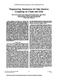
where events are exchanged between communication endpoints. Publishers as well as subscribers are roles that applications have during the communication. Related to its characteristic as publisher, subscriber, or both, applications specify the kind of events they produce or consume. On that simple scheme, FAMOUSO provides spontaneous and dynamic many-to-many communication without any assumptions about synchrony of events. The communication is always asynchronous, avoiding control flow dependencies and enabling the autonomy of communication participants. The exchanged information – FAMOUSO events – consists of three parts: a subject, optional attributes, and content. Optional attributes could be context attributes, which deliver additional information about the origin of the event like location or timestamp. Subjects are defined by the applications, and they build a global address space, spanning across all networks. This feature is exploited by gateways that enable and manage communication between different networks. The uniqueness of subjects is used firstly to filter the information flow on network borders if a subject is only required within a specific subnet, and secondly to perform forwarding if the subject is subscribed outside. From the perspective of most applications, the definition of events and its use should be sufficient. However, in the embedded field, applications have often quality of service (QoS) demands regarding real-time or dependability issues. These demands have repercussions to the underlying support system, because the system has to ensure and enforce given guarantees. To tackle that challenge, FAMOUSO has the notion of event channel, which is used firstly as an abstraction for event disseminations, secondly for the specification of dissemination requirements like deadline, jitter, omission degree, etc., and thirdly for reserving the needed local as well as network resources to enforce the given guarantees if possible. Further, FAMOUSO supports with its Multi-Level Composability Check Architecture (MLCCA [28]) an integrated component that detects a misconfiguration or an unrealizable application demand as early as possible. If an event channel is correctly setup, events can be transferred through this event channel to its destinations, if the subject of the event corresponds to that from the channel. FAMOUSO is realized as a layered architecture. The number of layers depends on the selected middleware configuration, but FAMOUSO has usually three layers, as depicted schematically in Figure 1. The number of layers grows in case of complex configurations for e. g., gateways due to the need to integrate the respective functionality into the infrastructure. On each layer certain functionality is implemented, and the abstraction level increases from the concrete network layer up to the event layer, which provides the publisher/subscriber interface. Applications get and use, independently of the actual configuration of the middleware, only this interface. The different layers offer special functionalities. On
Application Layer C/C++ Java MATLAB/Simulink
LabVIEW Python
.NET Publish/Subscribe Interface Event Layer Resource ECH Management
event
Abstract Network Layer Fragmentation HRT-ECH Protocol
message
Concrete Network Layer Binding Configuration Protocol Protocol
network specific packet
Ethernet
CAN
Wireless
Figure 1. Schematic view on the layered architecture of FAMOUSO
the Event Layer level, the event channels are managed by the Event Channel Handler (ECH). The ECH takes care about necessary resources, and observes the guaranteed QoS parameters at run-time. For example, if an application specifies a period of 50ms for incoming events on an event channel, and within the last 50ms no event arises, leading to a specification violation, the middleware calls an error-handler callback for this event channel. The callback mechanism of the middleware permits indicating specification violations, enabling applications to be aware of violations, and thus reacting accordingly for example with a fail-safe state or with adaptation. The following layer, which is the Abstract Network Layer, is responsible for functionality that can be realized independently of specific network characteristics and thus made available for several networks. One example is the adaptive fragmentation protocol, which enables transferring large events over networks that are not able to send such events as a whole. Furthermore, the layer provides the real-time communication mechanisms for events that are termed as messages here. The Concrete Network Layer (CNL), the lowest layer, encapsulates all this functionality that is absolutely specific for the respective network, because networks differ in a lot of ways (e. g., address scheme and message format) and a generalization of all functionality is not possible. Firstly, the CNL contains the binding protocol, which is responsible for binding the subject to a specific network representation, because this totally differs between CAN or Ethernet, and secondly, the configuration protocol configures the node to give it a unique network name. To ensure the compliance of the network protocol character4
istics, the protocols exist in specialized versions for each supported network and they are part of the respective network layer realization, which supports the upper layers with functionality for the communication. FAMOUSO supports a broad variety of different hardware platforms ranging from low-end 8-Bit microcontrollers up to high-end 64-Bit server systems and enables interaction over different communication media like the CANfield-bus, Wireless Sensor Networks (WSN) like IEEE 802.15.4,Wireless Mesh Networks like AWDS [3], and Ethernet like UDP broad- and multicast (Figure 1). FAMOUSO can be used from different programming languages (C/C++, Python, Java, .NET) as well as from engineering tools (LabVIEW, MATLAB/Simulink) simultaneously. Thus, the middleware enables the developers to individually choose their preferred combination of tools and languages. Objectives of FAMOUSO are configurability, adaptability, portability, and efficient resource usage to allow also the deployment on small resource-constrained embedded devices.
Sensor(s)
Fault Detection
Abstract Sensor Interface Application Outlier Fault Detection FAMOUSO Detection Validity Calculation
Statistical Check
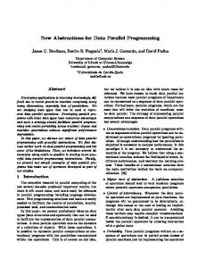
Abstract Network Interface Pub/Sub Figure 2. Smart Abstract Sensor Structure
types in general. The first one organizes the access to data contained in FAMOUSO events, arranges and buffers the data according to application requirements and collects fault notifications from FAMOUSO (for instance due to the absence of periodic events). The knowledge about the data format of events is located within an XML electronic data sheet for each FAMOUSO event channel. This XML-document contains all information that are necessary to interpret an incoming event correctly (data types, attributes, units, uncertainties, etc.) and to supervise the channel (deadlines, periods, and omissions). The second interface of a Smart Abstract Entity depicted in the upper part of Figure 2 is responsible for the communication with sensor and actuator hardware, and furthermore linearizes and transforms sensor measurements (e. g., voltage from ADC into degree Celsius for temperature sensors). We used the same approach again and developed an XML description that contains sensor and hardware specific properties and embed them into a toolchain for Abstract Entities based on MATLAB/Simulink [5]. In combination with the FAMOUSO event channel descriptions, the developer obtains an application framework that includes both abstract interfaces. The specific configuration of sensor interfaces is encapsulated in the model generation process. Thus, the engineer focuses on the application development, uses domain specific development tools, and does not need not to cope with communication mechanisms nor hardware implementation. A predefined application structure is important to enable fault detection mechanisms in all components, because it is a cross cutting concern. We enhanced the existing idea of Smart Sensors with the fault-tolerance aspect. Each component of the application framework calculates a fault probability that is merged in a fault detection component and assigned to each generated event at the end. Therefore, we analyzed the faults of distributed sensor and actuator applications and discussed possible detection methods and derived a modular structure for Smart Abstract Sensors in [9]. Besides, the flexible communi-
3.2 MOSAIC A programming abstraction for distributed applications should offer three core elements: firstly, it needs a generic access to the exchanged information and an abstract interface to sensors/actuators. Secondly, it should provide a modular structure for applications, because such a predefined modular structure allows a flexible replaceability of inner components and enables a comprehensive fault detection and classification as the third important property. Based on these requirements we developed our fraMework for fault-tOlerant Sensor dAta processIng in dynamiC environments (MOSAIC) that defines an appropriate programming abstraction – the “Smart Abstract Entity”. This approach extends and combines the concept of preprocessed and self describing measurements done by Smart Sensors in combination with the Abstract Sensor concept of Marzullo [20]. Due to the flexible composability and in relation to the different purposes of Smart Abstract Entities, we distinguish between three variants that can be combined in distributed applications: the first one, the Smart Abstract Sensor, visible in Figure 2, uses one or more real transducers to perceive the environment and communicates the measurements after filtering and validation tasks. In contrast to this variant, the second one is the Smart Abstract Actuator, which controls a mechatronic device based on the information obtained form the communication interface. The Smart Abstract Fusion Node does neither include sensors nor actuators and uses the communication interface only. Such entities are used for measurement fusion and processing, simulated sensors, etc. In Figure 2 we depict the basic building blocks of a Smart Abstract Sensor. Except for the actuator output interface, Smart Abstract Actuators are structured very similarly to Smart Abstract Sensors. From the application point of view we have to cope with two interface 5
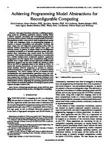
Enhanced System Basic System
Safety Extension
AVR (C++)
PowerPC (C++)
PC (Python)
PC (MATLAB)
PC (C++)
Distance Sensor
Robot Control
Virtual Sensor
Path Calc
Visualisation
FAMOUSO CAN
CAN Ethernet
Figure 3. Scenario structure combining FAMOUSO and MOSAIC cation infrastructure enables new fault-tolerance methods for Smart Abstract Sensors. Each Smart Abstract Sensor is subscribed to the fusion result that is potentially available. This feedback offers redundant information and enables an efficient validation of the current measurement. As shown in this section, we continued the layered architecture of FAMOUSO in our programming abstraction, reduced the integration effort for sensors and communication interfaces, and presented a comprehensive programming abstraction for distributed applications.
4
nario and illustrates the diversity of components, programming languages, and underlying communication networks. Due to the FAMOUSO middleware and MOSAIC all components can be easily integrated or segregated without much effort. Implementing the scenario without the support of FAMOUSO and MOSAIC is possible, however, it means implementing the low-level access to a CAN network “Basic System” and accessing a UDP network from three different programming languages. The data exchange between the CAN and UDP network is also in the responsibility of the developer, but using FAMOUSO gateways (not depicted in Figure 3) are an integral part of the infrastructure. In the same way an implementation may be done without fault-tolerance mechanisms and individual data formats instead of generalized definitions in electronic data sheets. However, the effort to establish a dynamic configurable and maintainable application increases significantly and error-proneness grows.
Scenario
Using our layered FAMOUSO/MOSAIC architecture throughout the system allows to setup distributed applications easily. Furthermore, applications may be enhanced by adding components dynamically and without any need to change application code of other running system components. In industrial environments for example, a high level plant asset management system subscribes to information of different production lines for monitoring or even control purposes. On a lower system level, additional sensors can be integrated to extend the sensor-based perception area of the environment. We present a scenario that serves as a typical example to emphasize the benefits of our approach by showing aspects like modularity and dynamic composability. As a physical actuator, we use a robot manipulator that is equipped with a limited number of real distance sensors, observing the near environment. The manipulator follows a pre-calculated trajectory and stops in case of a detected obstacle. Next, we integrate a safety extension, which allows for adding e. g. virtual walls dynamically, in order to restrict the manipulator’s working area for safety reasons. Furthermore, we use this example setup in the development phase of reliable and maintainable robot applications as well as when exploring extended human-robot interaction schemes. Figure 3 presents the schematic structure of the sce-
4.1 Basic System The basic robot application consists of two elements that are connected via CAN. These are a PowerPC, in the role of a Smart Abstract Actuator, and a Smart Abstract Distance Sensor that is controlled by an AVR AT90CAN128, both programmed in C++. The AVR publishes events, periodically. Events contain a distance measurement, the related validity value, and respective sensor failure/error modes. The PowerPC is responsible for controlling the Katanta robot, a five degrees of freedom manipulator. This Robot Control publishes status data (e. g., angles of robot’s axes, different modes, and present current) and subscribes to control commands for movement, speed, and emergency stop. 4.2 Safety System The basic system may be enhanced by a safety system without changing anything at the base system. As shown in Figure 3, we integrate a safety system consisting of two additional PCs that are connected to the Ethernet. A 6
FAMOUSO gateway connects both networks and ensures that events are routed to the interested participants. One of the additional components, a Virtual Sensor, is implemented in Python, and it publishes distance values. These distance values are calculated from the robot’s distance to some virtual walls. In this way it is possible to define virtual safety areas the robot is not allowed to leave. The only data that is required by the Virtual Sensor here are the angles of robot’s axes. The second component, the Path Calculation is realized on a separate PC and is implemented in MATLAB. The manipulator’s trajectory is calculated depending on all available sensor distance data – real or virtual – as well as to the values and states of the robot’s axes. A path is composed by multiple stages that are published sequentially in form of axes values. A new stage is transmitted when the robot reaches a target position. If the robot is unable to reach its target position due to a detected obstacle, another path will be calculated and published.
Figure 4. Visualization for engineers, presenting the current sensor output
experimental system to acquire experience. This includes for example sensor data (subscription to Virtual Sensor and Distance Sensor), robot’s states and position of axes (subscription to Robot Control). While in this case it is also appropriate to use colors, color transitions or transparency to visualize additional information like uncertainties, ranges, or the age of sensor data. Additional information like diagrams or robot’s contour can be placed onto display as well.
4.3 Visualization As a third part of our scenario, we add a Visualization, again without any adaptation of other components of the original system at all. This application is for supporting factory workers, developers, and maintenance workers by using the technique of Augmented Reality, which presents an enhanced visual representation of a work space. The realization of the Visualization uses ARToolKit [1] and OpenGL to overlay real world camera images with additional information. A detailed description of the benefits of using Augmented Reality to support different kinds of users in industrial application is beyond the scope of this paper and can be found in [8]. The Visualization component subscribes to different information (e. g., axes positions, sensor measurements, stages of path calculation) according to user requirements and presents the information in an appropriate manner. For visualizing the information perspectively correct, Augmented Reality needs to match the real and virtual images. The ARToolKit uses marker-based object identification, and information is relatively drawn to the detected markers. The screenshot taken from an ordinary monitor in Figure 4 shows such an Augmented Reality in operation. It depicts for example a view for a developer, which differs completely from the view that a factory worker would need to interact with the robot. For these scenarios and applications head-mounted displays will be more appropriate than monitors, however the application can be adapted very easily to these more advanced devices. A factory worker requires a proper graphical representation of safety areas (subscription to Virtual Sensor), robot’s future trajectories (subscription to Path Calculation), or a graphical representation of robot’s states (subscription to Robot Control). The visualization for developers like in our scenario can be more complex to enable playing around with the
5
Conclusions and Outlook
MOSAIC and FAMOUSO ease the development of extensible, distributed and modular applications across different platforms and networks. We demonstrated the benefits in a robotic scenario. The communication middleware enables a dynamic composition during development process, configuration and even on run-time for system upgrades. FAMOUSO supports domain specific languages and flexible and seamless integration of distributed hardware and software modules. This opens an easy way for Hardware-/Software-in-the-Loop test scenarios. To address the specific problems of correct sensor information in a decentralized and dynamic scenario, MOSAIC establishes a generic smart component structure and interface. Next steps will include improvement of the code generation process for constrained platforms, integration of multilevel compliance checks based on our XML descriptions and extended detection mechanisms for faults, typical for smart distributed sensors.
Acknowledgement This work is partly founded by the Ministry of Education and Science (BMBF) within the project “Virtual and Augmented Reality for Highly Safety and Reliable Embedded Systems” (ViERforES - no. 01IM08003C). 7
References
[17] IEEE Standards Association. IEEE Standard for a Smart Transducer Interface for Sensors and Actuators (IEEE 1451.2), 1997. [18] J. Kaiser and H. Piontek. CODES: Supporting the development process in a publish/subscribe system. In Proceedings of the fourth Workshop on Intelligent Solutions in Embedded Systems WISES 06, pages 1–12, Vienna, 30. June 2006. ISBN: 3-902463-06-6. [19] R. Kumar, M. Wolenetz, B. Agarwalla, J. Shin, P. Hutto, A. Paul, and U. Ramachandran. Dfuse: a framework for distributed data fusion. In Proceedings of the 1st international conference on Embedded networked sensor systems, pages 114–125, Los Angeles, California, USA, 2003. ACM. [20] K. Marzullo. Tolerating Failures of Continuous-Valued Sensors. ACM Transactions on Computer Systems (TOCS), 8(4):284–304, November 1990. [21] Microsoft Corporation . Microsoft robotics studio. online, http://msdn.microsoft.com/ en-gb/library/bb881626.aspx. [22] Object Managment Group (OMG). Smart Transducer INterface Specification, 2003. [23] OMG. Data Distribution Service for Real-time Systems Version 1.2. Object Managment Group, 1. January 2007. [24] G. Pardo-Castellote and S. A. Schneider. The Network Data Delivery Service: Real-Time Data Connectivity for Distributed Control Applications. In Proceedings of the ICRA, volume 4, pages 2870–2876, San Diego, CA, USA, May 1994. IEEE Computer Society Press. [25] P. R. Pietzuch and J. Bacon. Hermes: A Distributed EventBased Middleware Architecture. In ICDCSW ’02: Proceedings of the 22nd International Conference on Distributed Computing Systems, pages 611–618, Washington, DC, USA, 2002. IEEE Computer Society. [26] U. Ramachandran, R. Kumar, M. Wolenetz, B. Cooper, B. Agarwalla, J. Shin, P. Hutto, and A. Paul. Dynamic Data Fusion for Future Sensor Networks. ACM Transactions on Sensor Networks (TOSN), 2(3):404–443, 2006. [27] M. Schulze. FAMOUSO – Eine adaptierbare Publish/ Subscribe Middleware f¨ur ressourcenbeschr¨ankte Systeme. Electronic Communications of the EASST (ISSN: 18632122), 17, 2009. [28] M. Schulze and G. Lukas. MLCCA – Multi-Level Composability Check Architecture for Dependable Communication over Heterogeneous Networks. In Procedings of 14th International Conference on Emerging Technologies and Factory Automation, Mallorca, Spain, 22-26 Septmeber 2009. IEEE. [29] M. Schulze and S. Zug. Exploiting the FAMOUSO Middleware in Multi-Robot Application Development with Matlab/Simulink. In Proceedings of the ACM/IFIP/USENIX Middleware ’08 Conference Companion, pages 74–77, Leuven, Belgium, 1-5 December 2008. ACM. [30] E. Souto, a. Germano Guimar G. Vasconcelos, M. Vieira, N. Rosa, and C. Ferraz. A Message-Oriented Middleware for Sensor Networks. In MPAC ’04: Proceedings of the 2nd workshop on Middleware for pervasive and adhoc computing, volume 77 of ACM International Conference Proceeding Series, pages 127–134, Toronto, Ontario, Canada, 2004. ACM. [31] Sun Microsystems, Inc. Java Message Service (JMS) Specification 1.0.2, 1999.
[1] Artoolkit. http://www.hitl.washington.edu/ artoolkit/, 2007. [(online), as at: 25.02. 2010]. [2] P. Albertos and G. Goodwin. Virtual sensors for control applications. Annual Reviews in Control, 26(1):101–112, 2002. [3] AWDS project. http://awds.berlios.de, 2009. [4] R. Bose, A. Helal, V. Sivakumar, and S. Lim. Virtual sensors for service oriented intelligent environments. In Proceedings of the third conference on IASTED International Conference: Advances in Computer Science and Technology, pages 165–170, Phuket, Thailand, 2007. ACTA Press. [5] T. Brade, M. Schulze, S. Zug, and J. Kaiser. Model-Driven development of embedded systems. In 12th Brazilian Workshop on Real-Time and Embedded Systems (WTR), Gramado, Brazil, 24 May 2010. Brazilian Computer Society. [6] A. Carzaniga, D. S. Rosenblum, and A. L. Wolf. Design and Evaluation of a Wide-Area Event Notification Service. ACM Trans. Comput. Syst., 19(3):332–383, 2001. [7] C. Curino, M. Giani, M. Giorgetta, A. Giusti, A. Murphy, and G. Picco. TinyLIME: Bridging Mobile and Sensor Networks through Middleware. In Third IEEE International Conference on Pervasive Computing and Communications, pages 61–72, Kauai Island, HI, USA, March 2005. [8] A. Dietrich, M. Schulze, S. Zug, and J. Kaiser. Visualization of Robot’s Awareness and Perception. In First International Workshop on Digital Engineering (IWDE), Magdeburg, Germany, 14 June 2010. [9] A. Dietrich, S. Zug, and J. Kaiser. Detecting external measurement disturbances based on statistical analysis for smart sensors. In Procedings of the IEEE International Symposium on Industrial Electronics (ISIE), 2010. [10] G. Eddon and H. Eddon. Inside Distributed COM. Microsoft Press, 1998. ISBN 1-57231-849-x. [11] W. Elmenreich, S. Pitzek, and M. Schlager. Modeling Distributed Embedded Applications on an Interface File System. In Proceedings of the Seventh IEEE International Symposium on Object-Oriented Real-Time Distributed Computing (ISORC’04), pages 175–182, Vienna, Austria, 2004. [12] R. Gruber, B. Krishnamurthy, and E. Panagos. The Architecture of the READY Event Notification Service. In Proceedings of the 19th IEEE International Conference on Distributed Computing Systems Middleware Workshop, pages 01–08, 1999. [13] T. H. Harrison, D. L. Levine, and D. C. Schmidt. The Design and Performance of a Real-time CORBA Event Service. ACM SIGPLAN Notices, 32(10):184–200, October 1997. [14] T. C. Henderson and M. Dekhil. Instrumented Sensor System Architecture. The International Journal of Robotics Research, 17(4):402–417, 1998. [15] A. Herms, M. Schulze, J. Kaiser, and E. Nett. Exploiting Publish/Subscribe Communication in Wireless Mesh Networks for Industrial Scenarios. In Proceedings of Emerging Technologies in Factory Automation (ETFA ’08), pages 648–655, Hamburg, Germany, September 2008. [16] J. Hill, R. Szewczyk, A. Woo, S. Hollar, D. Culler, and K. Pister. System Architecture Directions for Networked Sensors. ACM SIGPLAN Notices, 35(11):93–104, November 2000.
8