Programming‐by‐demonstration in the coworker scenario for SMEs J. Norberto Pires, Germano Veiga and Ricardo Araújo Mechanical Engineering Department, University of Coimbra, Portugal Abstract Programming‐by‐demonstration (PbD) is the possibility to program a robot just by showing what it is supposed to do and how it should do it. This paper reports a collection of developments that enable users to program industrial robots using speech, several device interfaces, force control and code generation techniques. The reported system is explained in detail and a few practical examples are given that demonstrate its usefulness for SMEs, where robots and humans need to cooperate to achieve a common goal (coworker scenario). The paper also explores the user interface software adapted to be used by non‐expert users. 1. Introduction Programming an industrial robot is still an annoying task and requires too many details and expert knowledge. In general terms, each robot unit needs to be installed and prepared for the particular application, which makes the introduction of robots an expensive and risky decision. It is common to say that industrial robots perform preprogrammed actions in a specifically prepared and highly structured environment, leading to the conclusion that they have no need for perception and on‐the‐task human interaction. This somehow traditional idea is drastically changed in the coworker scenario [1‐4] where robots and humans cooperate to fulfill a common goal. In fact, in that scenario the environment is less structured and the human operator is supposed to “program” the robot as the work unfolds. This means that the robotic systems require some level o autonomy so that they can handle the information about the environment and the human user, and must be programmable on‐the‐task (on‐line) using a natural and very intuitive user interface [5]. Such an interface may be based on the robot’s recognition of user instructions, which probably means the adoption of speech interfaces [6], vision systems for object or user detection/recognition and gesture and gaze identification, and the utilization of several physical interaction devices (force, touch) [1,7]. Consequently, new methodologies for programming robots quickly, safely and intuitively are desired. To this purpose, interactive programming interfaces that allow non‐skilled users to program robots have been developed over the years. These developments require higher levels of abstraction and in some way tend to lead to machines that understand human‐like instructions. Good examples are the programming by demonstration (PbD) systems [5, 8‐9]. A PbD system enables the user to program the robot just by showing what it should do. There are several ways/processes to this end, for example, exploring gestures, speech, vision, etc.
The adoption of high‐level programming techniques (HLP) can overcome the drawbacks of classical approaches since it could help users to program robots easily. The basic idea with HLP systems is to have humans teaching a task solution to a robot using a human‐like procedure, which can be done in several ways and at several different levels as already mentioned. Taking for example a PbD system, the human demonstrates a task solution to a robot, which is observed, recorded and interpreted. Using the kinematic and dynamic models of a particular robot, the demonstration is mapped into actions that can be downloaded into the selected robot system, in the form of a particular robot programming language, and finally executed. Even better and most intuitive would be to instruct a robot as you would instruct a human worker how to carry out the work. With skilled workers knowing the applications, devices, processes, and the general requirements on the product to be manufactured, we would only need to say what to be done. Programming approaches in that direction is often referred to as task‐level programming. In practice, lacking much of the required background knowledge, we could aim for programming principles that are more close to instructing a (totally) unskilled worker, telling how things are to be carried out. That means a much more explicit way of instructing, but still human‐ friendly [10]. More specifically, we would like to teach robots by: • • • • • •
Manually guiding the robot to the positions of interest, or even along the desired paths or trajectories if human accuracy is enough; Having simple ways to make use of CAD data whenever available [10, 19]; Using different complementary modalities (paths of communication between the human and the robot), such as speech and gestures [5, 9]; Means of expressing the structure of the application, for instance loops and conditions, without requiring programming competence; Means of describing acceptable tolerances, e.g. as expected or normal deviations from the nominal path; Specification of how external sensing should be used for new types of motions or for handling unknown variation.
This paper takes the coworker scenario to introduce a PbD system designed to respond to several of the above described requirements. As already mentioned, the basic idea beyond PbD systems is the possibility to program a robot just by showing what it is supposed to and how it should do it. This means: a) Teaching the task to the robot without explicit programming, for example moving the robot by hand to the required points and showing how it is supposed to act [7, 19]; b) Recording the selected actions and convert them into high‐level robot interactions. This step must be independent of the particular robot platform used and must be usable to generate specific robot code [7, 19]; c) Interpret the obtained generic code to generate executable robot code. The parameterization should be done using some type of user input device or mechanism like: speech interface [6], pocket PCs or other portable devices [1], digital pens [1,7], 3D and 6D mouse [1], vision systems [1], etc.; d) Pack the executable robot code and interface with the robot controller providing the services to load/unload/run/stop the generated modules and control its execution [7].
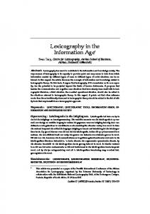
Having these objectives in mind and considering the coworker scenario for SMEs, a robot system (Figure 1) was designed to allow human‐robot interaction both at the programming and task execution stages.
Industrial robot
Force/torque sensor
PC for speech recognition
Headset Figure 1 – Programming‐by‐demonstration system in the laboratory. 2. Test bed: system description The system presented in this section was developed to constitute a test bed for the development and demonstration of programming‐by‐demonstration techniques suitable to be used with SME related projects. It is composed of: a) Personal computer (laptop) which runs the user interface software and the speech recognition software. The user can program the system using its own voice which requires an automatic speech recognition engine (ASR) for command identification, and a Text‐to‐ speech engine (TTS) for providing feedback to the user [1, 6]. The speech features are included in a user interface application that interprets user commands, generates and packs the robot code, and manages the required communication with the robot controller; b) Industrial robot manipulator from ABB Robotics (ABB IRB140) equipped with the IRC5 robot controller [11]. This robot is largely used in industry and fully adapted to SME applications, being representative of the type of solutions aimed in this paper; c) Force‐torque sensor (ATI Industrial Automation, titanium NANO17 model – figure 2) adapted to the wrist of the robot manipulator [12]. The sensor is attached to the robot controller using a PCI analog board, which allows to use the force‐torque sensor with
motion instructions (this requires de ABB force control option installed in the robot controller to effectively use this feature); d) Special tool designed to help the user to guide the robot during motion programming (figures 2 and 3). This aluminum tool was designed to be attached between the sensor and any working tool attached to the robot wrist.
Figure 2 – ATI force‐torque sensor attached to the robot wrist.
Figure 3 – Wrist tool designed to guide the robot controller. As already mentioned, the ABB robot controller has a built‐in force control mechanism that enables users to implement force control to tailor the robot motion using the force‐torque information received from the sensor [13]. Basically, the controller implements an active force controller which can influence the position control to achieve constant force during a planned motion. This feature is only used by the controller if activated by a specific robot instruction, and can be deactivated when not needed anymore: both these actions are offered, byt the PbD system, as remote services to the user (speech commands). The force control feature is part of the “machining FC” option [13] that must be installed on the robot controller. The analog signals coming from the force‐torque sensor are routed through the PCI analog‐to‐digital board to the robot controller and used to control the robot motion when force control is activated (figure 2). 2.1. Robot controller software The ABB IRC5 robot controller is a powerful multitasking computer system which offers several interconnecting possibilities with remote machines, ranging from serial ports and several types of fieldbuses to Ethernet. This allows programmers and system designers to consider several connection strategies. It also provides outstanding robot control capabilities, programming environment and features, along with advanced system and human machine interfaces. To run the PbD system presented in this paper the robot controller runs two very different types of applications: •
The socket server used to implement the remote services and offer them to the remote clients;
•
The application software built to perform certain tasks. This software also enables the user to remotely load and unload new options, and consequently it is also implemented as a server. Task 1 Main module running on task 1 Task 2 TCP/IP socket server running on task 2 Figure 4 ‐ View of the tasks available on the system using RobotStudio Online (ABB)
The above mentioned applications (fully developed for the PbD system) are different in terms of objectives and requirements. Consequently, since the robot control system is a multitasking system, each of them was designed to run in their own task (process) – see Figure 4. One interesting development would be to use an industrial robot programming language to generate services to be later consumed in a service‐oriented industrial manufacturing cell [20]. This would make programming easier and constitute an interesting code‐first approach to specifying services within a SOA environment, contributing to the mandatory compatibility with the existing robot technology. 2.1.1 Communication Server The client‐server software architecture seems to be the best approach to implement the robot‐ computer communication. Consequently, a TCP/IP socket server was developed to run on the robot controller (task 1) and handle the remote calls. The server offers the following generic services: 1. System state services, which enable the remote user to change the controller state and obtain information about the actual state; 2. Variable read/write services to access any type o program and system variables; 3. File access services to read and write files to the robot controller; 4. IO read/write services to read/change digital and analog signals; 5. Module management services to enable the remote user to load/unload program modules, start/stop execution and monitor its operation.
A TCP/IP socket server can work like a switch‐case‐do cycle driven by the received message. The first word of the received message, named “command”, can be used to drive the cycle and discriminate the option to execute, implementing in this way the services it was designed to offer. Consequently, the TCP/IP server (sock_srv, running on task 2) should have a basic structure like the one represented in Figure 5. PROC sock_srv() SocketCreate server_socket; SocketBind server_socket, "172.16.0.89", 2004; SocketListen server_socket; WHILE TRUE DO SocketAccept server_socket, client_socket; SocketReceive client_socket \Str := receive_string; extract_INFO_from_message (command, parameter{i}); TEST command Case “motor_on” motor_on(result); SocketSend client_socket, result; Case “motor_off” motor_off(result); SocketSend client_socket, result; Case “write_num” write_num(parameter1, parameter2, result); SocketSend client_socket, result; Case “read_num” read_num(parameter1, result); SocketSend client_socket, result; … ENDTEST SocketClose client_socket; ENDWHILE ERROR_HANDLER; ENDPROC
Figure 5 ‐ Basic structure of the TCP/IP socket server running on the robot controller The server briefly presented in Figure 5 implements the services defined above. Furthermore, the command strings have a simple structure: command parameter_1 parameter_2 … parameter_N i.e., the command string starts with a word representing the “command” (used by the server to discriminate what is the service the user wants to execute), followed by other words corresponding to the “parameters” associated with the “command”. For example:
Action Motor_ON Motor_OFF
Command String “motor_on” “motor_off”
Read_num “read_num variable_name” Write_num “write_num variable_name value” Program_start “program_start module” Program_stop “program_stop module” … where “variable_name” is the name of the variable to read, “value” is the new value to assign to the variable, and “module” is the name of the module to start or stop. 2.1.2 Application Software As already mentioned the application software is built like a server as a way to increase flexibility, allowing system designers to add new functionalities as needed. The basic idea is simple and not very different from the concept used when implementing any remote server. If the system designer can access robot program variables, then he can design his own services and offer them to the remote clients. A simple switch‐case‐do cycle, driven by a variable controlled from the calling client, would do the job: switch (decision) { case 0: call service_0; break; routine that implements service_0 case 1: call service_1; break; case 2: call service_2; break; … case n: call service_n; break; } Note: “decision” is a numeric variable accessible from the remote computer using the TCP/IP service “write_num”. Consequently, making the call to any service a parameterized call, i.e., a call to a function specified by a string value for example, it is possible to download a module to the system, load it o memory, make service_x = module_name, and execute it just by making decision = x, where x is a number from 0 to n. This means that the system programmer can add, change or upgrade system functionality just by uploading modules to the robot controller making them available to users as new services. 2.2 Computer Software Having presented the robot controller software, it is clear that it constitutes a basic infrastructure to add new functionality to an existent system. The only thing needed is a program module with the necessary code to fulfill the required task. Consequently, the PbD system must generate executable robot code that can be uploaded to the robot controller and be able to command its execution.
There are several ways to this end, but in the implementation presented in this paper the following options were adopted: 1. Speech interface to allow an easy and natural way to command the system. The developed speech interface works both with English and Portuguese and uses ASR and TTS engines provided by the Microsoft Language Development Centre (MDLC ‐ Portugal) as a result of an R&D cooperation. The commands are specified using XML grammars which is considered, among other options, a standard and handy way to specify speech commands; 2. A client application that runs the speech recognition software, converts the spoken commands into robot instructions and aggregate them into robot modules, handle the communication with the robot controller and manage the executable code; 3. Manage directly the robot state, which enable the user to activate/deactivate features on the robot controller and use them for better fulfill the task being pursued. 4. Control directly the robot controller IO signals which enable the user to access the sensors and actuators attached to the robot. 5. Run the software on a .NET platform which is quite representative in industry. The software is also completely developed in C# which makes it quite easy to read and understand. In the following sections the computer application developed for the PbD system presented in this paper will be briefly described just to clarify the design options taken. 2.2.1 Speech Interface Using speech interfaces is a big improvement to human‐machine interface (HMI) systems, because of the following reasons: •
Speech is a natural interface, similar to the “interface” we share with other humans, that is robust enough to be used with demanding applications. That will change drastically the way humans interface with machines
•
Speech makes robot control and supervision possible from simple multi‐robot interfaces. In the presented cases, common PCs were used, along with a normal noise‐suppressing headset microphone
•
Speech reduces the amount and complexity of different HMI interfaces, usually developed for each application. Since a PC platform is used, which carry currently very good computing power, ASR systems become affordable and simple to use.
Speech recognition systems can be separated into several different classes depending on the types of utterances they have the ability to recognize. These classes are based on the fact that one of the difficulties of ASR is the ability to determine when a speaker starts and finishes an utterance. Most packages can fit into more than one class, depending on which mode they're using. Isolated words: Isolated word recognizers usually require each utterance to have quiet (lack of an audio signal) on both sides of the sample window. It doesn't mean that it accepts single words, but does require a single utterance at a time. Often, these systems have "listen/not‐listen" states,
where they require the speaker to wait between utterances (usually doing processing during the pauses). Isolated utterance might be a better name for this class. Connected words: Connected word systems (or more correctly “connected utterances”) are similar to isolated words, but allow separate utterances to be run‐together with a minimal pause between them. Continuous speech: Continuous recognition is the next step. Recognizers with continuous speech capabilities are some of the most difficult to create because they must utilize special methods to determine utterance boundaries. Continuous speech recognizers allow users to speak almost naturally, while the computer determines the content. Basically, it's computer dictation and commanding. Spontaneous speech: There appears to be a variety of definitions for what spontaneous speech actually is. At a basic level, it can be thought of as speech that is natural sounding and not rehearsed. An ASR system with spontaneous speech ability should be able to handle a variety of natural speech features such as words being run together, pauses, "ums" and "ahs", slight stutters, etc. Voice verification/identification: Some ASR systems have the ability to identify specific users. This book doesn't cover verification or security systems, because user validation is done using other means. Speech recognition, or speech‐to‐text, involves capturing and digitizing the sound waves, converting them to basic language units or phonemes, constructing words from phonemes, and contextually analyzing the words to ensure correct spelling for words that sound alike (such as “write” and “right”). Recognizers (also referred to as speech recognition engines) are the software drivers that convert the acoustic signal to a digital signal and deliver recognized speech as text to the application. Most recognizers support continuous speech, meaning the user can speak naturally into a microphone at the speed of most conversations. Isolated or discrete speech recognizers require the user to pause after each word, and are currently being replaced by continuous speech engines. Continuous speech recognition engines currently support two modes of speech recognition: •
Dictation, in which the user enters data by reading directly to the computer
•
Command and control, in which the user initiates actions by speaking commands or asking questions
Dictation mode allows users to dictate memos, letters, and e‐mail messages, as well as to enter data using a speech recognition dictation engine. The possibilities for what can be recognized are limited by the size of the recognizer's "grammar" or dictionary of words. Most recognizers that support dictation mode are speaker‐dependent, meaning that accuracy varies based on the user's speaking patterns and accent. To ensure accurate recognition, the application must create or
access a "speaker profile" that includes a detailed map of the user's speech patterns captured in the matching process during recognition. Command and control mode offers developers the easiest implementation of a speech interface in an existing application. In command and control mode, the grammar (or list of recognized words) can be limited to the list of available commands (a much more finite scope than that of continuous dictation grammars, which must encompass nearly the entire dictionary). This mode provides better accuracy and performance, and reduces the processing overhead required by the application. The limited grammar also enables speaker‐independent processing, eliminating the need for speaker profiles or "training" the recognizer. The command and control mode is the one most adapted for speech commanding of robots. From the several continuous speech ASR technologies available, based on personal computers, the Microsoft Speech Engine was selected because it integrates very well with the operating systems we use for HMI, manufacturing cell control, and supervision (Windows XP/NT/2000). The Microsoft Speech Application Programming Interface (SAPI) was also selected, along with the Microsoft’s Speech SDK (version 5.3), to develop the speech and text‐to‐speech software applications. This API provides a nice collection of methods and data structures that integrate very well in the .NET 2003 framework, providing an interesting developing platform that takes advantage of the computing power available from actual personal computers. Finally, the Microsoft’s SAPI 5.3 works with several ASR engines, which gives some freedom to developers to choose the technology and the speech engine. Grammars define the way the ASR recognizes speech from the user. When a sequence included in the grammar is recognized, the engine originates an event that can be handled by the application to perform the planned actions. The SAPI provides the necessary methods and data structures to extract the relevant information from the generated event, so that proper identification and details are obtained. There are three ways to define grammars: using XML files, using binary configuration files (CFG), or using the grammar builder methods and data structures. XML files are a good way to define grammars if a compiler and converter is available, as in the SDK 5.3. In the examples provided in this chapter, the grammar builder methods were used to programmatically construct and modify the grammar. The strategy used here takes into consideration that there should be several robots in the network, running different applications. In that scenario, the user needs to identify the robot first, before sending the command. The following strategy is used, •
All commands start with the word “robot” or “computer”
•
The words that follow constitute the command and the parameters associated with a specific command
Consequently, the grammar used is composed of a “TopLevelRule” with a predetermined initial state, i.e., the ASR system looks for the pre‐command word “Robot” as a precondition to any
recognizable command string. The above mentioned sequence of words constitutes the second level rules, i.e, they are used by the TopLevelRule and aren’t directly recognizable. A rule is defined for each planned action. As a result, the following represents the defined syntax of commands: robot/computer command parameter_i where “robot” or “computer” is the pre‐command word, number represents the robot number, command is the word representing the command to send to the robot, and parameter_i are i words representing the parameters associated with the command. 2.2.2 User Interface The user interface developed for this application is presented in Figure 6. It is basically an application designed to run the speech recognition software, generate the robot instructions from the identified spoken commands and aggregate them into robot executable modules.
X
Z
\
Y
[
Figure 6 – User interface developed for the programming‐by‐demonstration application. The user interface application includes the following main features which are associated with the functions executed by the interface:
1. A window (X) that represents the robot program, using the selected programming language (RAPID in this case), obtained until the moment. The information is represented immediately after user input and can be changed online using speech commands or user manual commands (using mouse and keyboard). Manual commands are listed in another window (Z), along with access to the parameters associated with each instruction. 2. A window (Z) that allows the user to manually manage program files and adjust the obtained robot instructions. The user can manually add new instructions, edit its parameters, load and save files containing robot code, etc. 3. A window (\) to manually send remote calls to the robot controller. To use this feature the user needs to know the details of each remote call, which is only intended for advance users. 4. A window ([) to visualize the behavior of the speech interface. It lists the recognizer and language being used, along with the identified command and the confidence of the identification. 5. A window (Y) that shows the variables associated with the robot program being built. For example, when the user commands a MOVE instruction the software acquires the position of interest, creates a variable of the correspondent type, saves the data in that variable and associates the variable with the MOVE instruction. The next action is to write this information using a coding syntax understandable by the robot controller (code generation). The speech interface has two different pre‐command words: “computer” and “robot”. The first one is associated with commands related with the interface, i.e., commands used to manipulate the interface, add instructions, manage files, variables, etc. The “robot” pre‐command word is associated with commands that actually make remote calls to the robot controller to load/unload modules, and access any of the remote services offered by the TCP/IP server. It can be argued that the presented interface has too much detail and uses a level of technical detail usually irrelevant for a normal user. In fact that was a design option, since the main objective here is to demonstrate functionality. Nevertheless, a final solution to be used with unskilled users should hide the programming details and just show the necessary information to explain the operations being programmed. For example, a MOVE instruction can be identified by a word (MOVE, for example) followed by some indication about the final position, using an application related name (CONVEYOR, PICK, PALLET, TABLE, etc.), and about the velocity (SLOW, NORMAL or FAST): the result could be something like MOVE [TO] CONVEYER FAST. The commands identified by the speech interface are specified to the system using XML grammars, i.e., the command definition is reconfigurable instead of being hard coded in the application. For example, the following XML rule is used to define a few of the robot available instructions: ..
computer
please
… instruction move joint instruction move line instruction wait time instruction wait condition instruction generic
2.2.3 Generating the Robot Code The user interface catches the speech identification events associated with the rules defined in the XML grammar. Those events can be discriminated based on the event information and the defined grammar, and used to run the code associated with each command. Each event must be identified with a confidence higher than 70%; otherwise it is rejected. After proper identification the rule is verified, and if it exists in the command format the associated action is executed. The user always gets feedback about action execution or any error situation. When a programming command is identified the correspondent robot code is generated using the previously selected parameters (all the parameters have default values and can be changed using speech commands). For example, when the MOVE LINE instruction is identified the following routine is called: case "computer instruction move line": { ans_msg.Text = "Messages: Instruction Move Line, master."; janela.Nodes.Insert(current_node + 1, "lineX", "MoveL FCP" + current_robot_position + “,” + velocity + “,” + current_robot_position_prec + “,” + tool); update_nodes(); update_window(); txt_MsgSend1.Text = "command_str 9905"; tts.speak("Instruction Move Line, master."); } break;
The default motion precision in reaching the programmed point is changed using routines like the one bellow: case "robot position final": { ans_msg.Text = "Messages: Position final, master."; current_robot_position_prec = “fine”; tts.speak("Position final, master."); } break;
Similar routines are used for other parameters like velocity or tool information, for example.
Each instruction has its own routine used to generate the correspondent robot code. Consequently, after finalizing a programming task, a full module, containing the necessary variable data, is generated that can be uploaded to the controller and executed. When the execution is commanded the system starts a confirmation dialog with the user (for safety reasons). 3. Example: Teach‐by‐demonstration In this section a complete programming example will be described step‐by‐step. The robot is equipped with a tool that holds a pencil (Figure 7) so that it can be used to draw figures on a paper. The basic idea of the presented example is to contact the table and draw the word SMEROBOTTM.
Figure 7 – Tool used in this example The user starts the application and activates the speech interface just by loading the selected grammar and activating the speech recognition feature. The first thing to do is start a new program. The command is: User: computer new program Robot: New program, master.
This action generates the basic program structure and the necessary files to hold the programming data.
Then the user needs to start the robot and execute the main application:
User: robot motor on Robot: Motor on, master. User: robot program start Robot: Program start, master. Activating the programming mode puts the system ready for the teach‐by‐demonstration procedure: User: robot mode programming Robot: Programming mode, master. Robot force control feature activated: contact force = 0, damping factors light for easy moving all axis..
User: robot force activate Robot: Force control activated, master.
The robot can now be guided by hand [14] enabling the user to move it to the desired positions: this means that the user can easily reach the positions and orientations more adapted for the task being programmed. After reaching a desired position the user can command a MOVE instruction using the velocity and precision values in use. For example, the following sequence of commands will draw the first “S” of the desired word: User moves the robot to 10mm above the beginning of the character “S”. User: robot position final
defines maximum precision
Robot: Position final, master. User: computer instruction move joint.
acquires position and sets MOVEJ [11]
Robot: Instruction move joint, master. User moves the robot to touch the paper (point 1) and draw the character “S” using straight lines (6 points are necessary). User: computer instruction move line. Robot: Instruction move line, master. User moves the robot to point 2. User: computer instruction move line. Robot: Instruction move line, master. …
acquires position and sets MOVEL [11]
After finalizing the program, the user should save the module, upload it to the robot controller and execute it (figure 8): User: computer save program Robot: Save program, master. User: robot load module Robot: Load module, Master.
Robot is saved using the RAPID language syntax [11] Module uploaded to the robot controller using the services offered by the TCP/IP server
User: robot execute Robot: Are you sure, master? User: robot yes/no Robot: Executing, master/Ok. Command aborted, master.
Figure 8 – Module fcteste6 loaded to the robot controller ready for execution.
Figure 8 shows the modules loaded in the robot control system (the view is obtained from RobotStudio Online, a tool that enables the users to browse the applications loaded in the controller). The fcteste6 module is the one built in the example presented in this section, after being uploaded to the system. Figure 8 shows part of the PbD user interface (right) with the RobotStudio Online window bellow. It is important to stress out that the robot program built in this section was completely obtained without writing a single line of code, but instead just by moving the robot to the desired positions and adding the required robot instructions using speech. Even the upload task of the obtained module to the robot controller is commanded with speech, along with its execution/termination. Consequently, teaching a new feature to the robotic system is accessible to any type of user with only minor training.
Figure 9 – Shell of application developed for SmartPhones 3.1 Using advanced input devices Most of the industrial systems are semiautonomous systems that require only minor operator intervention to operate. Considering a real production setup, it could be interesting to have more portable solutions. Consequently, the use of portable devices like PDAs (Pocket PCs) and mobile phones may be interesting to run part of the monitoring and control software, or even also to run speech interfaces. Part of the features presented in this paper were also developed to run on Pocket PCs and SmartPhones, i.e., on portable devices that run the windows mobile operating
system. Both type of devices are programmable in C# and run equivalent ASR and TTS engines which enables us to develop the same solutions for this portable devices. Figure 9 shows the shell of an application developed to run on SmartPhones (Windows Mobile 5 or higher) to control an industrial system similar to the one presented in this paper. Portable devices may be very interesting for monitoring and on‐the‐task (online) operations, improving in this way the coworker scenario [1‐5]. 5. Conclusion and discussion The programming‐by‐demonstration system presented in this paper proved to be very efficient with the task of programming entirely new features to an industrial robotic system. The system uses a speech interface for user command, and a force controlled guiding system for teaching to the robot the details about the task being programmed. With only a small set of implemented robot instructions it was fairly easy to teach a new task to the robot system, generate the robot code and execute it immediately. Although a particular robot controller was used, the system is in many aspects general, since the options adopted are mainly based on standards. It can obviously be implemented with other robot controllers without significant changes. If fact, most of the features were ported to run with Motoman robots with success [1]. The authors are convinced that this type of PbD systems will constitute a major advantage for SMEs, since most of those companies don’t have the necessary engineering resources to make changes or add new functionalities to their robotic manufacturing systems. Even at the system integrator level these systems are very useful as a way to avoid having specific knowledge about all the controllers they work with: complexity is hidden beyond the speech interfaces and portable interface devices, with specific and user‐friendly APIs making the connection between the programmer and the system. This is the basic idea of high‐level programming framework (HLP) that is really needed to have developers focusing on the problem they have to solve, instead of worrying about the details of getting things setup and done. Future work is directed in supporting these features with specially designed services, supported under a standard service‐oriented architecture (SOA) [15‐18]. This approach will enable users at both operational and integrator levels to reduce their activity to the utilization of services that expose the complete functionality of the system being used, handling all the features and events, allowing them to focus on the task under development or the problem being solved. 6. Acknowledgment This work has been mainly funded by the European Commission’s Sixth Framework Program under grant no. 011838 as part of the Integrated Project SMErobotTM [2]. The authors want also to acknowledge the help of the Portuguese Office of the Microsoft Language Development Centre, specially Professor Miguel Salles Dias, for their support with the Microsoft ASR and TTS engines and related APIs.
7. References [1] Pires, J.N., "Industrial Robots Programming, Building Applications for the Factories of the Future", Springer, New‐York, USA, 2006 [2] SMErobotTM, “The European Robot Initiative for Strengthening the Competitiveness of SMEs in Manufacturing”, IP project, EU FP6, http://www.smerobot.org, 2005‐2009 [3] Pires, J.N., “The Industrial robot as a human coworker: the role of the speech interfaces”, proceedings of the International Conference on Software Development for Enhancing Accessibility and Fighting Info‐exclusion (DSAI 2007), Portugal, November 2007 [4] Pires, J.N., “Robotics for small and medium enterprises: control and programming challenges”, Industrial Robot, Vol. 33, N°6, Emerald, 2006 [5] Dillmann, R., Rogalla O., Ehrenmann M., Zölner R., Bordegoni M., “Learning Robot Behaviour and Skills based on Human Demonstration and Advice: the Machine Learning Paradigm”, proceedings of the 9th International Symposium of Robotics Research (ISRR 1999), pp. 229‐238, Snowbird, Utah, USA, 9‐12 October 1999. [6] Pires, J.N., “Robot‐by‐voice: Experiments on Commanding an Industrial Robot using the Human Voice”, Industrial Robot, an International Journal, Volume 32, Number 6, Emerald Publishing, 2005 [7] Pires, J.N.; Godinho, T.; Araujo, R., “Using Digital Pens to Program Welding Tasks”, Industrial Robot, Emerald: Special Issue on "Robotic Welding", Vol. no.6, 2007 [8] Zhang, J., Von Collani Y., Knoll, A., “Interactive Assembly by a Two‐Arm‐Robot Agent”, Robotics and Autonomous Systems, Vol 29, N.1, pp. 91‐100, 1999 [9] Voyles, R., Khosla, P., “Gesture‐Based Programming: A Preliminary Demonstration”, proceedings of the IEEE International Conference on Robotics and Automation, Detroit, Michinga, pp.708‐713, May, 1999. [10] Hagele, M., Nilsson, K., Pires, JN, chapter on “Industrial robotics” included in the “Handbook of Robotics” – chapter 42, edited by Siciliano, B., and Khatib, O., Springer, 2008 [11] ABB IRB140 Users Manual, ABB Robotics, Vasteras, Sweden, 2007 [12] ATI NANO17 Force‐Torque Sensor, ATI Industrial Automation, http://www.ati‐ia.com/ [13] ABB IRC5 Machining FC Users Manual, ABB Robotics, Vasteras, Sweden, 2007 [14] Pires, J.N., “Videos on Programming‐by‐demonstration”, http://robotics.dem.uc.pt/pbd, 2008 [15] Veiga, G., Pires, J.N., Nilsson, K., “On the use of SOA platforms for industrial robotic cells”, proceedings of Intelligent Manufacturing Systems, IMS2007, Spain, 2007. [16] Veiga, G., Pires, J.N., “PLUG‐AND‐PRODUCE TECHNOLOGIES, On the use of Statecharts for the orchestration of service oriented industrial robotic cells”, proceedings of the ICINCO 2008, International Conference on Informatics Control and Robotics, Madeira, Portugal, May 2008
[17] James, F. and Smith, H., “Service Oriented Paradigms for Industrial Automation”, IEEE Transactions on Industrial Informatics, Vol. 1, no. 1 February 2005. [18] SIRENA Project, Service Infrastructure for Real‐time Networked applications, Eureka Initiative ITEA. www.sirena‐itea.org.sadasd. 2005 [19] Pires, J.N., Godinho, T. Nilsson, K., Haage M., Meyer, C.,” Programming industrial robots using advanced input‐output devices: test‐case example using a CAD package and a digital pen based on the Anoto technology”, International Journal of Online Engineering, Volume 3, Number 3 [20] Veiga, G., Pires, J.N., “Using Robot Programming Languages to Specify Service Contracts”, Proceedings of Controlo‐2008, IFAC/Portuguese Conference on Automatic Control, Vila‐Real, Portugal, July, 2008