duce large continuous streams of data, but programming models provided by ... Programmer work- bench; C.2.4 [Computer-Communication Networks]: Dis- .... Filter node - Take a time series of data with a degree n and produce another time ...
Streamflow -Programming Model for Data Streaming in Scientific Workflows ∗
Chathura Herath and Beth Plale School of Informatics, Indiana University, Bloomington, Indiana. {cherath, plale}@cs.indiana.edu
ABSTRACT Geo-sciences involve large-scale parallel models, high resolution real time data from highly asynchronous and heterogeneous sensor networks and instruments, and complex analysis and visualization tools. Scientific workflows are an accepted approach to executing sequences of tasks on scientists’ behalf during scientific investigation. Many geo-science workflows have the need to interact with sensors that produce large continuous streams of data, but programming models provided by scientific workflows are not equipped to handle continuous data streams. This paper proposes a framework that utilizes scientific workflow infrastructure and the benefits of complex event processing to compensate for the impedance mismatch between scientific workflows and continuous data streams. Further we propose and formalize new workflow semantics that would allow the users to not only incorporate stream in scientific workflow, but also make use of the functionalities provided by the complex event processing systems effective within the scientific workflows.
Categories and Subject Descriptors D.2.6 [ Programming Environments ]: Programmer workbench; C.2.4 [Computer-Communication Networks]: Distributed Systems—Distributed applications; H.4.1 [ Office Automation]: Workflow management
1.
INTRODUCTION
Geo sciences over the years have adopted scientific workflows [28] as a viable means for capturing scientific experiments because of the simple programming abstraction it provides, easy repeatability of experiments and ability to share experiments among peers [25]. Scientific workflows are designed to handle static input data and most scientific experiments have the nature of being reused with different ∗ This work has been funded in part through awards NSF CSR-0720580 and NSF EIA-0202048.
input datasets. The reusability of a given scientific workflow is sometimes influenced by the repeatable nature of the input datasets in the particular scientific domain. The scientific workflow systems in many science gateways [27] like LEAD (Linked Environment for Atmospheric Discovery) [7], ACES (Asia-Pacific Cooperation for Earthquake Simulation) [10], Astroportal [22], etc, primarily deal with the sensor data produced by scientific sensors and workflows are rerun with different data sets produced by sensors. In this paper we present a framework that addresses we identify the need for a scientific experiment to interact with event streams because most scientific sensors like weather radars, telescopes, etc tend to produce events of periodic nature which can be modeled as data streams [4]. Identifying these periodic events as streams has advantages of its own because stream processing and complex event processing systems have matured over the years and the advancements in these fields can be leveraged to enhance the processing of the data events generated by scientific sensors. Further the Streams would allow triggered experiments to be setup in a manner so it is possible to monitor streams for particular events and act as reactive systems that would react to environmental changes that are observed by sensors which would be useful for mining of large event streams. Further extending the scientific workflow model to reactive systems is useful because it preserves the investment by applications in geosciences that use scientific workflow systems. The integration of Streams into the workflow system is addressed using a programming model approach by introducing new workflow semantics that would enable scientific workflow designers to incorporate data streams into the experiment without major changes to the infrastructure. The graphical workflow composition has been very successful as a programming model across geo sciences and has had success among the community as the means for representing scientific experiments [19]. In the framework towards extending a workflow composition programming model to accommodate stream processing, special consideration is given not to alter the existing workflow programming model [26] because most scientist are comfortable with concept of scientific workflows [12]. The contribution of this paper is a model that extends a workflow construction paradigm with support for tasks on time sequenced data which would be referred to as Streamflow from here forth. The model preserves the directed con-
trol flow execution graphs that users are familiar with. We demonstrate experimentally that the operators we introduce produce more efficient overall workflow execution times than an alternate approach that does not introduce the new operators. The remainder of the paper is organized as follows. Section 2 provides a background of a workflow composition tool and identifies the motivating requirements. Section 3 presents the formal model and defines the semantics that we introduced in the framework and notation that adds to the discussion. In Section 4 we present the architecture of the Streamflow framework and describe the systems that are used to realize the programming constructs defined in section 3. Section 5 provides an overview of the programming model and how the constructs can be used in a scientific computing environment and how the different components in the framework would participate to realize the semantics that would be used by the scientific workflow user. Section 6 provides an evaluation of the framework with measurements of the overheads and the gains that may offset the overheads introduced by the system. Section 7 concludes and discusses future work.
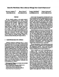
Figure 1: XBaya Graphical workflow composer
different workflow enactment environments have their merits and demerits, and depending on the domain science the optimal workflow enactment environment should be chosen to capitalize on the merits. For the purpose of this paper we focus only on the BPEL execution environment. The work presented in this paper builds upon the functionalities and the programming model presented in scientific workflow systems and provides a programming abstraction for processing data streams.
2.1 Requirements 2.
PROBLEM MOTIVATION
Our research builds upon the conventional workflow systems used in scientific computing and extends it with support for data streams. This decision is not only a natural evolution of scientific workflow, but also we argue that it allows the use of the existing programming model of scientific workflow composition without major changes and alienations of users. A typical workflow system provides a means to compose, orchestrate and monitor workflows and in this framework we use WS-BPEL [10] based generic scientific workflow system developed for the LEAD workflow system [11]. We describe a graphical workflow composition tool XBaya [23] and WSBPEL [10] based workflow execution engine Apache ODE [11] and how these components interact to facilitate a comprehensive workflow system. The interaction between these components and how they fit in a larger workflow system is described in [20]. A workflow composition tool allows a scientist to compose a workflow from existing software and service components without having to be familiar with the workflow languages. Further, workflow composition tools allow for optimizations that can occur when compiling a workflow graph into an executable workflow language [24]. We briefly introduce the XBaya workflow composer which we use as the workflow composition tool for this research. Figure 1 shows the workbench GUI of the XBaya workflow composition and monitoring tool. The programming model proposed in this paper is based on the programming abstractions it offers. XBaya workflow composer provides a high level workflow description language [23] called Abstract DAG model that is independent of conventional workflow execution languages. This independent representation allows the decoupling of workflow composition and workflow execution and allows the internal representation to be transformed to multiple execution languages. XBaya currently supports BPEL 1.1, BPEL 2.0, SCUFL [16], and Python scripts. The
Our goal is to extend the existing support for workflow execution such as is accomplished through XBaya in a way that satisfies the following requirements: • Preserve the workflow programming model for the user. Users are familiar with DAG execution. Stream processing is a different paradigm that when put side by side in an interface to the user during workflow composition it tends to confuse the scientists [13]. In this research we strive to integrate continuous events processing into the familiar DAG model while preserving the familiar DAG control flow. Other research directions have proposed pure workflow approach which has made the programming model somewhat complicated or provide a complete disjoint of workflow and stream processing [16]. • Make the changes transparent to the workflow execution engine so the approach works with an out-ofthe-box engine. Not making changes to the workflow execution model means using existing functionalities provided by workflows as they are and using an external system that reduces the burden on the workflow system in terms of available functionality. This external system we identify as a Complex Event Processing system. • Keep the simple, simple. If users do not need support for streams, the system should act and feel the same as it always has. • Define workflow patterns for use as new workflow semantics that provide a computational model where Complex Event Processing is a first class entity in the workflow.
3. FORMAL MODEL The Streamflow programming model is defined as a programming abstraction that is achieved using patterns that
enable the workflow programmers to program with data streams. Workflows are modeled as Directed Acyclic Graphs (DAG) where the vertices represent the service components and the edges represent dataflow. During the execution of the workflow a given edge delivers a single data token from the source vertex of the Edge to the target vertex. In this paper we discuss programming paradigm that consist of DAG edges with time series of data than single data dependency. A given workflow component may be viewed as a function with or without side effects that is invoked upon receiving the data events from the stream. The workflow takes the input and a global state and produces an output and depending on whether the workflow is side effect free or not it may not or may change the global state, respectively. The static nature of the workflow inputs can be observed in this notation because of the workflow execution begins only when all the inputs are available. Once the workflow starts executing the inputs cannot be changed nor is lazy evaluation [15] of inputs allowed.
of events or a time in units depending on how the stream is bounded or simply unbounded if the Stream in indefinite. To enable the user to incorporate real time, data streams into workflows, XBaya introduces a general workflow abstraction type we call Streamflow node type. The significance of this type is all the nodes that belong to this general category show one of the Streamflow patterns listed below and shown in Figure 2. When these Streamflow patterns are used during a workflow composition, we would refer to the resulting control-flow and data-flow structure as a Streamflow. We make use of a quantifier defined as the stream cardinality to identify the relationship between the number of events that are flowing into the Streamflow node and the number of events that flow out. For example n–m stream cardinality represent that over the lifetime of the workflow the Streamflow nodes take n input events and produce m output events. Figure 2 shows the classification of these different node types based on their stream cardinality.
The edges in the workflow graph are denoted as: Workflow-Edge = ((Service1, outputPort1) −→ (Service2, inputPort1)) where Service1 has outputPort1 which is connected to the inputPort1 of Service 2. This represents a single data event over the lifetime of the workflow passed from Service1 to Service2. The Streamflows supports the Workflow-Edge and also introduces the Stream-Edge denoted by: Stream-Edge= ((Service1, outputPort1) stream (Service2, inputPort1)) −−−−→ where Stream-Edge represent a stream of data that may pass through the edge over the lifetime of the workflow. In other words Service1 would produce a data stream and that stream is channeled to Service2 via the Stream-Edge. For the purpose of completion we would allow Input nodes and Output nodes be connected to services input ports and output ports respectively and as a convention they will be names Input-Nodei or Output-Nodei. These will only be mentioned when necessary and it is assumed the workflows always have Input nodes and Output nodes connected to the remainder of the data ports when not specified. Some services have one output port and one input port in such cases we would adopt the notion where Service1 −→ Service2 represents the edge and when there is no ambiguity we would use this notation in a sequence such as S1 −→ S2 −→ S3. Sometimes the number of events that may be channeled via a different Streamflow edges may vary and where possible we try to quantify the events that may pass through an edge. We define Weight of a Streamflow edge as follows to capture this information. Weight(E) = 1 if Workflow-Edge Weight(E) ≥ 1 if it s a Stream Edge and would be a number
• Active node - Take time series of data as input and output a time series with one to one mapping.(n–n) • Filter node - Take a time series of data with a degree n and produce another time series with a degree m where n>m. (n–m; n>m) Besides the above two patterns we define two more patterns which are distinct node types. • Stream sink - Take a time series of data as a input and produce a single output. (n–1) • Stream generator - Take a single input of data and produce a time series. (1–n) These node types in fact occur at the Streamflow workflow boundaries of the graph where Stream generator nodes turns downstream nodes into Streamflow nodes and the Stream sink nodes have as upstream node as a Streamflow node but has all its downstream nodes as conventional workflow nodes. For example in the following workflow S3 is a Stream Generator, S6 is a Stream sink and S4and S5 are could be either Active nodes or Filter node. S1 −→ S2 −→ S3 stream S4 stream S5 stream S6 −→ S7 −−−−→ −−−−→ −−−−→ −→ S8 According to above definitions the conventional workflows may be viewed as graphs consisting of Streamflow nodes with stream cardinality 1–1. The Active nodes are the only nodes that preserve the weight of the input and the output edge, thus are proper mathematical functions where each inputs corresponding output can be enumerated as a list of pairs. Because of this conventional web service nodes can be used as Active node implementations and in the scope of this discussion the only implementation of active nodes that is discussed is in fact
activity receives an event from the time series and invokes some service with the incoming event as the argument. Filter Node: The filter node, V3 has the effect of reducing the stream frequency by discarding events. A stream of events with 1 second inter-arrival rate and a filter that filters every other event would output a stream with a 2 second inter-arrival rate to a downstream node. Filter Nodes do not exhibit a 1to-1 mapping between input events and output events, that is it exhibits properties of a mathematical partial function being single valued but need not be total.
Figure 2: Streamflow patterns
conventional web service nodes. Implementation of Filter node, Stream sink and Stream generator is only possible within the context of the stream engine because they rely upon the functionality provided by Complex Event Processing [8] (CEP) system which is discussed as below. Active Node: The active node, V2 in the Figure 3, takes a data stream {e1, e2, e6} as input and produces a data stream as output subject to the following rules: • The active node executes over each event in the data stream. • Simplifying assumption: an active node has only 1 stream input and may have one or more static inputs. • The input Stream Edge weight of the active node is same as the output Stream Edge Weight. In other words active node has a 1-to-1 mapping that equates the number of inputs on the time series to the number of outputs. Each input event in the stream of the node has exactly one corresponding output. Or it exhibits the properties of a mathematical function, being single valued and total. In workflow context the function could be defined as a web services. The Active node is implemented through a new BPEL workflow semantic that uses existing workflow semantics shown below. Active node is a defined as a loop activity that contains a receive activity followed by a invoke activity. The receive
In workflow context the partial function behavior is a side effect of publishing all the events in the event stream to a CEP system and running a CEP query against them. Some events in the event stream would satisfy the CEP query and others don’t thus giving the behavior of a filter or a partial function. The filtering logic for filter node needs to be specified using CEP language, EPL [1] (Event Processing Language). An example filtering configuration used in context of a Filter node could look like the following declarative query. It maintains an event window of five events of type RadarDataStream and this event type has a property called reflectivity. Events are selected that have reflectivity higher than 3.2. The query produces a combined data event containing five RadarDataStream events. So the stream cardinality of the Filter node with the following filter declaration is 5n–n. Select * From RadarDataStream(reflectivity>3.2) .win:length_batch(5). Most complex event processing languages provide a means for selection, projection, joins, event windows and event window operators, grouping, reordering, pattern matching and other useful declarative semantics. Stream sink: Stream sink may be viewed at as an extreme case of the filter node where all events except one are filtered. But in reality Stream sinks are more like aggregators of time series and could evaluate an entire time series and produce a single summarizing event. Fact that its out Edge weight is always one makes it possible for it to have downstream nodes that exhibit the conventional workflow node characteristics. A variation of the stream sink produced by publishing the data stream back to the stream engine and this would terminate all the data flow in the Streamflow. Stream generator: Stream generator is a special service call that initiates a time series of data as its output so output of the Stream generator always need to be connected to a Streamflow type node, i.e. active node or a filter node and have the viral effect on the downstream. The sensors that produce data streams would be abstracted using Stream generators.
Figure 3: Streamflow
Figure 4: Streamflow Architecture
The Streamflow framework deals with other intricacies like promoting Edge Weight of a Workflow-Edge to match the edge weight of a Stream-Edge. For example the V2 active node in Figure 3 has two inputs one is a Stream-Edge and the other is a static workflow input. During the execution the Streamflow framework ensures the input set to V2 takes the form of {{e1,d}, {e2,d} ...{e6,d}}thus the Edge Weight the static input may appear to have been replaced by a data stream of repeating elements that would match the data stream of the Stream-Edge. So if data Stream is modeled as time series I1, I2, In , it would produce a sequence of outputs O1, O2, On.
streams and the workflows allow the unnecessary events be filtered out thus workflows will not be run on unnecessary data sets and thus saving compute cycles.
4.
STREAMFLOW FRAMEWORK
Our research facilitates data streams to be programmable with scientific workflows. The static nature of workflow inputs makes it challenging to integrate the data streams directly into the workflows thus we use a complex event processing [13] system to make this integration more flexible. Streamflow framework uses Esper [14] complex event processing system to manage high volumes of data events coming in from the Data streams. The workflow sub system is purely SOA based thus the complex event processing system is wrapped in web services with extra functionality to manage the different streams and this service is referred to as the stream Engine. The Stream Engine is built on the reasoning argued in [21] that data streams have increased value when centralized decision logic can exist, and not just be limited to localized decision logic. It is a global repository for the data streams system wide and all the data streams would be channeled through the Stream Engine which would make it a single stream repository against which all the stream queries could be run against. On the other hand Stream Engine sits in between workflows and data streams and thus allows the flexibility of letting data streams be pre-processed and filtered before they reach the workflows. For example a weather forecasting workflow may be interested in radar data streams in a certain region to do a local weather forecast. But the Stream engine may receive radar events that are specially distributed all across the country. So it is necessary to filter out the radar events that falls out of the interested region and the fact that stream engine sits between the data
Many Scientific sensors produce large continuously generated observations and in some cases much of the data is not very interesting. For example a weather radar produces events occurring regardless of weather condition. But once in a while an event occurs that needs urgent attention and evaluation. For example a tornado may start forming in the atmosphere which requires urgent forecasts to determine the strength and path of the weather system. In such a situation it is necessary to trigger much larger experiments to evaluate the event. The pattern matching and other declarative programming constructs supported by complex event processing systems provide a sufficient programming model to capture such scenarios. A rule based system is another possible way of detecting such trigger scenarios. Besides being used for filtering, the Stream engine provides a means to facilitate data binding of streams to workflows. Assume that there exists a data stream S and there exists a type T that every event in the data stream conforms to. If this data stream needs to be processed using a workflow it is necessary that workflow would process inputs of type T. There is a necessity for this disconnect to be resolved and typed checked during the process of deployment which would be explained in the following section.
5. PROGRAMMING MODEL We took a top down approach to defining the programming model. Our first focus was to identify the best approach to integrate stream processing into workflows without disturbing the existing workflow paradigm. This lead to the formalization of several patterns that are presented in the formal model. The integration of the Streams into the workflow system is addressed as a programming model in workflow composition. The graphical workflow composition has been very successful as a programming model in geo sciences and has had enormous success among the community as the means for representing scientific experiments. In the framework of extending this programming model to accommodate stream
Figure 6: Simple Streamflow
workflow as a normal static input workflow and then add a streaming data source to the workflow. It is necessary to identify the different static inputs to the workflow that need to be streamed and drag and drop those static input to the streaming data source node. This represents that once this workflow is deployed those inputs that are in the streaming data source node would come from the complex event processing system. This simple programming model extension makes it easy for the scientist to adopt because it is very similar to composing conventional scientific workflow. Figure 5: Streamflow Deployment
processing special consideration is given to not alter the existing workflow programming model because most scientist are comfortable with the concept of scientific workflows. From the perspective of the workflow composition, when dealing with live observational data feeds or some such event stream, a researcher continues to use a workflow composer. If the experiment involves a data stream of particular data type, the scientist would focus on setting up the workflow as if this workflow is going to process a single event of the data stream. XBaya builds a mechanism to remove the static workflow inputs and connect a data stream of the same type to be connected to that workflow node. At the time of the execution of the workflow it is necessary to understand that this workflow has different execution semantics because of the stream nature of the inputs and XBaya workflow system manages all that execution complexity transparent to the user. To accomplish this we introduce new workflow semantics to the workflow system in the form of a streaming data source. From the perspective of the experimenter the stream data source is an abstract concept representing a continuous data stream. From an architectural standpoint it represents a service that ingests events posted by the data stream service to a workflow that is waiting for a external event to occur for its execution to continue. This new node type is configured through setting a query, an EPR and a time range. The query represents the events within the data stream that are of interest to the researcher. Since a workflow executes once from beginning to end in a linear fashion, yet the data stream is continuous, the time range defines the period of time for which the data stream should be monitored. Finally the EPR indicates to the event processing service where to send data events matching the given query. Composition: The programming model is to compose the
When the user deploys the stream-enabled workflow, the framework compiles the workflow, generates two workflows as follows: • Control Streamflow that initiates the execution and receipts of messages from a CEP system and dispatch to the child workflow as needed. • Child workflow representing the actual scientific workflow without any streaming in it. This is the same as the static data set workflow. Once these two workflows are deployed the system can exist in a runnable state. The dataflow of a conventional workflow is normally represented by an edge from one workflow node to another and represents a single message or event flowing from data out-port to an data in-port. It is important to note that when a streaming data source is introduced to a workflow the cardinality of the dataflow edge changes and edges connected to stream data sources and all subsequent data dependencies represent data streams instead of a single data event. These changes are reflected in the workflow system using the thick blue edges in the control Streamflow 3 and can be clearly seen in Figure 6. These workflows are then compiled to WS-BPEL [2] scripts and be deployed to the workflow engine used by the framework, Apache ODE [3]. Execution: The execution of the composed and deployed workflow begins by invoking the control Streamflow and as shown in Figure 5 the first activity of the control Streamflow is to contact the complex event processing system to register a query that was specified by the users about the type of events that this workflow is interested in and the duration that the continuous query should be valid. This is shown as step 4 in Figure 5. The workflow then waits for the first message to arrive from the stream engine and when the stream engine finds an event that satisfies the query, it sends a message to the waiting workflow process. Once the workflow receives the message and invokes the child work-
flow that it starts executing. Meanwhile the control Streamflow’s Active node would loops back and waits for another observational event and the process continues.
6.
EVALUATION
Evaluation presented in this section focuses on the overheads, latencies and gains of the Streamflow programming model and the measurements try to quantify them when used for interfacing existing scientific workflows with event streams. All the measurements in this evaluation are micro benchmark based and the services involved in the evaluation was deliberately made not to consume time so the measurements would not be affected by the application execution times which depend on the scientific domain. The server components were run in a 8 CPU machine running Duelcore AMD Opteron processors at 1000MHz, 32 GB memory and a client machine where the workflow composer was run had a configuration of 2 CPUs with Intel Pentium 4 CPU 3.20GHz, 2GB memory.
Figure 7: Deployment overhead
Deployment One of the basic measurements associated with the framework is the deployment cost associated with deploying conventional scientific workflow as a Streamflow as shown in Figure 5, i.e. conventional workflow and a control Streamflow that would handle Streaming. Theoretically the extra cost associated with the Streamflow framework is invariant of the complexity of the scientific workflow. The scientific workflow that is used to measure deployment time is defined as following, which would be referred to as WF1. S1 −→ S2 −→ ... Sn-1 −→ Sn The Services are arranged as a sequential workflow and the number of nodes n in the workflow is taken to be a measurement of workflow complexity. When this workflow is deployed as a Streamflow it would generate a control Streamflow (shown in Figure 5 c) with a Stream Generator SG and an Active node Active-WF1 which would dispatch events to the scientific workflow WF1. Finally the resulting output event stream from the Active node is sent to a Stream-Sink. The control Streamflow would look like what is shown in Figure 6. There will be extra deployment overhead for generating and deploying this Control Streamflow that could be defined as follows. SG stream Active-WF1 −−−−→ Active-WF1 stream Stream-Sink −−−−→ Figure 7 compares the median total cost of deploying the scientific workflow and the control Streamflow (step 2 and 3 in Figure 5) against the median overhead associated with deployment of a control Streamflow (step 2 Figure 5). The total deployment time of the workflow increases linearly as the sequential workflow grows but the overhead associated with the Streamflow remains relatively constant as anticipated. So it can be argued that the linear increase in total deployment time is solely attributed to the growth of complexity in the scientific workflow rather than the Streamflow
Figure 8: Event Latency
framework. It can be concluded that the deployment overhead introduced by the Streamflow workflow generation remains constant at less than one second and invariant of the complexity of the scientific workflow. Latency The control Streamflow that manages the data stream for the scientific workflow acts as an intermediary between the stream engine and the scientific workflow and this introduces some latency to the event stream. In Figure 8, the experiment measures how the event latency from the Stream Engine to the scientific workflow behaves under different event rates. Effectively this is the cumulative time that a given event may spend in the Stream Engine and being transferred to control Streamflow (Figure 5 step 7) and eventually arriving at the scientific workflow (Figure 5 Step 8). This Latency would be later referred to as Active-Node-Latency. Figure 8 shows how the median latency changes with the event rate; the measurements were taken in steady state where the output event rate matches the input event rate thus allowing us to conclude that there is no event buildup in the system that could lead to eventual system crash. Performance In Figure 3 we showed a mixture of Streamflow nodes along with a workflow node. For example V1 is a workflow node that does not do streaming whereas V2 is a Streamflow node. If the same problem was solved using a pure workflow, the way to run the experiment would be to compose a workflow with all the nodes in it and for each incoming event launch that workflow. In such a case the V1 node will be invoked multiple times unnecessarily. But in a Streamflow setup V1 would only be invoked once. If a given Stream-
Figure 9: WF0 -Composite workflow
Figure 10: Optimized workflow and Streamflow
flow has nodes such as V1 the compute cycles saved by the Streamflow would not only offset its overhead but also will be efficient. For the purpose of the remainder of the discussion we assume that there exist a scientific workflow WF0 shown in Figure 9 defined as follows where SVSi and Si are all web services.
one output port and rest of the services to have single input port and single output port. S1 −→ S2 −→ ... Sn-1 −→ Sn
Input-Node1 −→ SVS1
Input-Node1−→ (S1, input-port1 )
Input-Node2 −→ (S1, input-port2 )
Input-Node2 −→ (S1, input-port2)
SVS1 −→ SVS2 −→ ... SVSm-1 −→ SVSm
We define the Streamflow WF2 as shown in Figure 10 where SG is the Stream Generator, Active-WF1 is a Active node dispatching events to WF1, SVSi are again pure web services with single input port and single output port. Notice since S1 had two input ports the WF1 service would have two input ports and thus the Active node Active-WF1 has two input ports.
SVSm −→ (S1, input-port1 ) S1 −→ S2 −→ ... Sn-1 −→ Sn Assume that the Input-Node1 has a static input I1 and the SVSi are side effect free web services. Further assume that the values for Input-Node2 is expected to come from a sensor event thus this entire workflow needs to be launched at every occurrence of the sensor event. Let’s assume that event stream in concern is E1, E2, ... Ek and thus the workflow input event stream would be (I1,E1), (I1,E2), ... (I1,Ek). When this workflow is analyzed it can be observed that computation represented by sub workflow [ SVS1 −→ SVS2 −→ ... SVSm-1 −→ SVSm ] is repeated for every event Ei but always produces the same output because Input-Node1 is static and SVSi services are side effect free. It would make sense to calculate it only once thus saving compute resources. If we define running time for a given workflow W for k events as Tk (W) then the running time for the WF0 could be defined as follows where T(Si) and T(SVSi) are time taken by services Si and SVSi respectively. Tk (WF0) =
m k »X X j=1
i=1
T (SV Si) +
n X i=1
T (Si)
–
It should be noted that this measurement of time removes the inter-arrival time between events from the calculation. This is deliberate because time taken from one event to another is a subjective measurement and further taking that time into consideration will not add value to this part of the discussion. Now we make use of the Streamflow semantics to optimize the above workflow. We do this by breaking down the workflow into two parts, a workflow and a Streamflow as shown in Figure 10. We define scientific workflow WF1 as follows where Si is a web service and we select S1 to have two input ports and
SVS1 −→ SVS2 −→ ... SVSm-1 −→ SVSm SVSm stream (Active-WF1, port2 ) −−−−→ SG stream (Active-WF1, port1 ) −−−−→ Active-WF1 stream Stream-Sink −−−−→ Under this setup the WF2’s service components SVSi s would only be executed once during the entire event stream thus saving computation. But this would introduce extra overhead for setting up SG - Stream generator and as calculated in the earlier performance analysis Streamflow introduces latency for event dispatching, the Active-Node-Latency which would be referred to as ANL. Under the assumptions since WF0 can be functionally replaced by WF1 and WF2, we can use this setup to compare the time taken by the Streamflow approach against the WF0 approach for the same event stream E1, E2, ... Ek. The time taken by the new approach to compute this event stream is as follows. Tk (WF1 + WF2) = T (SG) +
m X
T (SV Si)
i=1
+
k »X n X j=1
i=1
– [T (Si) + AN L]
It should be noted that the
m X
T (SV Si) is independent of
i=1
the event stream now, which is a clear performance gain
stream processing by setting up broker network paths and routing the message streams through. Stream Based Functions was computational model proposed in [14] is a combination of dataflow model [16] and process network model [17]. Although the capability of broker networks to provide a robust computational model is evident, the work doesn’t address a programming model so makes it hard for use with real science applications.
Figure 11: Performance improvement
and it would undoubtedly improve the performance of the Streamflow based solution. But there is a constant time ANL which occurs for every event and finally a constant setup time of T(SG). The critical question would be what is be the minimum number of m required to offset the overhead added by the ANL and the following performance analysis shows that at m=1 the Streamflow solution offsets the initial setup cost T(SG) and ANL just after four events. Figure 11 shows the realization of above experiment with m=1 and n=1 so it gives a lower bound on the system performance. The higher the value of m, the faster the Streamflow would outperform WF0. Higher the value of n, T(SG) cost becomes less significant. As cab be seen initially the Streamflow lags due to T(SG), but as the time series progresses the Streamflow events tend to complete execution quicker than the pure workflow approach. We define time series number as the subscript number of a time series of events defined by E1, E2, E3 ... Ek, where higher the number later in the time the event would occur. In the X-axis we use this time series number to present the notion of time independent of the actual time the event was published. So to make the Streamflow based system work better in such kind of arrangement, the Streamflow programmer only needs to find one service that is independent of the event stream. It should be noted that the services used in this experiment have near 0 second turn around time and the time measured are for the transport and framework overheads. When considering real science applications, the initial setup cost is very negligible taken in context of long running science applications, so the minimum affects of the Streamflow framework highlighted here should matter even to a lesser degree. The above is one aspect of the performance gain achieved using the Streamflow programming model. Further workflows may not be launched for every event that arrives at the Stream Engine because of the selectivity of the EPL query registered at the Stream Engine. For example the EPL query presented in section 3 would filter out all the events with reflectivity less than 3.2, so there will be no cost to the workflow system from the events that do not satisfy the query. Further gains may be achieved by bundling events into one big even which would reduce the event rate downstream, thus saving computations.
7.
RELATED WORK
Filter networks have been used for processing data streams and [9] provides a message brokering approach to handle the
The idea of stream based functions, which uses function without side-effect and a controller that calculates which function may be fired depending on the fulfillment of dependencies, has been used in dynamic dataflows. Ptolemy framework [6] designed as a simulation framework supports the Dynamic Data Flow computational model among others that would enable the extension of the data flow principles used in Digital system processing used for data Streaming. The framework proposed in this paper not only complements dataflow like approaches it also provides a mechanism to allow data mining and pattern matching as part of the programming model and a Stream hub which may be used as a common repository for the workflows to resubmit the data streams that they may produce back to the System. Although the Stream hub may appear to be bottleneck, there are many Complex Event Processing systems that support distribution which can achieve high scalability. [18] identifies the specific demands imposed upon the stream processing by data driven computational sciences such as heterogeneous data formats, asynchronous stream, variance in event sizes, etc and proposes a system to compensate for the domain driven requirements on stream processing systems. The significant difference between this research and ours is the programming model extension we propose to scientific workflows which makes the integration more coherent and convenient. Extension of pure workflow semantics to achieve stream processing is presented in [5]. It presents a workflow semantics that would produce a pipeline effect which can be used for stream processing. We distinguish the work presented in this paper by arguing that data streams require stream processing semantic like pattern matching, aggregation, etc and it would be hard to program this using pure workflow. The emphasis is placed upon the programming model rather than the execution model, and to provide a programming interface that has already been in use scientific workflows. The motivation of our research is to extend the existing programming model of workflows without alienation of the scientific workflow designers.
8. CONCLUSION AND FUTURE WORK In this paper we present a programming model using the existing workflow programming model and show how it can be extended to allow scientists to do stream processing. We believe the balanced approach taken by utilizing complex event processing as well as workflow systems brings the best of both technologies together and provides flexible yet simple programming model for Stream processing. Our evaluations show that even though the framework introduces overhead to the existing workflow system, the overhead is minor compared to the execution time of a workflow and these overheads can be offset by gains offered by the Streamflow programming model. We envision the Streamflow framework
used in many different disciplines and are currently exploring possible application of it in meteorology and astronomy. [12] An important issue when dealing with event streams is event ordering and synchronization based on system generated timestamps or domain dependent timestamps. The temporal event ordering is not addressed in this paper and we plan to work on it as part of the future research. Further handling and compensation of missing event is another interesting and important research direction that needs to be considered in context of the Streamflow framework. Another area that needs further investigation is provenance collection of event streams.
9.
ACKNOWLEDGMENTS
[13]
[14]
[15]
We would like to acknowledge discussions with our colleagues, Dennis Gannon, Jeff Cox, Satoshi Shirasuna, Srinath Perera, Suresh Marru and Thilina Gunarathne. [16]
10. REFERENCES [1] Esper event processing language http://esper.codehaus.org/esper-2.0.0/. [2] T. Andrews, F. Curbera, H. Dholakia, Y. Goland, J. Klein, F. Leymann, K. Liu, D. Roller, D. Smith, S. Thatte, et al. Business process execution language for web services 1.1. IBM Developers Library, 2003. [3] Apache Ode. Available electronically at: http://ode. apache. org. Accessed on, 18, 2009. [4] B. Babcock, S. Babu, M. Datar, R. Motwani, and J. Widom. Models and issues in data stream systems. In Proceedings of the twenty-first ACM SIGMOD-SIGACT-SIGART symposium on Principles of database systems, page 16. ACM, 2002. [5] B. Biornstad. A workflow approach to stream processing, PhD Thesis, Computer Science Department, ETH Zurich. [6] J. Buck, S. Ha, E. Lee, and D. Messerschmitt. Ptolemy: A framework for simulating and prototyping heterogeneous systems. International Journal of Computer Simulation, 4(2):155–182, 1994. [7] K. Droegemeier, V. Chandrasekar, R. Clark, D. Gannon, et al. Linked environments for atmospheric discovery (LEAD): A cyberinfrastructure for mesoscale meteorology research and education. In 20th Conf. on Interactive Information Processing Systems for Meteorology, Oceanography, and Hydrology. Citeseer, 2004. [8] O. Etzion. Complex event processing. In IEEE International Conference on Web Services. Citeseer, 2004. [9] G. Fox, G. Aydin, H. Bulut, H. Gadgil, S. Pallickara, M. Pierce, and W. Wu. Management of real-time streaming data Grid services. Concurrency and Computation: Practice and Experience, 19(7):983–998, 2007. [10] G. Fox, S. Ko, M. Pierce, O. Balsoy, J. Kim, S. Lee, K. Kim, S. Oh, X. Rao, M. Varank, et al. Grid services for earthquake science. Concurrency and Computation: Practice and Experience, 14(6-7):371–393, 2002. [11] D. Gannon, B. Plale, M. Christie, L. Fang, Y. Huang, S. Jensen, G. Kandaswamy, S. Marru, S. Pallickara, S. Shirasuna, et al. Service oriented architectures for
[17] [18]
[19]
[20] [21] [22]
[23] [24]
[25]
[26]
[27]
[28]
science gateways on grid systems. Lecture Notes in Computer Science, 3826:21, 2005. Y. Gil, E. Deelman, M. Ellisman, T. Fahringer, G. Fox, D. Gannon, C. Goble, M. Livny, L. Moreau, and J. Myers. Examining the challenges of scientific workflows. Computer, pages 24–32, 2007. C. Herath, J. Cox, S. Perera, D. Gannon, and B. Plale. Events Processing Programming Models for Reactive e-Science Workflows . B. Kienhuis and E. Deprettere. Modeling stream-based applications using the SBF model of computation. The Journal of VLSI Signal Processing, 34(3):291–300, 2003. J. Launchbury. A natural semantics for lazy evaluation. In Proceedings of the 20th ACM SIGPLAN-SIGACT symposium on Principles of programming languages, pages 144–154. ACM New York, NY, USA, 1993. E. Lee and D. Messerschmitt. Synchronous data flow. Proceedings of the IEEE, 75(9):1235–1245, 1987. E. Lee and T. Parks. Dataflow process networks. Proceedings of the IEEE, 83(5):773–801, 1995. Y. Liu, N. Vijayakumar, and B. Plale. Stream processing in data-driven computational science. In Proceedings of the 7th IEEE/ACM International Conference on Grid Computing, pages 160–167. IEEE Computer Society Washington, DC, USA, 2006. S. Majithia, I. Taylor, M. Shields, and I. Wang. Triana as a graphical web services composition toolkit. In Proc. of UK eScience All Hands Meeting, pages 2–4. S. Perera, S. Marru, and C. Herath. Workflow Infrastructure for Multi-scale Science Gateways. B. Plale. Framework for bringing data streams to the grid. Scientific Programming, 12(4):213–223, 2004. I. Raicu, I. Foster, A. Szalay, and G. Turcu. AstroPortal: A Science Gateway for Large-scale Astronomy Data Analysis. In TeraGrid Conference. Citeseer, 2006. S. Satoshi. . PhD thesis, Department of Computer Science, Indiana University, 2007. G. Singh, C. Kesselman, and E. Deelman. Optimizing grid-based workflow execution. Journal of Grid Computing, 3(3):201–219, 2005. I. Taylor. Workflows for e-Science: Scientific Workflows for Grids. Springer-Verlag New York Inc, 2006. I. Taylor, E. Deelman, D. Gannon, and M. Shields. Workflows for e-Science: Scientific Workflows for Grids. Springer-Verlag New York Inc, 2007. N. Wilkins-Diehr, D. Gannon, G. Klimeck, S. Oster, and S. Pamidighantam. TeraGrid Science Gateways and Their Impact on Science. Computer, 41(11):32–41, 2008. J. Yu and R. Buyya. A taxonomy of scientific workflow systems for grid computing. SIGMOD Officers, Committees, and Awardees, 34(3):44, 2005.