Institute of Computer Design and Fault Tolerance ... programming process the user has the possibility to ... For programming service tasks via demonstration a.
Programming Service Tasks in Household Environments by Human Demonstration M. Ehrenmann, R. Z¨ollner, O. Rogalla and R. Dillmann Universit¨at Karlsruhe (TH) Institute of Computer Design and Fault Tolerance Karlsruhe, D-76128, Germany, P.O. Box 6980 {ehrenman|zoellner|rogalla|dillmann}@ira.uka.de phone: +49(0)721/608-4243, fax: +49(0)721/608-7141 Abstract Robot assistants will only reach a mass consumer market when they are easy to use. This applies especially to the way a user programs it’s robot system. The only approach that enables a non expert robot user to teach a system complex tasks is programming by demonstration. This paper explains the basic concepts for mapping typical human actions performed in a household to a robot system: the recognition of the particular user actions, the task representation and the mapping strategy itself. The execution of a mapped program can then be performed on a real robot. An experiment is presented that was carried out concerning a table laying task and proving the feasibility of this approach.
1
Introduction
Robot assistants are expected to be used in a vast field of application. To meet the costumers requirements, they should be helpful, simple and fast. Regarding household and workshop environments in particular, also the following facts should be kept in mind: • Households and workshops are structured environments, but they differ one from another and keep changing steadily. • Each household is tailored to an individuals needs and taste. So, in each household a different set of facilities, furniture and tools is used. Ready-made programs will not be able to cope with such environments. So, flexibility will surely be the most important requirement for the robot’s design. It
must be able to navigate through a changing environment, to adapt it’s recognition abilities to a particular scenery and to manipulate a wide range of objects. Furthermore, for the user it is extremely important to easily adapt his system to his needs, that means, to teach the system what to do and how to do it. We think that the only approach that satisfies the latter condition is programming by demonstration. Other programming techniques like textual coding or teachin, will certainly not be acceptable for a consumer market. Among household tasks, laying a table may be a good example to start with. It is a complex task consisting of several sub steps that may each be solved subsequently. Several and different objects have to be manipulated that are designed for a humans use and may be difficult to handle for a robot. Besides, from the operational point of view, it is a task that seems to be similar to many other every day workings like loading a dishwasher, shopping and unpacking goods or even tidy one’s room. The following article shows how a robot may be programmed to lay a table based on a human’s demonstration that is performed in a completely natural way. The next section 2 presents related approaches that have been developed by others and earlier works that have been carried out at our institute. Then, the recognition of user’s actions is outlined in section 3. This serves as basis for an abstract task representation which is used to generate a robot program depending on it’s kinematic structure and gripper type. Section 4 presents the mapping strategies to do so. During the programming process the user has the possibility to interact with the system, like outlined in section 5. The experimental results for the table laying task can be found in section 6.
2
State of the Art
Several Programming systems and approaches based on human demonstrations have been proposed during the past years. Many of them address special problems or a special subset of objects only. An overview and classification of the approaches can be found in [4]. Learning of action sequences or operation plans is an abstract problem, which supposes a modeling of cognitive skills. When learning complex action sequences, basic manipulation skills or controlling techniques become nonrelevant. In fact, the aim is to generate an abstract description of the demonstration reflecting the users intention and modelling the problem solution preferably optimally. Likewise, a given problem has to be suitably generalised, for example distinguishing parameters specific for the particular demonstration and parameters specific for the problem concept. Both demands a certain insight in the environment and the users performance. Basis for the mapping of a demonstration to a robot system is the task representation and the task analysis. Often, the analysis of a demonstration takes place observing the changes in the scene undertaken by the user. These changes can be described using relational expressions or contact relations [14, 12, 16]. For generalising of a single demonstration mainly explanation based methods are used [15, 9]. Those allow for an adequate generalisation taken from only one example (One-Shot-Learning). Approaches based on One-shotlearning techniques are the only ones feasible for end users since giving many similar performing examples is an annoying task. A physical demonstration in the real world can be too time-consuming and may not be mandatory. Some researchers rely on virtual or iconic demonstrations [2]. The advantage of performances in a virtual world is that here manipulations can be executed that would not be feasible in the real world because of physical constraints. Furthermore, inaccuracies of sensor based approaches do not have to be taken into account. This way, in existing approaches object poses or trajectories [21, 22, 13] and/or object contexts [16, 11, 19, 10] are generalised in an appropriate way. A physical demonstration however is a lot easier to understand and to cope with for the user. Iconic programming starts at an even more abstract level. Here, a user may fall back on a pool of existing or acquired basic skills. These can be retrieved through specific cues (like icons) and embedded in an action sequence. The result of such a demonstration of operator sequences can then be abstracted, generalised and summarised as new knowledge for the system. An example can
be found in the skill-oriented programming system SKORP [2] that helps putting up macro operators out of actuator or cognitive elementary operators interactively. Besides a derivation of action sequences from a user demonstration direct cooperation with users has been investigated. Here, user and robot reside in a common work cell. The user may direct the robot on the basis of a common vocabulary like speech or gestures [24, 23, 20]. But this allows for rudimentary teaching procedures only. A general approach to programming by demonstration together with the processing phases that have to be realized when setting up such a system is outlined in [6]. A discussion of sensor employment and sensor fusion for the action observation can be found in [17, 25, 7]. Here, basic concepts for the classification of dynamic grasps is presented as well.
3
Recognition of Ongoing Action Sequencies
For programming service tasks via demonstration a vast sensor use has to be made for both watching human moves as well as tracking the environment. Especially for learning manipulative tasks gathering hand motion and its pose is curcial. For learning “Pick & Place” or “Fetch & Carry” operations the tracking of manipulated objects in the household environment is of great importance and will lead to the achievement of the high demands on robustness and flexibility of this programming method.
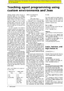
Figure 1: Active Camera Head and Tactile Data Glove For observing a human demonstration the following sensors are used: a data glove, a magnetic field based tracking system for the respective hand and force sensors which are mounted on the finger tips as well as an active trinocular camera head (see figure 1). Object recognition is done by computer vision approaches using fast view-based approaches described in [5]. From
the data glove, the system extracts and smoothes finger joint movements and hand positions in 3D space. To reduce noise in trajectory information, the user’s hand is additionally observed by the camera system. Both measurements are fused using confidence factors, see [7]. This information is stored with discrete time stamps in the world model database. In order to understand the users intention the performed demonstration has to be segmented and analyzed. Therefore in a first step the sensor data has to be preprocessed for extracting reliable measurements and key points, which are used in a second step for segmenting the demonstration.
Grasp Segmentation
Static Grasp
External Force
Dynamic Grasp
Trajectory Segmentation
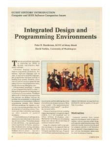
Figure 2: Analyzing segments of a demonstration: force values and finger joint velocity. The segmentation of a recorded demonstration is performed in two steps: 1. Trajectory segmentation This step segments the trajectory of the hand during the manipulation task. Hereby the segmentation is done by detecting grasp actions. Therefore the time of contact between hand and object has to determined. This is done by analyzing the force values with a threshold based algorithm. To improve the reliability of the system the results are fused with a second algorithm, based on the analysis of trajectories of finger poses, velocity and acceleration w.r.t. to minima. Figure 2 shows the trajectories of force values, finger joints and velocity values of three Pick&Place actions. 2. Grasp segmentation For detecting fine manipulation the actions dur-
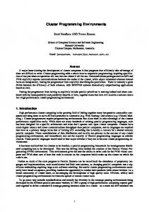
Figure 3: Treelike macro operator knowledge representation
ing a grasp have to be segmented and analyzed. The upper part of figure 2 shows that the shape of the force graph features a relative constant plateau. Due to the fact that no external forces are applied to the object this effect is plausible. But if the grasped object collides with the environment the force profile will change. The results are high peaks i.e. both amplitude and frequency are oscillating, like shown in the lower part of figure 2). Looking to the force values during a grasp, three different profiles can be distinguished: Static Grasp, External Forces and Dynamic Grasps. For more details refer to [25].
The result of the segmentation step is a sequence of elemental actions like moves and static and dynamic grasps. The symbol sequence is now chunked in semantically related groups. These are for example: approach phases, grasp and ungrasp phases. The result is a STRIPS ([8]) like structure of operations ordered in a tree called macro operator. For instance, a macro operator for a simple pickand-place operation has a tree-like structure starting from the whole operation at the root. Figure 3 shows the knowledge representation of pick&place operations of a laying table task. The first branches lead to a symbol for a pick and a place. They are subdivided in approach, grasp/ungrasp and disapproach phases. Finally, the process ends up with the elementary operations at the leaves. Chunking into semantic groups has two advantages. First, conditions for applicability of subparts of the knowledge tree can be tested very easily and second, communication with the user becomes easier for complex task when humans prefer to think in semantic groups rather than in operator sequences.
4
Mapping Tasks on Robot Manipulation Systems
Up to now, problem solving information stored in the macro operators is not directly usable for the target system. Grasps are represented in order to describe human hand configurations and trajectories are not optimal for robot kinematics. Besides, sensor control for the robot like e.g. force control information for the robot system is not extractable from the demonstration, directly. Since we are dealing with pick-andplace operations, we have developed a method for automatically mapping grasps to robot grippers. Furthermore, stored trajectories in the macro become optimized for the execution environment and the target system. The system uses generic robot and gripper models described in [18]. The mapping engine accepts 16 different power and precision grasps of Cutkosky’s grasp hierarchy [3]. As input the symbolic operator description and the positions of the use’s fingers and palm during the grasp are used. We’re calculating an optimal group of coupled fingers; these are fingers having the same grasp direction. These finger groups are asscociated with the chosen gripper type. This helps to orient finger positions for adequate grasp pose. Since the symbolic representation of performed grasps include information about inclosed fingers, only those fingers are used for finding the correct pose. Let’s assume that fingers used for the grasp are numbered as H1 , H2 , . . . , Hn , n ≤ 51 . For coupling fingers with the same grasping direction it is necessary to calculate forces affecting the object. In case of precision grasps the the finger tips are projected on a grasping plane E defined by the finger tip position during the grasp (figure 4). Since the plane might be overdetermined if more than three fingers are used, the plane is determined by using the least square method. Now the force-vectors can be calculated by using the geometric formation of the fingers given by the grasp type and the force value measured by the force sensors on the finger tips. Prismatic and sphere grasps are distuingished. For prismatic grasps all finger forces are assumed to act against the thumb. This leads to a simple calculation of the forces F1 , . . . , Fn , n ≤ 5 according to figure 5. For circular grasps the direction of forces are assumed to act against the finger tip’s center of gravity G. 1 It
should be clear that the number of inclosed fingers can be less than 5
Figure 4: Calculation of a plane E and the gravity point G defined by the finger tip’s positions.
H2
H3
H4
H5
F1 F3
F2
F5
F4
H1
Figure 5: Calculation of forces for a prismatic 5 finger grasp.
H4 H3 H5 H2
G
H1
E)
Figure 6: Calculation of forces for a sphere precision grasp.
To evaluate the coupling of fingers the degree of force coupling is defined: Dc (i, j) =
F~i .F~j |F~i ||F~j |
(1)
This means |Dc (i, j)| ≤ 1 (Dc (i, j) = 0 for f~i ⊥ ~ fj . So the degree of force coupling is high for force acting in the same direction and low for forces acting in orthogonal direction. The degree of force coupling is
used for finding three or two optimal groups of fingers using Arbib’s method [1]. When the optimal group of fingers is found the robot fingers are being assigned to these finger groups. This process is rather easy for a three finger hand, since the three groups of fingers can be assigned directly to the robot fingers. In case there are only two finger groups, two arbitrary robot fingers are selected for being treated as one finger. The grasping position depends on the the grasp type as well as the grasp pose. Since there is no knowledge about the object present, the grasp position must be obtained directly from the performed grasp. For the system, two strategies have been used:
For mapping simple movements of the human demonstration to the robot, we defined a set of logical rules that select sensor constraints depending on the execution context. This is, for example to select a force threshold parallel to the movement when approaching an object or selecting zero-force control during grasping an object. So context information serves for selecting intelligent sensor control. The context information is stored within the macro-operators and is available for processing. Thus, a set of heuristic rules has been defined for handling the system’s behavior depending on the current context. To give an overview the following rules turned out to be useful in specific contexts: • Approach: The main approach direction vector is determined. Force control is set to 0 in orthogonal direction to the approach vector. Along the grasp direction a maximum force threshold is been selected.
• Precition Grasps: The center of gravity G which has been used for calculating the grasp pose serves as reference point for grasping. The robot gripper is positioned relative to this point performing the grasp pose.
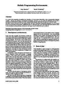
• Grasp: Set force control to 0 in all directions. • Power Grasps: The reference point for power grasping is the user’s palm relative to the object. Thus, the robot’s palm is positioned with a fixed tranformation with respect to this point. Now, the correct grasp pose and position are determined and the system can perform force controlled grasping by closing the fingers. Figure 7 shows 4 different grasp types mapped from human grasp operations to the robot. It can be seen that the robot’s hand position depends strongly on the grasp type.
• Retract: The main approach direction vector is determined. Force control is set to 0 in orthogonal direction to the approach vector. • Transfer: Segments of basic movements are chunked into complex robot moves depending on direction and speed. Summarizing, the mapping module generates a set of default parameters for the target robot system itself as well as for movements and force control. These parameters are directly used for controlling the robot.
5
Human Comments and Advice
Although it is desireable to make hypothesis about the user’s wishes and intention based on only one demonstration, this will not work in the general case. Therefore, we added the possibility to accept and reject interpretations of the human demonstation made by the system. Since the generation of a well working robot program is the ultimate goal of the programming process, the human user can interact with the system in two ways:
Figure 7: Example of different grasp types. 1. 2-finger precision grasp, 2. 3-finger tripoid grasp, 3. circular power grasp, 4. prismatic power grasp
1. Evaluation of hypothesis concerning the human demonstration. E.g. recognized Grasps, grasped objects, important effects in the environment. 2. Evaluation and correction of the robot program that will be generated from the demonstration.
Currently, interaction with the programming system is being established by performing a post processing phase on the demonstration. For this purpose a simulation system has been developed showing the identified objects of the demonstration and actuators (human hand with the respective observed trajectory and robot manipulators) in a 3D environment. During the evaluation phase of the user demonstration all hypothesis about grasps including types and grasped objects are displayed in a replayed scenario. With graphical interfaces the user is prompted for acceptance or rejection of actions. It is also possible to modify the relevance of relation necessary for the macrogeneration phase (see figure 8).
Figure 8: Dialogue mask for accepting and rejecting hypothesis made by the system After the modified user demonstration has been mapped to a robot program the correctness of the program is validated in a simulation phase. Here, modification of the environment an gripper trajectories are displayed within the 3D environment. Again the user can interactively modify trajectories or grasp points from the robot if desired (see figure 9). Modifications are being performed by dragging trajectories or grippers to favored positions.
6
Experimental results
For an experiment with this approach, off-the-shelf cups and plates in different forms and colors were used.
Figure 9: Visualization of modifiable robot trajectories.
The examples have been recorded in our training center (see figure 11 left). Here, the mentioned sensors are integrated into an environment allowing free movements without restrictions. In a single demonstration, crockery is placed for one person (see left column of figure 10). The observed actions may be replayed in simulation (see second column). Here, sensor errors get corrected interactively. The system displays it’s hypotheses on recognized actions and their segments in time. After interpreting and abstracting this information, the resulting macro operator may be mapped to a specific robot. For this purpose, our service robot ALBERT was modeled, set up and used (confer third column in figure 10). The robot is equipped with a stereo camera head and a 7 DOF light-weight arm which was shipped by Amtec, Berlin (see figure 11 right). The arm weighs about 35kg and can lift objects of up to 10kg with fully extended modules. A 6 DOF force/torque sensor supplied by the DLR, Munich interconnects the arm with the three finger Barrett hand. The upper body part is mounted on a mobile platform ODETE which was developed at our institute. ODETE is equipped with supersonic sensors and a planar SICK laserscanner for self-localization and obstacle recognition. With its differential drive, the platform enables the robot to move freely in a workshop or household environment. After testing the mapped trajectory, the generated robot program is transfered to ALBERT and executed in the real world (see fourth column in figure 10).
ACKNOWLEDGMENT This work has been supported by the BMBF project “Morpha”.
Figure 10: Experiment Phases
[11] R. Heise. Programming Robots by Example. Technical report, Department of Computer Science, The university of Calgary, 1992. [12] S. Kang and K. Ikeuchi. Temporal Segmentation of Tasks from Human Hand Motion. Technical Report CMU-CS93-150, Computer Science Department, Carnegie Mellon University, Pittsburgh, PA, April 1993. [13] S. Kang and K. Ikeuchi. Toward Automatic Robot Instruction from Perception: Mapping Human Grasps to Manipulator Grasps. Robotics and Automation, 13(1):81–95, Februar 1997.
Figure 11: Training Center (left) and Service Robot “Albert” (right)
[14] Y. Kuniyoshi, M. Inaba, and H. Inoue. Learning by Watching: Extracting Reusable Task Knowledge from Visual Observation of Human Performance. IEEE Transactions on Robotics and Automation, 10(6):799–822, 1994.
References
[15] T. Mitchell. Explanation-based generalization - a unifying view. Machine Learning, 1:47–80, 1986.
[1] M. A. Arbib, T. Iberall, and D. M Lyons. Coordinated Control Programs for Movements of the Hand, chapter unknown, pages 111–129. Springer Verlag, 1985. [2] C. Archibald and E. Petriu. Computational paradigm for creating and executing sensorbased Robot Skills. 24th International Symposium on Industrial Robots, pages 401– 406, 1993. [3] M. R. Cutkosky. On Grasp Choice, Grasp Models, and the Design of Hands for Manufacturing Tasks. IEEE Transactions on Robotics and Automation, 5(3):269–279, 1989.
[16] H. Onda, H. Hirukawa, F. Tomita, T. Suehiro, and K. Takase. Assembly Motion Teaching System using Position/Force Simulator—Generating Control Program. In 10th IEEE/RSJ International Conference on Intelligent Robots and Systems (IROS), pages 389–396, Grenoble, Frankreich, 7.-11. September 1997. [17] O. Rogalla, M. Ehrenmann, and R. Dillmann. A sensor fusion approach for PbD. In Proc. of the IEEE/RSJ Conference Intelligent Robots and Systems, IROS’98, volume 2, pages 1040–1045, 1998.
[4] R. Dillmann, O. Rogalla, M. Ehrenmann, R. Z¨ ollner, and M. Bordegoni. Learning Robot Behaviour and Skills based on Human Demonstration and Advice: the Machine Learning Paradigm. In 9th International Symposium of Robotics Research (ISRR 1999), pages 229–238, Snowbird, Utah, USA, 9.-12. Oktober 1999.
[18] O. Rogalla, K. Pohl, and R. Dillmann. A general Approach for Modeling Robots. In Proceedings of the IEEE International Conference on Intelligent Robots and Systems (IROS), volume 3, pages 1963–1968, 2000.
[5] M. Ehrenmann, D. Ambela, P. Steinhaus, and R. Dillmann. A Comparison of Four Fast Vision-Based Object Recognition Methods for Programing by Demonstration Applications. In Proceedings of the 2000 International Conference on Robotics and Automation (ICRA), volume 1, pages 1862–1867, San Francisco, Kalifornien, USA, 24.–28. April 2000.
[20] A. Steinhage and T. Bergener. Learning by Doing: A Dynamic Architecture for Generating Adaptive Behavioral Sequences. In Proceedings of the Second International ICSC Symposium on Neural Computation (NC), pages 813–820, 2000.
[6] M. Ehrenmann, O. Rogalla, R. Z¨ ollner, and R. Dillmann. Teaching Service Robots complex Tasks: Programming by Demonstration for Workshop and Household Environments. In Proceedings of the 2001 International Conference on Field and Service Robots (FSR), volume 1, pages 397–402, Helsinki, Finnland, 11.–13. Juni 2001.
[19] A. Segre. Machine Learning of Assembly Plans. Kluwer Academic Publishers, 1989.
[21] T. Takahashi. Time Normalization and Analysis Method in Robot Programming from Human Demonstration Data. In Proceedings of the IEEE International Conference on Robotics and Automation (ICRA), Minneapolis, USA, volume 1, pages 37–42, April 1996. [22] C. Tung and A. Kak. Automatic Learning of Assembly Tasks using a Dataglove System. In Proceedings of the International Conference on Intelligent Robots and Systems (IROS), pages 1–8, 1995.
[7] M. Ehrenmann, R. Z¨ ollner, S. Knoop, and R. Dillmann. Sensor Fusion Approaches for Observation of User Actions in Programming by Demonstration. In Proceedings of the 2001 International Conference on Multi Sensor Fusion and Integration for Intelligent Systems (MFI), volume 1, pages 227–232, Baden-Baden, 19.–22. August 2001.
[23] R. Voyles and P. Khosla. Gesture-Based Programming: A Preliminary Demonstration. In Proceedings of the IEEE International Conference on Robotics and Automation, Detroit, Michigan, pages 708–713, Mai 1999.
[8] R.E. Fikes, P.E. Hart, and N.J. Nilsson. Learning and executing generalized robot plans. Artificial Intelligence, 3(4), 1972.
[24] J. Zhang, Y. von Collani, and A. Knoll. Interactive Assembly by a Two-Arm-Robot Agent. Robotics and Autonomous Systems, 1(29):91–100, 1999.
[9] H. Friedrich. Interaktive Programmierung von Manipulationssequenzen. PhD thesis, Universit¨ at Karlsruhe, 1998.
[25] R. Z¨ ollner, O. Rogalla, J. Z¨ ollner, and R. Dillmann. Dynamic Grasp Recognition within the Framework of Programming by Demonstration. In The 10th IEEE International Workshop on Robot and Human Interactive Communication (Roman), pages 418–423, 18.-21. September 2001.
[10] H. Friedrich, S. M¨ unch, R. Dillmann, S. Bocionek, and M. Sassin. Robot programming by demonstration: Supporting the induction by human interaction. Machine Learning, pages 163–189, May/June 1996.