tained simply by keeping the bitstream prefix corresponding to a desired rate. .... We append to the output bitstream the binary encoding of the number of bits ...
Progressive Wavelet Coding of Images Henrique Malvar May 1999 Technical Report MSR-TR-99-26
Microsoft Research Microsoft Corporation One Microsoft Way Redmond, WA 98052
© 1999 IEEE. Published in the IEEE Data Compression Conference, Salt Lake City, UT, pp. 336–343, March 1999. Personal use of this material is permitted. However, permission to reprint/republish this material for advertising or promotional purposes or for creating new collective works for resale or redistribution to servers or lists, or to reuse any copyrighted component of this work in other works must be obtained from the IEEE.
Malvar
MSR-TR-99-26
PWC Image Coding
Abstract Fast and efficient image compression can be achieved with the progressive wavelet coder (PWC) introduced in this paper. Unlike many previous wavelet coders, PWC does not rely on zerotrees or other ordering schemes based on parent-child wavelet relationships. PWC has a very simple structure, based on two key concepts: (1) data-independent reordering and blocking, and (2) lowcomplexity independent encoding of each block via adaptive Rice coding of bit planes. In that way, PWC allows for progressive image encoding that is scalable both in resolution and bit rate, with a fully embedded bitstream. PWC achieves a rate vs. distortion performance that is comparable to that of the state-of-the-art SPIHT (set partitioning in hierarchical trees) coder, but with a better performance/complexity ratio.
1. Introduction In most applications, image (picture) data is usually transmitted in compressed form. For example, Web pages and digital cameras use compressed image formats, with JPEG (Joint Photographic Experts Group [1]) being the most popular when the image does not need to be reconstructed exactly (lossy compression). In many cases, such as in broadcast transmission with receivers connected via channels with different bandwidths, it is desirable that the transmission be progressive. With progressive transmission, the transmitter can send a subset of the original bitstream for a group of receivers; each subset can be chosen in order to achieve a desired level of resolution and fidelity. In layered transmission systems, the bitstream is decomposed in a small number of subsets (layers), in order of resolution and/or fidelity. Each receiver subscribes to as many layers as its connection bandwidth will allow. A particularly useful form of progressive image coding is the one in which the bitstream is embedded, that is, representations of the image at any rate up to the encoding rate can be obtained simply by keeping the bitstream prefix corresponding to a desired rate. Embedded encoding can be achieved simply by applying the well-known bit-plane encoding technique [2] to the scalar-quantized wavelet coefficients. The most significant bit planes will naturally contain many zeros, and therefore can be compressed without loss via entropy coders such as run-length coders. Although such straightforward bit-plane encoding is not much effective when applied to the original image samples [3], it can lead to reasonable performance (sometimes even better than JPEG) when applied to quantized wavelet coefficients. Bit-plane encoding is more efficient if we reorder the wavelet coefficient data in such a way that coefficients with small absolute values tend to get clustered together. That will translate into longer runs of zeros in the bit planes, which can be encoded at lower bit rates. An efficient algorithm for achieving such clustering is the embedded zerotree wavelet (EZW) coder [4], which is based in a straightforward concept. If a wavelet coefficient at a particular scale (resolution level) and spatial location – a parent coefficient – has magnitude below a certain threshold, then it is likely that coefficients at subsequent scales (higher resolution levels) and at the same spatial locations – the offspring – also have magnitudes below that threshold. In that way, the bits in each
2
Malvar
MSR-TR-99-26
PWC Image Coding
bit plane are mapped to symbols that reflect this parent-child relationship. For example, the zero bits of offspring of a zero parent do not need to be transmitted. A similar technique to EZW, but using a different encoding of the parent-offspring relationship, is used in the set partitioning in hierarchical trees (SPIHT) coder [5]. The SPIHT coder is very efficient in clustering zero-valued coefficients at any particular bit plane; it attains very good compression results even without entropy encoding of the bit-plane symbols. With the addition of arithmetic encoding [6] of the bit-plane symbols, SPIHT is one of the most efficient image compression algorithms reported to date. An alternative approach for embedded bit-plane coding of wavelet coefficients was presented in [7]. Instead of using zerotrees or hierarchical trees to map the bit planes into new symbols, the algorithm in [7] uses a spatio-temporal neighborhood relationship to group the bit planes in four subsequences. Each subsequence is then encoded with an elementary Golomb (EG) coder, which is an effective run-length encoder [8]. The algorithm in [7] performs quite closely to SPIHT with arithmetic coding, but has a lower complexity and can encode all bit lanes through a single pass through the wavelet coefficients. Another approach for bit-plane encoding of ordered wavelet coefficients is presented in [9]. In this paper we introduce the PWC coder, an approach for embedded coding that is also based on reordering of the bit planes, but which is even simpler than the algorithm in [7]. The main differences are twofold: (1) no parent-child relationship of significant wavelet coefficients is used, with reordering based solely on a data-independent scale-space coefficient scan, and (2) explicit blocking of the ordered coefficients, allowing for very simple resolution scalability and resolution-based packetization and layering. The PWC coder is described in Section 2, and its performance is compared to that of SPIHT in Section 3. General conclusions are presented in Section 4.
2. PWC Coding As we mentioned above, the PWC coder is based on adaptive run-length encoding of the bit planes of quantized wavelet transform coefficients. The following steps define the encoding algorithm: 1. Given an image array x(m, n), m = 0, 1, …, M – 1, n = 0, 1, …, N – 1, compute its wavelet transform coefficients X(r, s), r = 0, 1, …, M – 1, s = 0, 1, …, N – 1. 2. Each coefficient X(r, s) is quantized according to q (r , s) = sgn( X (r , s)) X (r , s) T
(1)
where sgn(⋅) is the usual signum function and T is a quantization threshold. This step maps the continuous wavelet coefficients X(r, s) into a sequence of integers q(r, s). This is the only step that introduces information loss. 3. The quantized coefficients are reordered and grouped into blocks according to
2
uk (l ) = q rk + mod(l , M B ), sk + l M B
3
7
(2)
Malvar
MSR-TR-99-26
PWC Image Coding
for l = 0, 1, …, L – 1 and k = 0, 1, …, K – 1, where L = M B N B is the block size, K = MN L is the total number of blocks, and MB and NB are defined by M B = M 2 J and N B = N 2 J . The parameter J controls the size of the rectangular blocks of quantized coefficients that are grouped in uk (l ) , i.e. the block size. For each k, the top left corner indices (rk, sk) are defined according to the scan order described in Section 2.1.
; @
4. The blocks are grouped into macroblocks Ui of fixed size LKB, in the form U i = uk (l ) , with k = i K B , i K B + 1, !, i K B + K B − 1 . For each macroblock, its bit planes are successively quantized according to the adaptive Run-length/Rice (RLR) coder described in Section 2.2. We append to the output bitstream the binary encoding of the number of bits used by the RLR code for Ui followed by the actual RLR output bits. We can use the following steps to decode the PWC bitstream:
1. Decode the RLR-coded bits in macroblocks Ui, for i = 0, 1, …, Imax –1. If Imax < K, we will recover a lower resolution version of the wavelet coefficients. Note that within each macroblock we can decode just the first few bit planes, given the desired reconstruction accuracy. We set to zero all bits in the bit planes of q(r, s) that we choose not to decode. We see that resolution scalability is achieved by choosing Imax < K, whereas fidelity scalability is achieved by decoding only a subset of the bit planes for each macroblock. 2. After recovering the q(r, s), the wavelet coefficients are reconstructed by
%K 0, q ( r , s) = 0 X� (r , s) = &T q (r , s) + 1 2 , q (r , s) > 0 K'T q(r , s) − 1 2 , q(r , s) < 0
(3)
We note that the quantization rule in (2) combined with the reconstruction rule in (3) comprise a uniform quantizer with a dead zone around the origin, which is close to being optimal for minimal-entropy scalar quantization of random variables with Laplacian (double-sided exponential) probability distributions [10].
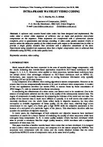
2.1. Reordering of Quantized Wavelet Coefficients To reorder the wavelet coefficients, as described in Step 3 of the PWC encoder, we must define the sequence of top left corner indices (rk, sk). We use the scanning order depicted in Figure 1, J J where M B = M 2 and N B = N 2 control the size of each block. The parameter J should be chosen such that block zero contains precisely all wavelet coefficients at the coarsest resolution, e.g. all scaling function coefficients. Therefore, J must equal to the number of resolution levels
4
Malvar
MSR-TR-99-26
PWC Image Coding
(the tree depth) used in the wavelet transform. It is easy to infer from Figure 1 the sequence of all top left corner indices (rk, sk). It is clear from Figure 1 that in order to decode a complete set of coefficients at any desired level resolution, we need to use all blocks from index 0 up to Kmax –1, where Kmax is a power of four. Therefore, in choosing Imax –1 in Step 1 of the PWC decoder, we should preferable choose Imax – 1 such that Kmax is a power of four. The reason for the alternate scanning of the low-high (LH) and high-low (HL) wavelet coefficients within the same resolution level is simple. Assuming the original image has a particular feature (or no feature) at some spatial location, it is likely that clusters of both the LH and HL subbands, corresponding to that location, will have large (or small) values. Therefore, by ensuring that pairs of blocks from the LH and HL subbands corresponding to the same spatial location appear contiguously in a macroblock, we’re more likely to create clusters of large and small values. That increases the probability of long runs of zeros in the bit planes of the quantized coefficients. Since our clustering technique is data independent, it is likely to be slightly less efficient than the hierarchical trees in SPIHT [5]. The gap in performance is small, though, as shown in Section 3.
2.2. Adaptive Bit-Plane Encoding of Coefficient Blocks In the last step of PWC encoding, each coefficient macroblock should be encoded via bit-plane encoding, in order to produce an embedded bitstream. The number of bit planes is determined by the maximum absolute value of the quantized coefficients within the macroblock. Suppose we start encoding at bit plane v = 0, the most significant bit plane, and proceed with increasing v, towards the least significant bit The algorithm for encoding of each plane is defined by the following steps: 1. Start with a macroblock of coefficients Ui and define the significance flag vector z such that zi = 0 for all i. Set v = 0. 2. Compute bi = v-th bit of |Ui|. 3. Break the set {bi} into two sets: BS = {bi | zi = 0} and BR = {bi | zi = 1}. The set BS corresponds to coefficients whose magnitude have the first significant bit at bit plane v. The set BR corresponds to refinement bits for coefficients whose most significant bit have already been encoded. 4. Encode the sequence of bits in BS by a RLR (run-length/Rice) coder described below, and append the RLR output to the bitstream. 5. Append the sequence of bits in BR to the bitstream. 6. Set zi = 1 for all i such that bi ∈ BS and bi = 1. 7. If the last bit plane has been coded, stop. Otherwise, increase v and return to Step 2.
5
Malvar
MSR-TR-99-26
2NB
NB
0
PWC Image Coding
4NB
8N B
0 1 LH
0
4
8
16
24
32
40
10
18
26
34
42
LH
MB 2 HL
6
3
LH
2 MB 9
12
14
20
28
36
44
7
11
13
15
22
30
38
46
17
25
33
41
19
27
35
43
5
HL 4 MB
HL
"
48-63
21
29
37
45
23
31
39
47
8M B
#
%
Figure 1. Scanning order for defining blocks of wavelet coefficients in PWC. The first block (# 0) contains all coefficients of level 0 of the wavelet tree (coarsest resolution). Blocks 0 to 3 comprise all coefficients of level 1, blocks 0 to 15 comprise all coefficients of level 2, and so forth. Note the alternation of blocks from low-high and high-low subbands at each level.
Note that in Step 5 no entropy encoding of the refinement bits is performed. Since the probability of zeros in BR is very close to 0.5, there is little to gain in entropy encoding. In Step 4, the sequence of bits in BS has long runs of zeros, specially in the initial bit planes (small v). They can be encoded with any efficient encoder for asymmetric binary sources. In PWC we use the runlength/Rice (RLR) encoder [7], [8] defined in Table 1. The RLR coder with parameter k is also known as the elementary Golomb code of order 2 k [7].
6
Malvar
MSR-TR-99-26
Codeword
PWC Image Coding
Input bit sequence
0
Run of 2 k zeros
1c0
Run of c < 2 k zeros followed by a 1, sign Ui = ‘+’ (c is a k-bit number)
1c1
Run of c < 2 k zeros followed by a 1, sign Ui = ‘–’
Table 1. Run-length/Rice (RLR) coder for binary sources with parameter k.
The optimal value of the parameter k depends on the probability that Ui = 0. The higher that probability, the larger we should set k. Before encoding the sequence of Ui ’s in Step 4 above, however, we do not know p0 = Prob{Ui = 0}. We could estimate that probability by counting the number of zeros, and adding a few bits of overhead to specify that count. However, due to the intrinsically nonstationary nature of image data, p0 is likely to change within a macroblock, as we scan through some image feature or flat area. Therefore, in PWC we adapt the parameter k in a backward fashion (i.e., without overhead), increasing it every time we emit a codeword = ‘0’, and decreasing it every time we emit a codeword starting with a ‘1’. We should note that in practice the RLR coder is very close to being an optimal variable-tovariable length coder, since it is the Huffman coder for the Tunstall alphabet extension of the input source [7], [11]. Adaptive arithmetic coding (AC) can be used instead of the adaptive RLR coder described above, but in our tests there was no significant improvement in bit rate by using AC. Therefore, the RLR coder is a better choice, because of its lower complexity.
3. Performance of the PWC Codec We tested the PWC coder against the SPIHT coder [5], using the same wavelet decomposition (the biorthogonal 9/7 filter set), for the grayscale versions of the 512 × 768 images in the Kodak test set [12]. To follow tradition, we have also encoded the grayscale version of the popular 512 × 512 image “Lena” [13]. Table 2 shows the resulting bit rate for a reconstruction peak signal-tonoise ratio PSNR of 40.0 dB [the PSNR is defined as 20 log 10(255/rms_error)], which leads to almost unnoticeable levels of degradation, for all images. In Table 2 SPIHT-B refers to the binary encoded version, and SPIHT-A refers to SPIHT with arithmetic coding. We have also included the rates corresponding to the popular JPEG algorithm (for which we used a flat quantization table, for maximum PSNR performance). From the results in Table 2 we see that the performance of the PWC codec is about the same that of the SPIHT-B codec, which is about 7% worse than that of SPIHT-A (with arithmetic coding) codec, on average. In comparison, the JPEG bit rates are 19% higher than those of the SPIHT-A codec, or 11% higher than those of the PWC codec. In many applications this 7% loss in performance penalty would be a small price to pay, considering the lower computational complexity of PWC compared to SPIHT-A.
7
Malvar
MSR-TR-99-26
Image Lena 1 2 3 4 5 6 7 8 9 10 11 12 13 14 15 16 17 18 19 20 21 22 23 24 Average
JPEG 1.35 2.64 1.27 0.75 1.30 2.50 1.92 0.94 2.80 0.90 1.06 1.75 1.03 3.32 2.26 1.10 1.35 1.25 2.26 1.64 0.93 1.63 1.69 0.56 2.02 1.62
SPIHT - B 1.00 2.60 1.10 0.62 1.09 2.34 1.77 0.80 2.63 0.74 0.87 1.58 0.87 3.23 2.07 0.94 1.17 1.03 2.07 1.47 0.78 1.47 1.54 0.38 1.89 1.46
PWC Image Coding
SPIHT - A 0.93 2.43 0.99 0.57 1.01 2.20 1.66 0.72 2.45 0.68 0.80 1.47 0.79 3.04 1.92 0.86 1.09 0.95 1.93 1.37 0.71 1.37 1.44 0.35 1.77 1.36
PWC 0.98 2.58 1.07 0.63 1.06 2.36 1.76 0.80 2.62 0.77 0.89 1.57 0.87 3.19 2.02 0.94 1.16 1.04 2.04 1.44 0.79 1.46 1.51 0.39 1.89 1.45
Table 2. Bit rates in bits/sample for image encoding algorithms. SPIHT-A uses arithmetic coding, and SPIHT-B uses binary encoding. PWC is the proposed progressive wavelet coder.
We have also compared PWC to SPIHT for many other levels of reconstruction fidelity, with PSNRs varying from 30 dB (usually unacceptably low quality) to 50 dB (visually perfect reconstruction). For all images and all rates, the performance of PWC followed very closely that of SPIHT-B. For high PSNRs, PWC had 2-4% lower bit rates, whereas for low PSNRs PWC had 05% higher bit rates. For example, for the image “Lena,” a PSNR of 50 dB is achieved with rates of 3.21 and 3.12 bits/sample for SPIHT-B and PWC, respectively, and for 33 dB the rates are 0.21 and 0.22 bits/sample, respectively.
8
Malvar
MSR-TR-99-26
PWC Image Coding
4. Conclusion We have introduced a progressive wavelet coder (PWC), which achieves a distortion vs. rate performance in image coding comparable to the state-of-the art SPIHT codec. The main advantage of the PWC codec is it simplicity, since it uses neither data-dependent wavelet coefficient ordering structures such as zerotrees or other spatio-temporal significance relationships, nor complex entropy encoding such as arithmetic coding. Also, PWC can encode the data in separate bitplane-encoded macroblocks, allowing for easy packetization and an embedded bitstream that is scalable both in resolution and in fidelity.
References [1] W. B. Pennebaker and J. L. Mitchell, JPEG Still Image Data Compression Standard. New York: Van Nostrand Reinhold, 1992. [2] J. W. Shwartz and R. C. Baker, “Bit-plane encoding: a technique for source encoding.” IEEE Trans. Aerospace Electron. Syst., vol. 2, pp. 385–392, July 1966. [3] W. K. Pratt, Digital Image Processing. New York: Wiley, 1978, chapter 22. [4] J. Shapiro, “Embedded image coding using zerotrees of wavelet coefficients,” IEEE Trans. Signal Processing, vol. 41, pp. 3445–3462, Dec. 1993. [5] A. Said and W. A. Pearlman, "A new and efficient image codec based on set partitioning in hierarchical trees," IEEE Transactions on Circuits and Systems for Video Tech., vol. 6, pp. 243–250, June 1996. [6] I. H. Witten, R. M. Neal, and J. G. Cleary, “Arithmetic coding for data compression,” Commun. ACM, vol.30, pp.520–540, June1987. [7] E. Ordentlich, M. Weinberger, and G. Seroussi, “A low-complexity modeling approach for embedded coding of wavelet coefficients,” Proc. Data Compression Conference, Snowbird, Utah, Mar. 1998, pp. 408–417. [8] G. G. Langdon, Jr., “An adaptive run-length encoding algorithm,” IBM Tech. Discl. Bull., vol. 26, pp. 3783–3785, Dec. 1983. [9] E Schwartz, A Zandi, and M Boliek. “Implementation of compression with reversible embedded wavelets,” Proc. SPIE 40th Annual Meeting, vol. 2564-04, July1995. [10] G. J. Sullivan, “Efficient scalar quantization of exponential and Laplacian random variables,” IEEE Trans. Inform. Theory, vol. 42, pp. 1365–1374, Sept. 1996. [11] F. Fabris, “Variable-length to variable-length source coding: a greedy step-by-step algorithm,” IEEE Trans. Inform. Theory, vol. 38, pp. 1609–1617, Sept. 1992. [12] The original files for the Kodak PCD set of test images are available in TIFF format at the site ftp://vision.arc.nasa.gov/pub/watson/KodakImages/PCD0992/768x512/. [13] The “Lena” image is available from ftp://ipl.rpi.edu/pub/image/still/usc/gray/.
9