i-ETC: ISEL Academic Journal of Electronics, Telecommunications and Computers CETC2011 Issue, Vol. 2, n. 1 (2013) ID-18
PROJECT WIRELESS SENSOR NETWORK ARCHITECTURE FOR TUNNEL MONITORING 1
Felipe Guimarães Camilo, 1,2Jorge R. Beingolea Garay*, 1Alexandre M. de Oliveira, 1,2Sergio T. Kofuji and 1Fernando Matta 1
Laboratory of Integrated Systems - LSI - Department of Electronic Systems Engineering - LSI - USP 2
Interdisciplinary Center in Interactive Technologies - CITI - USP
Politechnic School, University of São Paulo, CEP 05508-900, São Paulo, SP, Brazil, Phone: +55 11 30919741
{Fguimaraes, Jorge, amanicoba, kofuji, fmatta}@pad.lsi.usp.br
Keywords: Tunnels, Zigbee, Vivaldi, Directional and Omnidirectional Antenna, WSN.
Abstract: This paper presents an architecture for wireless sensor networks (WSN) operating in the 2.4GHz RF band for implementation in environments of small tunnels. The study begins with an objective description of the RF architecture and with the implementation of a RSSI analysis in real scenarios. The designed modules are using directional and omnidirectional antennas for each test scenario. In initial experiment is included a test on the 433MHz band. The developed WSN architecture provides a higher degree of reliability at environments with denser structures (tunnels) and enables the use of directional and omnidirectional antennas for better signal behavior considering the structure of environment to propagation.
1
INTRODUCTION
At present, the need to preserve the environment is vital to our planet. The continual degradation of the environment has triggered terrible environmental disasters converting public places in areas of risk of disaster such as the flooding of towns, overflow in tunnels and others, representing a high risk to city inhabitants. The technology presents itself as an important tool helping at these numerous issues that need to be answered, how to watch extensive forests [1], prevent fires [2], floods [3] landslides and avalanches. One way to prevent these disasters could be based on a continuous monitoring of nature and its phenomena through a wireless sensor networking (WSN) capturing real-time information that would serve to predict or anticipate the outcome of natural phenomena of catastrophic impact [4]. This monitoring provides a simple and instant response to any change in the environment considering parameters such as temperature, acceleration or CO2 concentration, providing objective and constant
information to a diagnostic center [5] enabling on time decision-making to prevent significant damage and loss of human life. However, despite these statements and the numerous advantages of the architectures of RSSF, it is necessary to efficiently determine the type of architecture to be used for each environment to be monitored, considering the power consumption, robustness of the sensors hardware and suitable frequency range to operate in the most diverse and aggressive environments for monitoring [6]. In this respect, the present work aims to present a sensor-nodes architecture followed by a specific study based on received signal strength (RSSI) at 2.4GHz for application in small tunnels considering technical characteristics needed to ensure the quality and reliability of wireless communication at such environment. This paper is organized in the following topics: initially, is presented, the justifications for this work. In Section 2, details are given of RF
*Address correspondence to this author at the Laboratory of Integrated Systems-LSI-Department of Electronic Systems Engineering, Polytechnic School, University of São Paulo, CEP 05508-010, São Paulo, SP, Brazil; Tel: +55 11 30919741; E-mail:
[email protected]
http://journals.isel.pt/index.php/IAJETC
F. Guimarães Camilo et al. | i-ETC - CETC2011 Issue, Vol. 2, n. 1 (2013) ID-18
communication and the various frequency bands. In Section 3, there is an approach to communication in tunnels and its technical fundaments. In section 4, are described the previous steps to the execution of the experiments, such as settings, hardware and test scenarios. Finally in section 5, the conclusions are presented.
2
RF COMMUNICATION
The growth of RF communication and its application in various technological fields have resulted in a rapid saturation of the communication bands, in some cases in an irregular manner, however, it is necessary to argue that even though the free frequencies do not require licenses, the devices used at these frequency bands are ruled by laws and regulations that vary from country to country. The regulations specify aspects of radio such as the allowed spectrum and power for RF systems which falls in the technical specifications of the equipment.
2.1
Overcrowding at the free bands
The exponential growth of electronic devices with wireless communication has resulted in a great diversity of its use and as a consequence the congestion of most bands of free use, grouped as follows: a) Frequency band 433MHz; free Band in Europe and several other countries as a result it presents the problem of band congestion to be considered. This is considered a narrowband [7] and is not designed to have interference resistance to adjacent or coexistent channel. The use of this frequency is subject to a special regulation [8] where the equipment using this frequency must follow certain requirements with the main objective of reducing its congestion.
other free frequency band which has caused the performance, quality and reliability of the transmissions to be questioned. The free use of this frequency eventually ended up demanding the application of some technical specifications to reduce its congestion and its problems of interference, in general, the devices manufactured to operate in this band should meet the regulation [7] considering additional features such as Signal Filtering and Frequency Hopping (FHSS).
2.2
RF Regulation
The operation of the RF communications and electromagnetic compatibility are a new, modern and technical field that has experienced rapid growth in the Brazilian telecommunications scenarios well as internationally possibly as a result of the high complexity of the electronics telecommunication designs in which electromagnetic compatibility (CEM) is present. The standard EN 301 783 corresponds to the European standard while approved in Brazil, which standardizes the use of frequency bands amateur radio bands from 420MHz up to 440MHz and 2.3GHz to 2.4GHz. RF devices used within this band must meet the technical requirements described in this standard [7].
3
COMMUNICATION IN TUNNELS OF SMALL AND LARGE SIZE
The design and choice of RF hardware for specific applications should always follow a meticulous study of the characteristics of the environment as well as of the objectives of the application becoming quite often a difficult task because of fact that the propagation phenomena adopt distinct characteristics in each environment.
b) Frequency band 868MHz; its use is more restricted or the same as the standard norm, as a consequence it has a lower level of interference and or congestion. The 868MHz band is divided into several sub-bands which are strictly reserved for particular functions [9].
This paper considers the architecture for wireless sensor, firmware and analysis of RSSI, a clarification of the technical details a RF communication in tunnels to small or large size.
c) Frequency band 2.4GHz; this band has become quite popular and the requirement is that all devices using it should consider coexistence in its construction; it must have the ability to function in the presence of other devices operating in the same frequency. The 2.4GHz band, due to the features mentioned above, is much more congested than any
The communications in small and large tunnels features peculiar characteristics and behavior. To model the path loss is not a trivial task, being necessary to consider for this work some of the mechanisms that regulate the propagation of radio signal, which can be grouped into three categories: reflection, diffraction and scattering. The first occurs when the electromagnetic wave reaches the surface
i-ETC: ISEL Academic Journal of Electronics, Telecommunications and Computers http://journals.isel.pt/index.php/IAJETC
F. Guimarães Camilo et al. | i-ETC - CETC2011 Issue, Vol. 2, n. 1 (2013) ID-18
of an object with dimensions much larger than the wavelength. The second occurs when there is an object with sharp edges between the transmitter and receiver. And finally the third occurs due to multiple objects of small size between transmitter and receiver. Some of the basic models for "path loss" follow: a) Free Space model: used to predict the propagation of radio signal when the path loss between the transmitter and receiver is free and unobstructed (1).
Being Pr (d) the power of signal received by receiver placed at a d distance from the transmitter, Gt is the gain of the transmitter, Gr is the receiver gain, L is loss factor of the system not related to propagation, and the wavelength in meters. This model illustrates the case where there is only the direct path between the transmitter and receiver, as a result ends up being in most cases, inaccurate. b) Radius Model: It is a more accurate model for which considers the direct and the reflected path in the floor space between the transmitter and receiver [10]. (Fig. 1).
Figure 1: Representation model of 2 rays
In the testing scenario is referenced model (Figure 1) where the received power distribution is given as a function of distance by the following formula (2): ) where ht is the height of the transmitter antenna and hr the height of the receiver antenna. If the distance between the transmitter and the receiver is relatively ), the characteristics of the radio large ( modules are abstracted by the following simplified formula (3):
Where Ct (t for “two-ray”) is a constant and depends on the characteristic of the radio. c) Estimation of losses in indoor environments: Indoors propagation, such as in tunnels, large or small are much more complex than in the open because of an increased number of obstacles which commonly have dimensions that are closer to the length of the propagated signal
wave and at the same time the presence of walls and floors having various features combined to be consider in the complexity of the calculations in each of the propagated test signal. This work considered not only the average loss calculus, but also a description of various attenuation components which combined impact on the propagated waves and on the power level (4).
Where N is the rate of power decay, the frequency in MHz, The value of total losses, distance in meters (d> 1 m), is the loss factor due to ground penetration and is the number of floors between transmitter and receiver. For a zero value of the transmitter and receiver are considered on the same level. And for N = 20, this model is identical to a free space model for outdoor environments. Indoors studies requires N = 18 for a path with losses between transmitter and receiver (an exponent of "path loss" equal to 1.8). Propagation
i-ETC: ISEL Academic Journal of Electronics, Telecommunications and Computers http://journals.isel.pt/index.php/IAJETC
F. Guimarães Camilo et al. | i-ETC - CETC2011 Issue, Vol. 2, n. 1 (2013) ID-18
around corners and walls require N = 40. In the case of long distances, the reflected paths can interfere again and result in N = 40.
3.1. Tunnels of small Dimensions (radius 2.5m). The propagation characteristics described for small tunnels are not different for large tunnels [12] where to determine which type of RF architecture to implement a RSSF is necessary to know the
behavior for each type of frequency within the tunnel.
4
EXPERIMENTS
4.1. Initial Considerations It is increasingly common to need to conduct experiments in real scenarios in order to be able to capture the phenomena and errors that occur in the iteration of the wireless transmitter hardware (RF) and the propagation scenario. In this paper two real scenarios have been used for the experiments yielding great accurace results that can serve as aid in future implementations of wireless communication systems in restricted environments such as small tunnels. a) Hardware RF: The prototypes built for the experiments in real scenarios base on the use of Receiver / Transmitter FM-TRX2-24G modules of Quasar-UK. [13], it contains a CC2500 RF chip from Texas Instruments which is an RF module for low power consumption [14], consistent with other RF transmitters operating on the ZigBee stack using the same frequency band. The baud rate used oscillates between 1.2 and 500 Kbps according to the type of modulation used. The transmitter operates between 2.4 - 2.483 GHz with a sensibility on receptor of up to -104 dBm. (Fig. 2) (Fig. 3). It should be noted that the choice of the Transceiver modules was not solely based on economic factors, but also in technical characteristics which should be considered indoors with very dense structures (reinforced concrete). These specifications should consider the phenomena in signal propagation communication offered by the environment, a relevant feature was to considered the FHSS (Frequency Hopping Spread Spectrum) that not only makes the signal more resistant to interference, but also enables the sharing of bandwidth with many other types of conventional transmitters with minimum interference, which is an essential feature in the 2.4GHz band due to factors of signal sensitivity and high congestion.
i-ETC: ISEL Academic Journal of Electronics, Telecommunications and Computers http://journals.isel.pt/index.php/IAJETC
F. Guimarães Camilo et al. | i-ETC - CETC2011 Issue, Vol. 2, n. 1 (2013) ID-18
Figure 2: Developed prototypes 2.4GHz
In addition in the A scenario (described in section 4.2) a hardware operating at the frequency of 433MHz, the hardware produced by Minteos Company is composed of a radio chip from Texas C1150 [15], and a 8-bit and 2 kb of programmable
Figure 4: Station Base Device - 433Mhz
b) Vivaldi Antenna: This antenna belongs to the family of aperiodic radiators, continuously scaled by an exponential curve. One can say that in theory a Vivaldi antenna has a characteristic semiuniform irradiation over an ultra-wide frequency range [18][19][20][21]. Based on these characteristics, it was decided to choose the Vivaldi antenna, which can be defined as a small planar antenna consisting of a microstrip line transition (Micro Transition Line - MTL) and a radiator in exponential opening (Exponential Line Slot Radiator
Figure 3: Prototypes - Omnidirectional antenna
flash memory microcontroler Atmel ATtiny2313 / V [16]. The base station is composed of processor ATmega 1280v [17] with 4 kb of EEPROM. The radio base station chip is also a C1150 Texas Instruments (Fig 4)(Fig. 5).
Figure 5: Device Sensor 433Mhz
- ESLR) respectively detailed in the following sections: Microstrip transition line: We can define the MTL as a impedance transition line constituted by a separate tape conductor, electrically isolated from a conducting surface (ground plane) by means of a structural substrate as illustrated in Figure 7. This substrate usually has a high dielectric constant (ε> 2) and separates the ground plane from the conductor tape, both consisting of thin- copper-film [21]. (Fig 6).
i-ETC: ISEL Academic Journal of Electronics, Telecommunications and Computers http://journals.isel.pt/index.php/IAJETC
F. Guimarães Camilo et al. | i-ETC - CETC2011 Issue, Vol. 2, n. 1 (2013) ID-18
Figure 6: Microstrip Transition Line where h and t are the substrate and srtip conductor thickness respectively, and w is the strip conductor width [21].
propagation medium (air) in a manner in which is possible to ensure a naturally smooth transition of the signal throughout the RF link. Thus it was considered using a radiator with exponential opening, which is able to ensure an impedance bandwidth relatively large [20][21][22]. Figure 8 illustrates the exponential aperture and its respective function registered in the (x, y) as well as the start and end points of the curve for the design of this opening that forms the proposed electromagnetic radiator.
Figure 8: Detail of the exponential curve of Vivaldi Antenna [DE OLIVEIRA ,2012].
Figure 7: Illustration of the analysis of cross-sectional view of an MTL with detail propagating quasi-TEM [21]
In a structure of the type microstrip line can be seen that the field lines are not contained entirely inside the substrate (Fig. 7), as would happen in a waveguide, so that the mode of propagation on the microstrip line is not purely transverse electromagnetic (TEM), thus defines the propagation as quasi-TEM [21]. According to studies conducted by [21], if the relation between w h is greater than 1, the characteristic impedance (Z0) and the effective dielectric constant (εeff) of a microstrip transmission line can be calculated by:
(5) (6) Irradiation in opening exponential; After performed the calculations and studies to ensure the best impedance matching between the circuit, connectors, cables and MTL, the goal was to design the best radiator between the MTL and the
The curve of opening exponential radiator of the Vivaldi antenna can be obtained according to [20], using an exponential function given by equations (7), 8) and (9), having as its start and end points P1(x1,y1) e P2(x2,y2),
(7) where (8) and (9) c) Firmware: The work and experiment are not limited solely to the development of a prototype for testing, but also the development of an embedded microcontroller firmware for the wireless modules. The firmware in question was developed entirely in C language with a total of 50 pages of code, and can be considered the brain of the modules (prototypes). It should be noted that the flexibility of firmware code allows modifying settings like: Transmission frequency (2.4Ghz - 2.43Ghz), output power (Tx) throughput bit, parameters that must change in each application environment. The code segment responsible for setting up some of the mentioned parameters is shown in figure 9.
i-ETC: ISEL Academic Journal of Electronics, Telecommunications and Computers http://journals.isel.pt/index.php/IAJETC
F. Guimarães Camilo et al. | i-ETC - CETC2011 Issue, Vol. 2, n. 1 (2013) ID-18
Figure 9: Firmware code segment for setting communication parameters.
4.2. Configurations The experimental network (Figure 10) consists of two RF modules (transmitter / receiver) with the characteristics described above, and a programmable gateway with a sensitivity of -101 dBm, transmission rate of up to 250 kbps connected to a base station (Used for collecting and filtering data).
characteristics of high performance, low power consumption, advanced RISC architecture, programmable EPROM 128 \ 256 \ 512 Bytes, among other technical features that maximize the performance of the prototypes developed for this work. Additionally is used a module AVR AVRRISP kII [24] for programming the microcontrollers ATTINY26.
4.3. Scenario of Experiments and Results
Figure 10: Distribution of modules in scenario B - Vivaldi Antennas
In each of the network modules (transmitter Gateway) is used a micro-controller unit to command the RF module embedded. The microcontroller used is ATTINY26 [23] which has
The scenario - A, corresponds to an area of approximately 100m2 belonging to the company Minteos-Italy in a narrow corridor to simulate the conditions of a tunnel, the performed tests corresponds to RSSI values for modules over 2.4Ghz in conditions with obstacles. The distance between the transmitter and receiver module is 15m, for this test is included an antenna RUBBR DUCK (omnidirectional) [25] coupled to the transmitter and at the receiver an antenna PCB 2.4 Ghz. The test was carried out to check the efficacy of the antenna coupled to the circuit (the nominal gain was equal to the actual gain), the measures being made with all the same parameters, just adding to the antenna to the circuit (Fig. 11).
i-ETC: ISEL Academic Journal of Electronics, Telecommunications and Computers http://journals.isel.pt/index.php/IAJETC
F. Guimarães Camilo et al. | i-ETC - CETC2011 Issue, Vol. 2, n. 1 (2013) ID-18
concentrator (gateway) and with a distance of 1m from the ground. For this test was used the Antipodal Vivaldi UWB antenna (Fig.13) developed by the group PAD in the Laboratory of Integrated Systems of the Polytechnic School - USP.
Figure 11: Graphic - RSSI signal with antenna and without antenna. 2.4GHz
Figure 13: Geometry proposed of antipodal Vivaldi antenna – Frequency 2.4Ghz
In figure 13, = Width of opening, = Width of the irradiation plan, = Width of the transmission line or microstri, = Length of Transmission microstrip and = Major axis of the ellipse.
Figure 12: Graphic - RSSI signal, Frequency of 433MHz.
The test verified the proper functioning of the circuit and coupling of the antenna, since the real gain is equal to the nominal. It is also proved that the RSSI signal power at 2.4GHz (Figure 11) was greater than the transmission at 433MHz (Fig. 12) under the same conditions. This result proves the premise of this study, in which the transmission made at higher frequencies have better efficiency when the mediums of transmission are small tunnels or places with the same geometrical conditions.
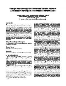
Figure 14: Graphic - RSSI signal with directional Vivaldi antennas and without obstacles
The scenario – B, corresponds to an area of 100m2, comprising one of the corridors of the building of the electrical engineering department from the Polytechnic School of the University of São Paulo Brazil, the modules are distributed randomly with a separation distance of 10m between the modules and
i-ETC: ISEL Academic Journal of Electronics, Telecommunications and Computers http://journals.isel.pt/index.php/IAJETC
F. Guimarães Camilo et al. | i-ETC - CETC2011 Issue, Vol. 2, n. 1 (2013) ID-18
namely: simple geometry (a plate of composite insulator with the faces covered with conductive film), low weight, high bandwidth, high efficiency, small size and high gain [20][26] and showed favorable results in scenarios with and without obstacles, leaving open the possibility to tailor-off the Firmware developed to ZigBee modules for this type of directional antennas.
REFERENCES
Figure 15: Graphic - RSSI signal with directional Vivaldi antennas and with obstacles
The results of the tests (Figures 14 and 15) verifies a considerable variation of the received power when obstructions are introduced between the receiver and transmitter. At the same time it was demonstrated the possibility of hardware circuit to be optimized so that the losses are reduced, higher gains and a longer range to be obtained being able to reach a power of110dB at a distance of approximately 80m.
5.
CONCLUSIONS
This article began with a study on characteristics of the transmission utilizing frequency bands free for use in Europe: 433MH and 2.4GHz. The study aimed to identify the frequency to bring better results in transmissions in small tunnels to develop a product with the best results. After studies and initial tests it was decided for the frequency of 2.4GHz, which was more appropriate for this medium in a way in which it behaves as a waveguide within the structure of the test scenarios. After selecting module the firmware was developed. The experiments indicated successful transmission at 2.4 GHz, and the at the tests within the company Minteos-Italy, a higher power received in the case of 433MHz, confirming the initial hypothesis of the study. 2.4 Ghz tests proved very effective considering the RSSI value obtained for scenarios that use omnidirectional antenna (DUCK RUBBR) and directional (Vivaldi) for the second type of antenna as there is great need for communication over-sight throughout the longitudinal path of the tunnel, the Vivaldi antenna was chosen, since it has the favorable characteristics for the link-sight application applied at communications in tunnels,
o aro y or t , G.; , "Case study of a simple, low power WSN implementation for forest monitoring," Electronics Conference (BEC), 2010 12th Biennial Baltic , vol., no., pp.161-164, 4-6 Oct. 2010. [2] Takeuchi, S.; Yamada, S.; , "Monitoring of forest fire damage by using JERS-1 InSAR," Geoscience and Remote Sensing Symposium, 2002. IGARSS '02. 2002 IEEE International , vol.6, no., pp. 3290- 3292 vol.6, 2002. [3] Jong-uk Lee; Jae-Eon Kim; Daeyoung Kim; Poh Kit Chong; Jungsik Kim; Philjae Jang; , "RFMS: Real-time Flood Monitoring System with wireless sensor networks," Mobile Ad Hoc and Sensor Systems, 2008. MASS 2008. 5th IEEE International Conference on , vol., no., pp.527-528, Sept. 29 2008-Oct. 2 2008. [4] di Tada, N.; Large, T.; , "Information system to assist survivors of disasters," Digital Ecosystems and Technologies (DEST), 2010 4th IEEE International Conference on , vol., no., pp.354-359, 13-16 April 2010 [5] Schmiing, M.; Afonso, P.; Tempera, F.; Santos, R.; , "Integrating recent and future marine technology in the design of Marine Protected Areas the Azores as case study," OCEANS 2009 EUROPE , vol., no., pp.1-7, 11-14 May 2009 [6] Garay, Jorge R.B and S. Kofuji, S. “An Evaluation of The Networks Topologies Star and mesh of The Zigbee Standard: Analysis in Real n ironment ” In: 5º CONTECSI - International Conference on Information Systems and Technology Management, São Paulo, p. 1932-1934, 2008. [7] Frequency standards 420MHz ate 440MHz e 2.4GHz. Available in: http://www.ancom.org ro Access in 15 de January 2011. [8] Norma FREQUENCY ALLOCATIONS RANGE 9 kHz TO 275 GHz. Available in: http://www.itu.int/ITU-D/study_groups/SGP_20022006/JGRES09/CEPT2.pdf. Access in: 15 of January 2011.
i-ETC: ISEL Academic Journal of Electronics, Telecommunications and Computers http://journals.isel.pt/index.php/IAJETC
[9] Frequency standards 800MHz. Available in: http://www.rfm.com/company/etsi.pdf. Access in 10 of January 2011. 0 Paolo Santi “Topology ontrol in wirele ad o and en or network ” AC Comput Sur V 37. pp 164-194. 2005. [11] Kjeldsen, E.; Hopkins, M.; , "An Experimental Look at Rf Propagation in Narrow Tunnels," Military Communications Conference, 2006. MILCOM 2006. IEEE , vol., no., pp.1-7, 23-25 Oct. 2006. [12] Y. Wu, M. Lin, I.J. Wassell, "Modified 2D Finite-Difference Time-Domain Technique for Tunnel Path Loss Prediction," 2nd International Conference on Wireless Communication in Underground and Confined Areas, Val-d’or Canada., Aug 2008. [13] Devices RF. Datasheet. Available in: http://www.quasaruk.co.uk/acatalog/FM_Transceive r_Module.html [14] Rádio CC2500 – Texas Instrument. Datasheet. Available in: http://focus.ti.com/lit/ds/symlink/cc2500.pdf [15] Rádio CC1150 da Texas Instrument. Datasheet Available in: http://focus.ti.com/lit/ds/swrs037a/swrs037a.pdf. Acessado em 15 de Janeiro de 2011. [16] Atmel Microcontrolador ATtiny 2313/v. Datasheet Available in: http://www.atmel.com/dyn/resources/prod_documen ts/doc2543.PDF. Access in 15 de January of 2011. [17] ATMEGA 1280v. Datasheet Available in: vhttp://www.atmel.com/dyn/resources/prod_docume nts/doc2549.PDF. Access in 15 de January of 2011. [18] GREENBERG, M. C.; VIRGA, L.; HAMMOND, C. L. Performance characteristics of
the dual exponentially tapered slot antenna for wireless communication application, IEEE Trans. On Vehicular Technology, v. 52, p.305-310, 2003. [19] MEHDIPOUR, K.; AGHDAM, M.; DANA, R. F. Complete Dispersion Analysis of Vivaldi Antenna For Ultra Wideband Applications. Progress In Electromagnetics Research, PIER, v. 77, p.85-96, 2007. [20] YANG, Y.; WANG, Y.; FATHY, A. E. Design Of Compact Vivaldi Antenna Arrays For UWB See Through Wall Applications. Progress in Electromagnetics Research, PIER n. 82, p.401-418, 2008. [21] De Oliveira, A. M. Sistema transmissor CMOS de Radar UWB por varredura eletrônica com arranjo de antenas Vivaldi. 2012. 170 f. Dissertation (M.Sc.) – Universidade de São Paulo, São Paulo, 2012. [22] GAZIT, E. Improved design of the Vivaldi antenna. IEE Proceedings, v. 135, n. 2, p. 89-92. 1988. [23] Microcontroller ATtiny26. Atmel. Datasheet. Available in: http://www.atmel.com/dyn/resources/prod_documen ts/doc1477.pdf [24] AVR AVRRISP kII. Atmel. Datasheet. Available in: http://www.atmel.com/dyn/resources/prod_documen ts/doc8015.pdf [25] Antenna RUBBR DUCK 2.4Ghz. Datasheet Available in: http://www.globalspec.com/datasheets/2762/LCom/ 705F5DB6-AA59-43F9-A8FE-26B847FB5176 [26] SHIN, J.; SCHAUBERT, D. H. A Parameter Study of Stripline-Fed Vivaldi Notch-Antenna Arrays, IEEE Trans. On Antennas and Propagation, v. 47, n. 5, 1999.