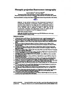
Projection and backprojection in tomography: design choices and considerations Joost Batenburg1,2 , Willem Jan Palenstijn2 , and Jan Sijbers2 1
Centrum Wiskunde & Informatica, Amsterdam, The Netherlands
[email protected] 2
University of Antwerp, Belgium {willemjan.palenstijn,jan.sijbers}@ua.ac.be Abstract Tomography deals with the reconstruction of images from their projections. The projection and backprojection operators are key building blocks of a wide range of tomography algorithms. Although various aspects of these operators have been studied throughout the literature, a review of modeling and implementation aspects is currently lacking. In this work we give an overview of the various design choices to be made when implementing these operations, and their relation to accuracy, computing time and memory requirements. Keywords Tomography; Projection.
1
Introduction
Tomography is a powerful technique for noninvasive three-dimensional (3D) imaging [1]. To create a 3D image of an object, projections are acquired from a range of angles while rotating around the object. From this series of 2D projection images, a 3D reconstruction is computed by a tomographic reconstruction algorithm.
(a)
(b)
Figure 1: (a) Schematic view of a discrete image representation and formation of a single projection: pixel values along sets of lines are accumulated at discrete detector positions; (b) Schematic view of the backprojection operation, accumulating values from projected lines along the various angles in each separate pixel. Depending on the particular application, projections are usually formed by transmitting some form of beam (e.g., X-rays, electrons) through the unknown object and measuring the attenuated beam as it leaves the object. The shape of the beam gives rise to various geometries, such as parallel beam, fan beam (2D front of rays emerging from a single point source) and cone beam (3D cone of rays emerging from a single point). A wide range of reconstruction algorithms have been proposed in the tomography literature. Filtered backprojection (FBP), or the related Feldkamp algorithm for cone-beam reconstruction, are commonly used in practice. Iterative reconstruction methods, such as the Algebraic Reconstruction Technique (ART), Simultaneous Iterative Reconstruction Technique (SIRT), and Ordered Subset Expectation Maximization (OSEM), are more computationally demanding, but can yield more accurate reconstructions in some cases. 1
To deal with the reconstruction problem algorithmically, the image volume is often discretized. Similarly, projections are acquired by a detector that is composed of discrete detector elements. Although practical tomography problems typically deal with 2D projection images of 3D objects, we restrict the illustrations in this paper to 1D projections of a 2D object, for the sake of clarity. Similarly, we will use the term pixel to denote a discrete image element, whereas one would use the term voxel to describe the analogous 3D concept. Fig. 1(a) shows a schematic view of the resulting projection model. After discretization, the problem of tomographic reconstruction can be modeled as a system of linear equations W x = p,
(1)
where W = (wij ) is an m×n matrix such that the value wij represents the contribution of the image pixel j (1 ≤ j ≤ n) to the detector value i (1 ≤ i ≤ m), and the vector p represents the measured projection data. Many reconstruction algorithms can be expressed in terms of one or two of the following building blocks: • Matrix-vector multiplication of the form y = W x, known as the forward projection of x (or simply projection). • Matrix-vector multiplication of the form z = W T p, known as the backprojection of p. Here, W T denotes the transpose of W . The forward projection operation simulates the projections for a given image x; see Fig. 1(a). The backprojection operation distributes a set of projections among the projected lines, accumulating in each pixel the contributions of all lines passing through that pixel; see Fig. 1(b). Typically, some form of scaling or additional processing has to be performed within these operations that depends on the specific algorithm, but their basic structure has strong similarities between the various algorithms. When implementing the forward and backprojection operations, various choices have to be made with respect to accuracy, computing time and memory requirements. Although various aspects of these operators have been studied throughout the literature, a review of modeling and implementation aspects is currently lacking. In this paper we provide an overview of these design choices and discuss their respective advantages and drawbacks.
2
Projection models
The first choice that has to be made when implementing the projection operation is the model that will be used to determine the value of the coefficients wij . Fig. 2 illustrates various models that can be used (see also [4]). In the early days of CT, when computer resources were still highly limited, a 0 − 1 model was often used (Fig. 2(a)), where wij is either 0 or 1, depending on whether line i passes through pixel j or not. Apart from the crude approximation made by binarizing the coefficients, this approach has the disadvantage that lines of equal length can have wildly varying coefficient sums, requiring a form of rescaling. A more accurate model, which is commonly used in practice, is to let wij be the length of intersection between line i and pixel j. In this way, lines of equal length all have the same total weight. Figs. 3(a-c) illustrate the dependency of wij on the position of the detector for a projection along the 0◦ , 30◦ , and 45◦ angles respectively. We call this graph the weight function. For the case where the projection is aligned with the horizontal and vertical axis, illustrated in Fig. 3(a), the weight function has two discontinuities. Due to floating point errors, these can easily lead to pixel weights set to 0, where in fact they should be set to 1, or vice versa. The weighting scheme introduced by Joseph [2] does not have this drawback. Here, the weights wij are the interpolation coefficients obtained when tracing the line row by row (or column by column, depending on the projection angle), and applying linear interpolation between the centers of the two adjacent pixels, as shown in Fig. 2(c). Fig. 3(d) shows the corresponding weight function. An important feature of the matrix W is that it should represent the physical reality linking the projections to the unknown object as well as possible. In practice, projections are not measured 2
along lines, but rather along 2D strips of rays that hit a detector having a certain width. Therefore, the strip model shown in Fig. 2(d), where the weight of a pixel is determined by the intersection area between a strip and a pixel is typically more accurate. Fig. 3(e) shows the corresponding weight function. Alternative approaches for determining weights wij are bilinear interpolation along equidistant points of each projected line (Fig. 2(e)) and numerical integration of radially symmetric basis functions [3] (also known as blobs, Fig. 2(f)).
(a)
(b)
(c)
(d)
(e)
(f)
Figure 2: Various models for computing the projection: (a) Simple 0 − 1 model; (b) Line length; (c) Joseph’s method; (d) Strip area; (e) Interpolation at equidistant points; (f) Integrating radially symmetric basis functions (blobs).
0.0
−1 0 1 detector position
(a)
0.0
−1 0 1 detector position
(b)
0.5
0.0
−1 0 1 detector position
1.0 weight
0.5
1.0 weight
0.5
1.0 weight
1.0 weight
weight
1.0
0.5
0.0
(c)
−1 0 1 detector position
(d)
0.5
0.0
−1 0 1 detector position
(e)
Figure 3: Weight functions that describe the weight of a certain pixel as a function of detector position: (a) Line length model at 0◦ ; (b) Line length model at 30◦ ; (c) Line length model at 45◦ ; (d) Joseph’s method at 30◦ ; (e) Strip area model at 30◦ .
3
Computing the projection
Once the projection model has been chosen, there are still several implementation choices to be made with respect to memory usage and order of computation, which will be discussed in this section.
3.1
Pre-computing vs. on-the-fly computing
The projection matrix W can either be stored explicitly, or its coefficients can be computed onthe-fly when evaluating the forward and backprojection. As each line intersects with only a small fraction of all pixels, the projection matrix is very sparse. Even when storing the matrix in a sparse format, the number of nonzeroes when an n×n×n volume is projected in d directions onto an n×n detector is proportional to n3 d, which means that for large experimental volumes the projection matrix cannot be kept in system memory. For some projection geometries, such as the parallel projection geometry that rotates around a single axis, projection and backprojection can be decomposed into a series of operations on two-dimensional images, greatly reducing the memory footprint. As a general trend in computing, one can say that memory access is gradually becoming slower when compared to actual computation, thereby making it attractive to compute entries of W on-the-fly.
3.2
Pixel-driven vs. ray-driven computing order
Depending on the projection model, the projection and backprojection operations can be implemented based on either a pixel-driven approach, a ray-driven approach, or a combination of both. A pixel-driven implementation essentially iterates over the columns of the projection matrix W , each time computing the projection or backprojection for a single pixel. A ray-driven implementation iterates over the rows of the projection matrix, performing the computation for all pixels on a single projected ray. Both approaches have their own advantages: 3
• A pixel-driven implementation can be used efficiently for Region-of-Interest (ROI) tomography, where only part of the pixels require processing. A pixel-driven backprojection operation is suitable for parallelization, as all write operations access distinct memory addresses (one for each pixel), thereby avoiding write collisions. • A ray-driven implementation is the approach of choice when using one of the interpolation models shown in Fig. 2e-f that depend on traversal of rays. It can provide high efficiency in cases where parts of the projection data must be excluded from the reconstruction, e.g., when the object contains dense materials that absorb all X-rays. Similar to the pixel-driven backprojection operation, a ray-driven projection operation is suitable for parallelization, as all write operations act on distinct memory locations (one for each detector element).
3.3
Weight computation by pre-computing vs. explicit evaluation
Depending on the projection model and the projection geometry (e.g., parallel beam, cone beam), it is sometimes possible to compute the projections of a single pixel in advance, and directly use the result to compute the projection of other pixels. For example, if the intersection length or area is used as the projection model in a parallel beam geometry, the coefficients of W can be computed directly from the weight functions shown in Figs. 3(a-c), without the need to perform computational geometry operations in the volume domain. For more complex projection geometries, such as the cone beam geometry, more complex forms of pre-computing can be applied that allow to store parameterized models of the projections of a single pixel.
3.4
GPU computing
For large 3D volumes, the forward and backprojection operations can form a serious bottleneck for the computation time of iterative reconstruction algorithms. Parallelization can alleviate this problem in some cases. As the control flow in both operations is data-independent and the similar operations must be applied to a large number of data elements (i.e., pixels or detector values), Single Instruction Multiple Data (SIMD) architectures are well suited for these tasks. Particularly impressive performance gains have been reported for GPUs, as they can be considered as a collection of inexpensive SIMD processors. For some projection geometries, such as the parallel projection geometry that rotates around a single axis, projection and backprojection can be decomposed into a series of operations on two-dimensional images that can be processed independently, thereby allowing the use of multiple GPUs in parallel. In such cases, a single PC equipped with multiple GPUs can outperform a moderately sized CPU cluster. In more complex geometries, such as the cone-beam geometry, such a decomposition is no longer possible, and the entire image volume and projection data must either be small enough to fit completely into GPU memory, or extensive communication between different GPUs is required, diminishing the performance gains.
4
Conclusions
Implementing accurate and efficient forward and backprojection operations is a nontrivial task. In this extended abstract, we have highlighted some of the design choices that must be addressed when implementing these operations. In the full paper, we will cover these topics more thoroughly.
References [1] G. T. Herman. Fundamentals of Computerized Tomography: Image reconstruction from projections. Springer, 2009. [2] P. M. Joseph. An improved algorithm for reprojecting rays through pixel images. IEEE Trans. Med. Imag., MI-1(3):192–196, 1982. [3] R. M. Lewitt. Alternatives to voxels for image representation in iterative reconstruction algorithms. Phys. Med. Biol., 37(3):705–716, 1992. [4] F. Xu and K. Mueller. A comparative study of popular interpolation and integration methods for use in computed tomography. In Proc. IEEE Int. Symp. on Biomed. Imag.,1252–1255,2006.
4