Projector Based Intraoperative Visualization of Surgical Planning Data Harald Hoppe1, Jakob Brief2, Sascha Däuber1, Jörg Raczkowsky1, Stefan Haßfeld2, Heinz Wörn1 1
University of Karlsruhe (TH), Institute für Process Control and Robotics, Kaiserstraße 12, D-76128 Karlsruhe 2 University of Heidelberg, Department of Oral and Maxillofacial Surgery, Im Neuenheimer Feld 400, D-69120 Heidelberg
[email protected] Abstract. While an increasing number of operation planning systems enable surgeons to preoperatively define and plan complex surgical interventions, providing these planning data intraoperatively in a reasonable way is still a challenging task. We have developed a new system using projector based augmented reality for the intraoperative visualization of preoperatively defined surgical planning data. Projector based augmented reality in medical applications represents a new field of research and yet shows results that are superior to techniques based on head mounted displays. Moreover, the projector is not only used for visualization, but also for registration of the patient without the usage of invasive fiducial techniques as e.g. screw markers or frames. Furthermore, patient movements are observed by tracking its position and taken into account for projection. Recent results showed an achieved accuracy of +/- 2 mm and an update frequency of 1.6 Hz which roughly meets clinical demands.
1. Introduction The preoperative planning of complex cranio-facial surgical interventions is increasingly realized with the aid of a computer and appropriate planning systems in order to achieve high precision, minimal invasion and protection of risk areas. Normally, diagnostic image data from CT or MRI serve as basis for the planning task. But the most important step from the planning to the actual intervention consists of providing the planning data intraoperatively in a reasonable and “easy to handle” way. Currently, the appropriation of surgical planning data traces back to one of the following methods: •
The surgeon manually transfers the planning data to the area of interest by surveying the monitor screen and memorizing unequivocal anatomical landmarks.
•
The surgeon is guided and supported by a navigation system overlaying the current pointer position with corresponding data on the computer screen. Until now this seems to be gold standard. However, this method requires undisturbed free sight from the navigation cameras to the operation area, which implies less liberty of action for surgeons and surgical personal.
•
A robot performs parts of the surgical intervention.
Fig. 1. Schematic system configuration
The latter two methods mostly require the use of artificial markers which are fixed to the patient’s bones before acquiring the diagnostic image data and remain there for intraoperative registration of the patient’s position. In recent years different methods for the intraoperative visualization of preoperatively defined surgical planning data have become a field of considerable interest [1]. In order to avoid constraining the surgeon to persistently reorient his view from the patient to the monitor and vice versa, great efforts are being made to directly visualize the surgical planning data in the operation area. Above all, head-mounted or see-through displays enjoy great popularity. These are mounted on the surgeon’s head and used to directly superimpose data in the visual path without obscuring it. But in consideration of precision, resolution, vision frequency, and sterility headmounted displays still show great disadvantages and often lead to queasiness of the porter. However, directly visualizing the results of a preparatory surgical planning in the area of interest entails significant advantages. Within the framework of the project “Projector-based augmented reality in medical applications”, a new technique for the intraoperative visualization of surgical planning data was developed at the Institute for Process Control and Robotics in Karlsruhe. The subsequent described system shows perspicuous advantages to systems based on head-mounted displays and renounces persistent attachment of markers additionally burdening the patient. 2. System description The developed system (see Fig. 1.) for the intraoperative visualization of surgical planning data consists of an off-the-shelf video projector, two CCD-cameras and a state-of-the-art PC (800 MHz CPU, 256 MByte RAM) and assumes the availability of an appropriate operation planning system to define trajectories, boreholes, osteotomy lines or other relevant features [2]. It further assumes that regions of interest are preoperatively generated by analyzing and segmenting appropriate images from CT or MRI. The use of a video-projector allows the visualization of planning as well as additional information (numerics, distances, etc.) in arbitrary colors. Furthermore,
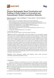
Fig. 2. A sequence of stripe patterns (left) is used to get a 3D point cloud of the patient (mid). Smooth Point cloud after removing inevitable outliers (right).
it can also be used to registrate the patient’s position, which will be explained below. 2.1 Preoperative tasks The first preoperative task consists of calibrating both the video projector and the CCD-cameras within the same coordinate system. This is accomplished by using a new calibration technique developed at the IPR and not published yet. In addition to defining the actual surgical plan with an appropriate planning system, another preoperative task consists of creating a file which helps to speed up the intraoperative registration and matching process. The file contains cubic - and therefore mostly resampled - voxels of the diagnostic image data, where each voxel stores a pointer to the nearest voxel of the patient’s skin surface (appropriate tools were also developed at the IPR). Its usage will be explained further below. 2.2 Intraoperative registration The most important step for transferring the planning data to the area of interest consists of finding the corresponding transformation from the planning system to the patient’s current position. Intraoperative registration of the patient normally makes use of artificial screw markers attached to the patient’s bone before acquiring the diagnostic image data, which remain there until the end of the surgical intervention. Visible in the image data and pointed at during the operation, they are used to calculate the transformation from the planning system to the intraoperative coordinate system. In developing the presented system, our goal was to registrate the patient’s position without attaching unpleasant screw markers to its bone in a precedent surgery. Thus, the essential part of the system is formed by a surface scanner which is used to generate a 3D point cloud of the patient’s skin surface immediately before the interventions starts (see [3] for a similar approach). This is accomplished by projecting a sequence of stripe patterns (coded light) on top of the region of interest with the aid of the integrated video projector (see Fig. 2. left). The corresponding images are acquired by the cameras, analyzed in consideration of shifting grey values and yield a 3D point cloud of the scanned area [4] (see Fig. 2. mid). After removing inevitable outliers, the resulting point cloud (see Fig. 2. right) can be matched to the preopera-
Fig. 3. Reconstructed surface from diagnostic image data overlayed with point cloud after calculation of initial position (left) and after fine tuning (right).
tively segmented surface of the diagnostic image data (CT, MRI) on which the surgical plan was defined. At this stage, most known matching algorithms require user interaction in order to find an adequate starting position for the matching process. Since matching algorithms commonly work by optimizing an appropriate failure function, this step ensures that the global (and not only the nearest local) optimum is found. In order to realize a system that needs no helping hands from outside, we developed a new matching algorithm which imitates the human strategy for the matching process of two corresponding surfaces. Actually, the search space for finding a rigid transformation from one coordinate system to another consists of six parameters (rotation and translation) which leads to an enormous calculation effort. But matching corresponding surfaces manually means shifting one on top of the other where the surfaces remain in contact in at least three points. This fact reduces the search space to three dimensions (rigid transformation in two dimensions). Implementing an algorithm that imitates the “touching” of surfaces would be very hard and time expensive in calculation. But the described process is equivalent to taking three fixed points of the scanned point cloud which are shifted around in a way that they always coincident with the surface reconstructed from diagnostic image data. The sum over all distances of the remaining points of the point cloud to the reconstructed surface is taken as failure function for finding a global minimum. Thereby, the above described voxel file serves as look up table for the distances. After an adequate starting position is found (see Fig. 3. left), the fine tuning is realized by using the Iterative Closest Point algorithm described in [5,6]. At this stage, the preoperatively calculated voxel file is used as look up table for the closest points (and not only their distances) on top of the reconstructed skin surface. The matching process provides an initial transformation Tini from the coordinate system of the diagnostic image data to the initial position of the patient (see Fig. 3. right). Since intraoperative conditions impede continuous scanning and in order to avoid attaching rigid fixations to the patient, succeeding registrations are performed by tracking markers pasted to the area of interest (see Fig. 4.). These are tracked and registered by analyzing corresponding images from the integrated cameras using Hough-transformations [7]. The first marker registration is performed simultane-
Fig. 4. Patient with projected operation planning symbols and tracking markers.
ously to the above described initial scan of the patient. This step yields a second transformation Tcur(t) mapping the patient’s initial to its current position. The global transformation Tglobal(t) = Tcur(t) Tini now allows to continuously transfer the surgical planning data to the patient’s coordinate system thus taking into account its actual position. The corresponding two-dimensional projector-bitmap which is projected onto the three-dimensional patient’s surface is edited in order to avoid or minimize distortion in areas of steep and bended surfaces. Maintaining lengths and angles, however, requires a triangulated surface (e.g. Delaunay-Triangulation) in order to predict and correct deformations by using normal vectors and other features. 3. Results and discussion The described method enables the surgeon to visualize planning data on top of any preoperatively segmented and triangulated surface (skin, bone, etc.) with direct line of sight during the operation. The system allows to meet occlusion by simply moving around the video projector to an appropriate position since changes of position of the video projector are equivalent to those of the patient. Furthermore, the tracking system allows dynamic adjustment of the data to the patient’s current position and therefore eliminates the need for rigid fixation with stereotactic frames or similar devices. The system is particularly attractive due to the fact that both the video projector and the cameras are multiply used (registration/visualization and registration/tracking respectively). All components of the above described system were developed at the Institute for Process Control and Robotics in Karlsruhe. The resolution of the currently used video projector is 800 x 600, whereby the field of projection covers an area of approximately 24 x 32 cm. Therefore, the achieved resolution lies between one third to one half of a millimeter and is presently superior to any head-mounted display. The achieved accuracy of the projected surgical planning data is about +/- 1 mm immediately after the initial scan of the patient (without tracking) and deteriorates to +/- 3 mm while tracking the patient’s position. The inaccuracy traces back to the minimum number of three tracked markers and the currently used camera resolution (744 x 576). Current efforts concentrate on improving the accuracy and on increasing the update frequency from 1.6 Hz just now to at least five updates per second. From the
point of view of project-involved surgeons, a vision frequency of 10 Hz and an accuracy of approximate 1 mm meets clinical demands. The described system distinguishes itself from other alternative technologies (headmounted displays, see-through glasses) by the fact, that it renounces both the attachment of unpleasant screw markers for navigation and the rigid fixation of the patient during the surgical intervention. Furthermore, the costs of the presented system are much lower than those for techniques based on expensive navigation systems. Another advantage of using a video projector to visualize surgical planning data is the fact that all surgically involved persons are able to share the same augmented reality view on the planning data and additional information without supplying them all with expensive head-mounted displays. In addition, the surgeon is not obliged to wear encumbering devices on his head and performs the surgical intervention without any interference of his general practice. Acknowledgement The research was funded by the special research grant Sonderforschungsbereich 414 “Information Technology in Medicine – Computer and Sensor Assisted Surgery” of the German Society for the Advancement of Scientific Research (DFG). References [1] [2] [3]
[4] [5] [6] [7]
S. Tang, C. Kwoh, M. Teo, N. W. Sing, and K. Ling, "Augmented Reality Systems for Medical Applications", IEEE Engineering in Medicine and Biology, pp. 49-58, May/June 1998. J. Münchenberg, J. Brief, H. Grabowski, C. Kübler, S. Hassfeld, J. Raczkowsky, U. Rembold, H. Wörn, "An Intuitive Operation Planning System for Craniofacial Surgery", Proceedings of 1. International Workshop on Haptic Devices in Medical Applications, pp. 94-101, June 1999. W. E. L. Grimson, T. Lozano-Pérez, W. M. Wells, G. J. Ettinger, S. J. White, R. Kikinis, "An Automatic Registration Method for Frameless Stereotaxy, Image Guided Surgery, and Enhanced Reality Visualization", IEEE Transactions on Medical Imaging, vol. 15, no. 2, pp.129-140, April 1996. H. Gärtner, "Quantitative 3D-Vermessung mit codierter Beleuchtung", Institut für Technische Optik, Universität Stuttgart, 1998. K. S. Arun, T. S. Huang, and S. D. Blostein, "Least-Squares Fitting of Two 3-D Point Sets", IEEE Transactions on PAMI, vol. 9, no. 5, pp. 698-700, 1987. J. M. Fitzpatrick, J. B. West, and C. R. Maurer, "Predicting Error in Rigid-Body Point-Based Registration", IEEE Transactions On MI, vol. 17, no. 5, pp. 694-702, 1998. C. F. Olson, "Constrained Hough Transforms for Curve Detection", Computer Vision and Image Understanding, vol. 73, no. 3, pp. 329-345, 1999.