AbstractâWith recent advocates on end-to-end congestion con- trol, we still observe lack of consideration of network congestion status in literature.
Prompt Congestion Reaction Scheme for Data Center Network using Multiple Congestion Points Shuo Fang, Chuan Heng Foh
Khin Mi Mi Aung
School of Computer Engineering Nanyang Technological University Singapore
Data Storage Institute A*STAR Singapore
Abstract—With recent advocates on end-to-end congestion control, we still observe lack of consideration of network congestion status in literature. Since end-to-end congestion control mechanisms are capable of gathering path load information through data paths, taking advantage of this information, network systems have potential capacity to react promptly in presence of congestion, especially for paths with multiple congestion points. In this paper, we design a congestion control scheme with consideration of multiple congestion points along data paths. Using an improved ECN mechanism, our scheme tunes source rate with feedbacks collecting from ECNs. We further improve our scheme with saturation detection and congestion prediction mechanisms. Simulation results show that our scheme works effectively. We evaluate our scheme and compare it with DCTCP, a recently proposed congestion control scheme for data center. In scenarios of multiple congestion points, our scheme exhibits better performance in terms of reaction time and stability. Index Terms—Congestion Control, Explicit Congestion Notification, Multiple Congestion Points
I. I NTRODUCTION In recent years, data center has scaled into large enterprise architecture for consolidation [1] with concurrent distinct services. At the same time, low cost commodity networking technologies are widely deployed within data center [2]. Given the requirement of low latencies [3], together with shallow buffer switches that data center provides, avoiding transient overloads in switch buffers for various data center applications is in a demand, and congestion control remains as one of the top concerns in improving performance of data center. With the arrival of Fibre Channel over Ethernet [4], on which storage traffic coexists with other types of traffic running at 10Gbps, proximately 40Gbps in near future, several requirements have been imposed on congestion control. In data centers TCP composes 99.91% of traffic [5], together with Layer 2 Ethernet deployment, applying TCP-like congestion control is considered as a potential solution for data center. However, existing congestion control schemes fail to satisfy data center requirements in several aspects. First, the transportation of storage traffic must be free of error as communicating parties perform no error handling, packet drop detection and failure recovery [6]. Thus, congestion control scheme in data center needs to ensure no loss transmission within Ethernet. Second, to avoid prohibitive cost, commodity switches with shallow buffers are commonly deployed in data centers. To prevent drops and also to ensure low latency transmission, it is essential to keep operating
points of switch queue lengths under a certain level. In addition, a new congestion control scheme is also supposed to take network congestion status into account. In the scale of a whole network, a higher number of congestion points indicates that more severe congestion happens in comparison with fewer points of congestion. In such a case, aggressive rate reduction should be applied to relieve the situation more effectively. On the other hand, to a specific sender, it stands more probability to be the source of congestion if its traffic has traversed through a data path with more congestion points. Given this observation, a more severe regulation on the sources traveling through over-congested paths, named as critical sources, takes effect more promptly than schemes which treat all sources equally. Thus requires a differentiated handling of critical sources and common sources in soothing buffer pressure. In this paper, we propose a congestion control scheme with ECN-like feedback piggybacking collection of network congestion status. In our proposed method, we make use of ECN field to record down each congestion point that a packet has passed. On receipt of an ECN marked packet, a receiver acknowledges its source and thus the source calculates a Congestion Status (CS) value, accumulates CS values within a certain time interval and adjusts its congestion window accordingly when a marked ACK arrives. The use of ECN-like feedback for congestion control is reasonable since our discussion is within data centers characterized by limited hop counts [7]. For most architectures, this number is limited within five hops between two communication hosts. Nowadays ECN-capable commodity switches are implemented in data centers, for example, Cisco Catalyst 4500 Series and Nexus 5000 Series. At the same time, ECN are commonly considered in congestion control as an approach of Active Queue Management in literature, such as [8], [9] and recently proposed [5]. While some achievement in congestion control has been reached, these works using a single bit of ECN are limited within merely binary indication of congestion. Besides, in [5] which has a similar target as our proposal, we find that it is not prompt enough for convergence due to prolonged RTT in case of queue buildup. The inadequate work for congestion control leaves space for further exploration. Our proposal adjusts congestion windows based on the information traversed along transmission paths, not only a single congestion point. In the next section, we provide related
work on congestion control in data centers. In section III, we describe our proposed method on congestion control with the assistance of ECN-like notification and window adjustments, and the scheme is further extended with saturation detection and congestion prediction mechanisms. We provide OMNET++ simulation results with a given scenario in Section IV. Finally, important conclusions are drawn in Section V. II. R ELATED W ORK Traditionally, FC technology avoids traffic congestion in a network on a buffer-to-buffer level using credit flow control. A sender can transmit the allocated amount of traffic, depending on the amount of credits issued by the receiver. Thus the credit allocation scheme prevents excessive incoming traffic and avoids traffic congestion. The introduction of FCoE has triggered demands for Ethernet congestion management. An immediate solution to enable equivalent credit-based flow control on Ethernet is to employ PAUSE mechanism [1]. It is suggested that a proper implementation of PAUSE mechanism may enable lossless transportation within an Ethernet network. In PAUSE mechanism, a downstream port issues a PAUSE frame to halt data transmission from the upstream port for a specified period of time to avoid traffic congestion. However, throttling transmission of an upstream port might lead to further congestions in its predecessors, and subsequently, traffic congestion can spread to all upstream ports even for those that do not transmit excessively. In other words, rather than dealing with source of the problem, this mechanism penalizes all sources when a traffic congestion event occurs. Additionally, due to bufferto-buffer control, congestion control and recovery are done hop-by-hop which takes some time to converge. To avoid congestion from spreading across the entire network, Cisco has proposed Ethernet Congestion Management (ECM), previously called BCN and now known as QCN [10] with significant improvements over BCN, as a Layer-2 endto-end congestion notification protocol. This mechanism aims to hold excessive traffic at the edge of a network. With fewer number of traffic volumes, the flows that caused congestion can be easily constrained and regulated. In ECM, a congested switch (congestion point) samples and sends feedbacks with its state towards the source of its congestion (reaction point). Upon receiving the feedback message, the reaction point controls its traffic volume from entering the network based on hardware rate limiters. By using an end-to-end congestion control, ECM directly deals with the source with excessive load rather than all sources. To reduce cost, ECM rate limiters group flows into flow set, resulting in flows that do not passing through the congested link reduce rate unnecessarily. Recently, a cross-layer congestion control, named data center TCP or DCTCP in short, operating at Layer-4 for data center networks has been proposed [5]. DCTCP proposes marking of ECN based on Layer-2 buffer state and a new rate adjustment scheme replacing AIMD. While DCTCP operates at Layer-4, with the introduction of ECN based on Layer-2 buffer state, it is capable of reacting to a potential congestion
Data Packets ECN=0
Congestion
ECN=1
Congestion
ECN=2
ACK ECN=2
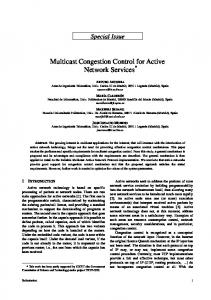
Fig. 1.
Illustration of message signaling.
before congestion occurs. However, sources merely based on ECN bit react identically towards congestions, regardless of number of congestion points on the data path. Moreover, flows coming through a congestion point reduce with the same proportion, though some may not be the source of congestion. In view of the need for a multiple congestion points supported congestion scheme and given abound TCP traffic and ECN-capable switch support in data centers, we propose using ECN-like multibit congestion indication with a new window adjustment scheme to provide data center congestion control. III. M ULTI C ONGESTION P OINTS C ONGESTION C ONTROL The proposed scheme is motivated by the slow convergence time in existing congestion control proposals. The goal of this proposed scheme is to achieve congestion control in a transient period of time. To this end, this proposed scheme achieves these goals primarily by reacting to congestion in proportion to the extent of network congestion and removing RTT factor in rate adjustment cycles. This proposed scheme uses a simple marking mechanism at switches as soon as their buffer levels exceed a preset threshold. A packet accumulates its ECN value each time it passes a congestion point. Its source reacts by reducing the congestion window by a factor depending on both the proportion of marked packets and the value of ECN feedbacks, namely the CS value. It is important to note that the key contribution here is not the computation law for CS value or the control law for the window size calculation. It is the inclusion of network congestion status in the feedback and continuous rate adjustment regardless of RTT. Thus, other control laws can be applied with our scheme as well. The entire process of our scheme includes signaling through data paths, echoing back from receivers, ECN calculation and rate adjustment on sources. In addition, we further design two mechanisms as optional implementation to improve overall performance. A. Signaling Congestion Signaling potential congestion mechanism is implemented at switches. As a data packet travels through its data path, each time it experiences a congestion point indicated by a queue length exceeding a preset threshold 𝑇 , its ECN value accumulates up to record number of congestion points on this certain path. On the receiver side, upon arrival of an ECN marked packet, it echoes back the number within its ACK. Figure 1 shows an illustration of the exchange of messages among network nodes. Corresponding header format is illustrated in Fig. 2 [11]. In our scheme, we utilize ECN field at IP header with two bits making four ECN codepoints, namely 00, 01, 10, 11. The value
0
14 4!bit version
4!bit header length
DS field
16!bit identification 8!bit time to live (TTL)
16
ECN field
8!bit protocol
31 16!bit total length (in bytes)
D M 0 F F
13!bit fragment offset 16!bit header checksum
32!bit source IP address 32!bit destination IP address …
Fig. 2.
Header format.
is saturated at 11, that means, when the ECN value adds up to more than three congestion points, the ECN value no longer accumulates and this codepoint of 11 indicates the maximum reduction of congestion window. B. Echoing Information By echoing information in packets, receiver side feedbacks the information through ACKs. As specified in RFC 3168 [11], there is a 3-bit ECN field in TCP header. Thus, a concise way is to make use of the last two bits to copy the information collected and acknowledge every incoming packet. However, in case of delayed ACK or cumulative ACK, the receiver can calculate an average number for ACKs. To be specific, it can keep ECN total by adding up ECNs, 𝐸𝐶𝑁𝑖 , in all the 𝑚 packets, average ECN total by 𝑚 and ∑𝑚round it off 𝐸𝐶𝑁𝑖 to an integer for the ECN feedback, 𝐹𝑒𝑐𝑛 = ⌈ 𝑖=1𝑚 ⌉. C. Reducing Rate Upon receiving a marked ACK, the source calculates a CS value according to the number it carries along and then reduces its congestion window with regards to an estimator ∑𝑛called 𝛼. The value of CS, 𝑉𝑐𝑠 follows the rule as 𝑉𝑐𝑠 = 𝑖=1 𝛽 𝑖−1 , where 𝑛 is the number of congestion points indicated in ACK. The source maintains an estimated congestion level of 𝛼 in a time interval, which follows 𝛼 ← (1 − 𝑔) × 𝛼 + 𝑔 × 𝑅, where 𝑅 is ratio of sum of 𝑉𝑐𝑠 over total∑number of ACK 𝑉𝑐𝑠 in previous time interval, namely 𝑅 = ∑ 𝐴𝐶𝐾 , indicating feedback information of network congestion, and 0 < 𝑔 < 1 is the weight given to new ratio against past 𝛼. For easy comparison, here we use the same law for ratio calculation as in [5]. We also cap 𝛼 at 2. Instead of following the calculation given in [5], which updates once for every window of data which is roughly one RTT time, in our scheme, the 𝛼 is updated within a certain interval 𝑡𝑖 (RTT in absence of queueing is a recommended value). This is because that RTT takes longer as queueing length increases, which creates latencies in presence of congestion. The parameter 𝛼 is used for reduction of congestion window every time an ACK is received by the source. While TCP always cuts its window size by a factor of 2 in response to a marked ACK or packet drop, here we use a more general reduction function by 𝑐𝑤𝑛𝑑 ← 𝑐𝑤𝑛𝑑 × (1 − 𝛼2 ). Smaller 𝛼 indicates a light congestion situation, thus congestion window reduces slightly. Higher 𝛼 indicates a more severe congestion, thus congestion window reduces significantly. In comparison with [5], our scheme with inclusion of network
congestion status and persistent adjustment period reacts faster in presence of severe congestion. D. Saturation Regulation and Congestion Prediction We include two optional mechanisms for our scheme, saturation regulation and congestion prediction. Our scheme provides a mechanism reacting to saturation congestion of a path. In other words, if all the switches on a path are congested, we define this path as a saturated path, the sources on such a path should cut their rates with maximum reduction. To identify saturation, at the initializing stage, the packet records switch number on the path in ECN field by increasing one each time it passes a switch, which is also saturated at 11. We set this acquired switch number at the receiver side, when the path experiences saturated congestion, indicating by a packet with an ECN equalling the preset switch number, the receiver sends out an ACK with a maximum ECN and thus incurs maximum reduction at source side. Besides, we use congestion prediction to avoid lags between congestion detection and rate reduction. As a signal travels first to its destination and then echoes back, it takes roughly a round-trip time for sources to get a feedback when congestion happens. During this lag, however, sources continue to inject traffic without rate control which exacerbates congestions. Hence, we design the congestion prediction mechanism to deal with this lag issue. Once a marked ACK arrives, the mechanism predicts that upcoming ACKs stand a high probability, 𝑝, to be marked for those unacknowledged packets, 𝑠𝑛𝑑 𝑢𝑛𝑎, on the path. Instead of relying on those ACKs to reduce rate, in our mechanism, it reduces congestion window size immediately. That means, the congestion window reduces continuously for the next 𝑝 ⋅ 𝑠𝑛𝑑 𝑢𝑛𝑎 packets. Later on, when a corresponding ACK arrives, the system checks and compensates on congestion window size in case that the ACK is not marked. To summarize this section, in implementation we can run our scheme with or without saturation and prediction mechanisms. Here, we denote the pure scheme as MTCP (Multiplecongestion-points TCP) and use MTCP Saturation and MTCP Prediction for the scheme with saturation mechanism or with prediction mechanism respectively. For the scheme with combination of both mechanisms, we denote it as MTCP Saturation & Prediction. IV. S IMULATION E XPERIMENTS Simulation implementation and experiments of our proposed scheme are conducted. We perform a number of experiments to demonstrate effectiveness and performance benefits of our proposed scheme, and compare it with DCTCP. The simulations are implemented by OMNET++ 4.0 simulator [12]. We follow the setup given in [5] to focus on situations with multi-congestion points and test performance of our scheme. Figure 3 depicts network topology used in our experiments. Data rate for all links is 1Gbps. In our scenario, three source groups, S1, S2 and S3, generate traffic to two destinations, R1 and R2. Group S1 and S3 each consists 10 senders (S1 1 to
8000
S3 G Group
S1 Group
7000
CWND (byte)
6000
……
…… …
5000 4000 3000 2000 1000 0
0
100
200
300
400
500
Time (ms)
Fig. 5. ……
…… …
R2 Group G
S2 Group p
Network topology for OMNET++ simulation.
160
160
120
120 Queue Length (packet)
Queue Length (packet)
Fig. 3.
80
40
0
80
40
0
100
200
300
400
500
0
0
100
Time (ms)
200
300
400
500
Time (ms)
(a) Queue length at Link 1. Fig. 4.
(b) Queue length at Link 2.
Queue length in the first experiment for our scheme.
S1 10 and S3 1 to S3 10), each sender transmits 10MB data to R1. There are 20 senders in group S2 (S2 1 to S2 20), each with 10MB data sending towards group R2 with 20 receivers. In this topology, there are two bottlenecks, the link connecting ES1 and CS, denoted as Link 1, and the link connecting ES2 and R1, denoted as Link 2. As a result, group S1 experiences two congestion points, while group S2 and S3 only travel through one congestion point respectively. We conduct two simulation experiments. We target at stability test of our proposed scheme in the first experiment, and performance comparison with DCTCP in the second experiment. In the first experiment, we run the simulation for only the original scheme without the two optional mechanisms. We set a threshold 𝑇 with 20 packets in switches and all test parameters are listed in Table I. With a simulation run of 500ms, both queues at the congested switches obtain their steady state as shown in Fig. 4, as Fig. 4(a) shows queue length at Link 1 and Fig. 4(b) shows queue length at Link 2. We can see that, Link 1 maintains a higher queue length in comparison with that of Link 2, due to its longer reaction time with further distance to the destinations and longer adjustment time for tuning more sources than those of Link 2. TABLE I PARAMETER SETTING Name 𝑇 𝑡𝑖 𝛽 𝑔 𝑝
Congestion window evolution at an S1 sender.
Experiment 1 Our Scheme DCTCP 20 packets 20 packets 20𝜇s RTT 0.9 0.05 0.05 -
Experiment 2 Our Scheme DCTCP 10 packets 10 packets 20𝜇s RTT 0.9 0.05 0.05 0.8 -
We randomly select a sender in S1 group and show its congestion window evolution in Fig. 5. We note that all other senders share a similar congestion windows evolution. In the second experiment, we run not only the pure scheme, but also two optional mechanisms, separately and in combination. Their performances are compared with DCTCP. In this experiment, we focus on steady state queue length, the highest value of a queue length, and the fraction that a queue length exceeds the steady state queue length. In the first issue, steady state queue length is studied to indicate the system operating point. In the second issue, the highest queue length is illustrated to indicate the chance of potential packet drop. For example, if a buffer can hold 200 packets, the scheme reporting a value higher than this will likely to experience packet loss. The last issue is the convergence time to reach a steady state. Here we define this proportion of queue length higher than steady state queue length as exceeding fraction size. A less fraction indicates a faster time to converge and a more stable system. We list parameters used in our experiments in Table I. From the first experiments, we can see that queue length may soar to a high level before control schemes take effect. Given the fact that potential packet drop occurs mainly in this unstable period, to focus on oscillations and to better compare performance with DCTCP, we show simulation results of their CDFs for the first 100ms, as shown in Fig. 6 and Fig. 7. Figure 6 demonstrates the results at Link 1. The steady state queue length in our scheme is around 40 packets compared to around 50 packets in DCTCP. Queue length in our scheme goes as high as around 140 packets, while it soars over 180 packets in DCTCP in Fig. 6(a). In terms of exceeding fraction size, it is shown that in our scheme it holds about 0.1 and in DCTCP it takes up to 0.34 at Link 1. Thus our scheme exhibits a lower operating point, faster convergence time and a lower chance of packet drop. Since the route from Group S3 to R1 leads to the saturated path in our simulation setup, the saturation implementation does not create obvious impact on queue length at Link 1 as shown in Fig. 6(b) and Fig. 6(d). We can see in Fig. 6(c) that the queue length is pushed back to a little over 20 packets, though the highest queue length is moved up a bit to around 150 packets in our scheme. The results also show that the exceeding fraction size keeps the same. Therefore, if we expect to have a lower operating point at Link 1 and the system is insensitive to packet drop around 150 packets, say if the system has a much higher buffer size, it is recommended to include congestion prediction mechanism in the operation.
1 0.9
0.8
0.8
0.8
0.8
0.7
0.7
0.7
0.7
0.6 0.5 0.4
0.6 0.5 0.4
0.5 0.4
0.3
0.3
0.2
0.2
0.2
0
0.1
DCTCP MTCP 0
50
100 Queue Length (packets)
150
0
200
0
50
100 Queue Length (packets)
150
0
200
0.5 0.4
0.2 0.1
DCTCP MTCP Prediction Only 0
(b) MTCP Saturation. Fig. 6.
0.6
0.3
0.1
DCTCP MTCP Saturation Only
(a) MTCP.
50
100 Queue Length (packets)
150
0
200
(c) MTCP Prediction.
1 0.9
0.8
0.8
0.8
0.8
0.7
0.7
0.7
0.7
0.4
0.6 0.5 0.4
0.6 0.5 0.4
0.3
0.3
0.3
0.2
0.2
0.2
0.1 0
DCTCP MTCP 0
50 100 Queue Length (packets)
(a) MTCP.
150
0.1 0
DCTCP MTCP Saturation Only 0
50 100 Queue Length (packets)
150
(b) MTCP Saturation. Fig. 7.
Cumulative Fraction
1 0.9
Cumulative Fraction
1 0.9
0.5
50
100 Queue Length (packets)
150
200
Queue length CDF at Link 1 compared with DCTCP.
1
0.6
DCTCP MTCP Saturation & Prediction 0
(d) MTCP Saturation & Prediction.
0.9
Cumulative Fraction
Cumulative Fraction
0.6
0.3
0.1
Cumulative Fraction
1 0.9
Cumulative Fraction
1 0.9
Cumulative Fraction
Cumulative Fraction
1 0.9
0.5 0.4 0.3 0.2
0.1 0
0.6
DCTCP MTCP Prediction Only 0
50 100 Queue Length (packets)
(c) MTCP Prediction.
150
0.1 0
DCTCP MTCP Saturation & Prediction 0
50 100 Queue Length (packets)
150
(d) MTCP Saturation & Prediction.
Queue length CDF at Link 2 compared with DCTCP.
The results at Link 2 is shown in Fig. 7. For both pure MTCP and DCTCP, we see a steady state queue length at around 20 packets. The highest queue length is below 70 packets in our scheme as compared to over 120 packets in DCTCP. Moreover, it takes roughly around 0.08 on the exceeding fraction size in our scheme at Link 2, while in DCTCP the fraction is about 0.2 in Fig. 7(a). With the implementation of saturation mechanism, we see that the steady state queue length has been pushed further back to around 10 packets, but not very stable as shown by the slope in Fig. 7(b). In this mechanism the highest queue length is lowered to only 50 packets and the exceeding fraction size is reduced to only about 0.03. With the implementation of prediction mechanism, the steady state queue length is straighten up also at 10 packets, however, it reaches a higher value of highest queue length and more unexpected fraction size. The combination of the two improves performance in all three aspects and gives a better results as shown in Fig. 6(d). It exhibits a reaction time three times faster with an unexpected fraction size of 0.05 compared to 0.2 in DCTCP. V. C ONCLUSIONS In this paper, we proposed a congestion control scheme for network with multiple congestion points. Our proposed method considers using a different ECN mechanism for congestion feedback information. Our work aims at accelerating reaction time in presence of congestion by the capacity of ECN feedbacks to provide network congestion status. We presented stability and effectiveness of our work in OMNET++ simulations, with results showing that our scheme reacts promptly to network congestion. This method has the capacity to react within 25% time compared to DCTCP towards congestions. This is achieved by penalizing more on the sources whose
traffic travels through multiple congestion points. Moreover, we also studied the performance of saturation and prediction mechanisms, simulation results show that the system runs at a much lower operating point and reacts even faster. R EFERENCES [1] G. Silvano and D. Claudio, “I/O consolidation in the data center. A complete guide to data center Ethernet & fibre channel over Ethernet,” 2009. [2] M. Al-Fares, A. Loukissas, and A. Vahdat, “A scalable, commodity data center network architecture,” in Proceedings of the ACM SIGCOMM 2008 conference on Data communication. ACM, 2008, pp. 63–74. [3] S. Kandula, S. Sengupta, A. Greenberg, P. Patel, and R. Chaiken, “The nature of data center traffic: measurements & analysis,” in Proceedings of the 9th ACM SIGCOMM conference on Internet measurement conference. ACM, 2009, pp. 202–208. [4] “Fibre Channel over Ethernet in the data center: an introduction,” Available at http://www.fibrechannel.org, Fibre Channel Industry Association, 2007. [5] M. Alizadeh, A. Greenberg, D. Maltz, J. Padhye, P. Patel, B. Prabhakar, S. Sengupta, and M. Sridharan, “Data center tcp (dctcp),” pp. 63–74, 2010. SAN and LAN Infrastructure with [6] “Converging Fibre Channel over Ethernet,” Available at http://download.intel.com/support/network/sb/ciscointelfcoewhitepaper.pdf, Cisco and Intel technical report. [7] “IEEE. 802.1Qbb - Priority-based Flow Control,” Available at http://www.ieee802.org/1/pages/802.1bb.html, IEEE Standard for Local and Metropolitan Area Networks - Virtual Bridged Local Area Networks - Amendment2008c, 2008. [8] S. Kunniyur and R. Srikant, “End-to-end congestion control schemes: Utility functions, random losses and ecn marks,” Networking, IEEE/ACM Transactions on, vol. 11, no. 5, pp. 689–702, 2003. [9] D. Katabi, M. Handley, and C. Rohrs, “Congestion control for high bandwidth-delay product networks,” vol. 32, no. 4, pp. 89–102, 2002. [10] R. Pan, B. Prabhakar, and A. Laxmikantha, “Qcn: Quantized congestion notification,” cited in www. ieee802. org/1/files/public/docs2007/auprabhakarqcn-description. pdf. [11] “The Addition of Explicit Congestion Notification (ECN),” Available at http://www.faqs.org/rfcs/rfc3168.html, Internet Engineering Task Force (IETF), 2001. [12] “OMNeT++,” http://www.omnetpp.org.