unearthed and the same testing voltage is through all the winding), while during the operation the voltage is evenly distributed along the winding from zero to.
Propagation of partial discharge pulses in winding
11
PROPAGATION OF PARTIAL DISCHARGE PULSES IN WINDING Karel Záliš Czech Technical University in Prague, Faculty of Electrical Engineering, Department of Electrical Power Engineering Technicka 2, CZ 16627 Prague 6, Czech Republic Phone:+420 224 352 369, fax:+420 233 337 556, E-mail: zalis@ fel.cvut.cz Summary A lot of measurements of the attenuation of partial discharge pulses on the model of winding was realized in the High Voltage Laboratory of the Czech Technical University in Prague. Current pulses from a charge calibrator were injected into different parts of winding and both the distortion of the charge and their deformations at the end terminals were observed and evaluated. It was confirmed that the apparent charge of a partial discharge, as a diagnostic parameter, is not relatively very sensitive, comparing to other diagnostic parameters, e.g. to the size or the shape of a partial discharge current pulse. The charge of the partial discharge current pulse on terminals was integrated by means of three different methods. It was found that the attenuation of the partial discharge pulse is significant. It was confirmed by all three evaluating methods with similar results. Furthermore, a measurement both of the attenuation of pulse and changes of partial discharge charge was realized on different types of winding. It resulted in the fact that the attenuation of the partial discharge charge on different types of winding depends on the winding parameters.
1. INTRODUCTION At present the majority of diagnostic measurements of insulating systems of electric machines and high voltage equipments is made in off-line mode, i.e. on a detached machine during its check-up or repair, usually using the external adjustable source of a testing voltage. The main advantage of an on-line measurement, i.e. when the machine is working, is the possibility of finding the changes of insulation system immediately, which gives enough time for observing a defect progress and repair planning. When measuring off-line, the majority of insulation systems is under higher voltage than the operating voltage is (the winding is unearthed and the same testing voltage is through all the winding), while during the operation the voltage is evenly distributed along the winding from zero to the rated voltage. The method of measuring partial discharge seems to be a suitable diagnostic method for on-line type of measuring. For the operation use it is necessary to solve some of its problems, however. Partial discharges often occur in places unapproachable for straight measurements, e.g. in the windings of electric machines. Current pulse, arisen from the partial discharge, is expanding from the place of its rise (usually from a vacuole in a winding insulation) and it is measurable only at the winding outlet - at machine terminals. When expanding through the winding the pulse distorts - its amplitude decreases, its shape changes and there is a possibility of a damped oscillation of the pulse. Therefore, we do not measure a real charge of the partial discharge in an insulation vacuole, but the apparent charge, which can be different. The winding of the machine also has, besides distributed winding inductance and winding resistance, capacities between turns and coils and also between the winding and earthed
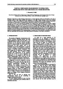
construction. At operation frequency 50Hz, the capacity resistance 1/ C, dependent on these capacities, is significantly high, and therefore we can ignore capacity currents, as they are imperceptible comparing to the currents passing through small inductive and ohmic types of winding resistance. On the other hand, high frequencies the situation is completely different, while passing through winding, the ratio of higher harmonics in the pulse decreases, which results in a change of the pulse shape. In the Laboratory of High Voltage at the Czech Technical University in Prague several measurements were realized to determine how much the value of basic diagnostic parameter, i.e. the apparent charge, changes itself while passing through the winding. Measurements were carried out on a model of a transformer winding which had three windings: coils A, B (one-layer windings with different number of turns) with 11 taps, and coil C (a plate winding) with 22 taps, see Fig. 1. Coil D has not been searched by reason that has not internal terminals. A commercial calibrator TETTEX, type 9216 (pulse frequency 100 Hz, start-up time about 100 ns) was used for the simulation of partial discharges in the winding. It imputed current pulses into the internal taps of the winding. Having passed the winding, the pulses were detected at the end of the winding (in the end terminals of the winding) and were evaluated by the digital oscilloscope LeCroy, type 9350 (bandwidth 500 MHz, sampling 2 GS/s for a single signal) with built-in mathematical functions. A sample of the evaluated partial discharge pulse is on Fig. 2, where on the horizontal axis is time and on the vertical axis are the partial discharge current of the partial discharge pulse (curve 1), the absolute value of this current pulse (curve A) and the integral of this absolute value of current pulse (curve C).
Advances in Electrical and Electronic Engineering
Winding A
12
Winding B Winding C
Winding D
Fig. 1 Model of transformer windings
oscilloscope, Rm is a load resistance; L is the total length of the winding, x represents the length of the winding, which the pulses of partial discharges pass through (It is determined by the position of the calibrator KG).
1 ... i (t) A ...i(t) C ... i(t)dt
2. EVALUATION OF PARTIAL DISCHARGES
Fig. 2 Measured and evaluated values of the partial discharge current pulse
Passing through the winding significantly influences the shape of the partial discharge pulse. It can be distorted and then its apparent charge is very difficult to evaluate (i.e. in the pulse oscillation). Our aim was to find out which parts of the distorted current pulse of the partial discharge are the most suitable for the evaluation, so that the apparent charge of the pulse would show the smallest change. i q1
x
q3
L Rm
KG
t
OSC
Fig. 3 Diagram of the measuring circuit
The circuit diagram in Fig. 3 shows how the measurement was made, where OSC is a digital
q2
q4
Fig. 4 Distorted current pulse of partial discharge
Therefore we used following three methods for evaluating the distorted current pulse of the partial discharge (see Fig. 4, where on the horizontal axis is time, on the vertical axis is the partial discharge current and hatched surfaces are partial discharge charges): a) Only the first wave of pulse was evaluated, i.e. q = q1.
Propagation of partial discharge pulses in winding
13
b) Only waves of the same polarity were evaluated (in effect, only first two positive parts of the pulse), i.e. q = qp = q1+q3. c) All parts of the wave (regardless the polarity) were evaluated, i.e. q = qs = |q1|+ |q 2|+ |q 3|+ |q4|.
Measurements were performed on winding A (load resistance R m = 100 k ) and measured values were transformed to the chart, see Fig. 5, where the relative distance is on the horizontal axis and the measured partial discharges are on the vertical axis.
100
80 q1 qp qs
q [%]
60
40
20
0 0
10
20
30
40
50
60
70
80
90
100
x/L [%]
Fig. 5 Evaluation of attenuation of partial discharge pulse by different methods
We can see that the charge decreases while passing through the winding, when passing the 40 per cent of the winding it decreases to about 80 per cent of its original value, when passing 70 per cent of the winding to about 60 per cent of the value, when passing 90 per cent of the winding to about 25 per cent of its original value. This fact was confirmed with all the methods of evaluation. The differences among the methods of evaluation of the apparent charge of the distorted partial discharge were not significant. Differences in values obtained in method a), i.e. q1 (this method is used by the majority of commercial measurers) and in method b) i.e. qp are max. 7 per cent, between q 1 and qs (method c) is max. 5 per cent, which is quite acceptable for the operation measurements of the partial discharge deviation. As the evaluation of qp is relatively difficult (it is necessary to use the per-partes method), for practical measurements and evaluations methods either the method q1 (i.e. evaluation of the partial discharge from the integration of the first wave of the current pulse only) or the method qs, where the partial discharge q is determined from relation:
q=
i(t ) dt =
1 Rm
u m (t ) dt .
This method, i.e. method qs , is more suitable in our case and that is why this method was used for an evaluation of the attenuation of partial discharges on different windings. 3. ATTENUATION OF THE APPARENT CHARGE ON DIFFERENT WINDINGS T o be able to find out the influence of the type of winding and winding parameters on the attenuation of the apparent charge we made measurements of the pulse attenuation and changes of the charge of partial discharges on different windings. Measured values of the apparent charge dependent on the partial discharge pulse passing through three different windings were plotted into the graph in Fig. 6, where the relative distance is on the horizontal axis and the measured partial discharges are on the vertical axis. We can see that the attenuation of the apparent charge of the partial discharge on different windings is similar and depends on winding parameters. This stands for all types of windings. In case of the plate winding (winding C) extra resonances and reflections occurred.
Advances in Electrical and Electronic Engineering
14
120 100
Winding A Winding B
q [%]
80
Winding C
60 40 20 0 0
10
20
30
40
50
60
70
Fig. 6 Attenuation of the apparent charge on different windings
ACKNOWLEDGMENTS I would like to thank very much to students of the Department of Electrical Power Engineering of the Czech Technical University in Prague, Faculty of Electrical Engineering for the cooperation at the measurement tests. The Department of Electrical Power Engineering of the Czech Technical University in Prague and the Czech Republic Grant Agency (grant No. 102/02/0105) financially supported this project. REFERENCES [1] Gulski E. and Kreuger F. H.: Computer-aided recognition of discharge sources, IEEE Trans. of Electrical Insulation, vol. 27, No. 1, pp. 82-92, 1992. [2] König D. and Rao N.: Partial Discharges in Electrical Power Apparatus, vde verlag, 1993. [3] Florkowska B.: Partial Discharges in High-voltage Insulation Equipment - Analysis of Mechanisms, Forms and Patterns (in Polish). Wydawnictwo IPPT PAN, Warszawa (Poland), 1997. [4] Florkowski M.: Partial Discharge Image Recognition Using Neural Network for High Voltage Insulation Systems. Wydawnictwa AGH, Krakow (Poland), 1996. [5] Šandrik P., Zlatovský J.: Insulating System and Diagnostic Quantities. Proceedings of the Scientific Colloquium on High Voltage Engineering, Košice (Slovakia), 2002, pp. 15-18. [6] Kolcunová I. and Krš ák I.: Diagnostika elektrických to ivých strojov metódou iastkových výbojov (Diagnostics of rotating electrical machines by partial discharge method). Proceedings of the ELOSYS Conference, Tren ín (Slovakia), 1997, pp. 83-85.
80 90 x / L [%]
100
[7] Cimbala R.: Non Destructive Diagnostics for Insulation Systems of HV and UHV Equipment. Proceedings of the 13th International Conference DISEE 2000 (Dielectric and Insulating Systems in Electrical Engineering), Bratislava (Slovakia), 2000, pp. 26-28. [8] Kolcun M.: Optimalizácia prevádzky elektrární v elektriza nej sústave (Optimization of power station operation in electricity supply system). Vydavate stvo Elfa, Košice (Slovakia), 1999. [9] Záliš K., Beranová L., Prskavec L. and T mínová R.: Some Problems with Partial Discharge Measurement in On-line Mode. Proceedings of the 8th International Conference on Optimization of Electrical and Electronic Equipment (OPTIM 2002), Vol. I (Electrotechnics), Brasov (Romania), 2002, pp. 157-161. [10] Kolcunová I. and Krš ák I.: Types of partial discharges and their recognition in insulation of high voltage rotating machines. Proceedings of the Scientific Conference, Oradea (Romania), 1997, pp. 67-70. [11] K. Marton: Imperfect point in insulating system as a radiator of electromagnetic signal. Proceedings of the Conference DISEE ’98 (Dielectric and Insulating Systems in Electrical Engineering), Bratislava and Casta-Pila (Slovakia), 1998, pp. 3033. [12] Karas J.: Controlling and analyzing software for partial discharge measurement system. Proceedings of the Workshop 2000, part B, Prague, 2000, p. 470.