EMC’09/Kyoto
23R3-5
Proposed methods to measure the Shielding Performance of PCB level enclosures Filip Vanhee #1,2, Bjorn Vanhee#1, Johan Catrysse #1,2 ,He Yuhui#3, Andy Marvin#3 #1
Industrial Sciences and Technology, Katholieke Hogeschool Brugge-Oostende Zeedijk 101, B-8400 Oostende, Belgium #2 ESAT-MICAS, Katholieke Universiteit Leuven Kasteelpark Arenberg 10, B-3001 Heverlee, Belgium
[email protected]
[email protected]
[email protected]
#3
University of York, York, UK
[email protected] [email protected]
-
Abstract—PCB-level shielding enclosures differ from the other shielding products in several aspects due to their small volume and therefore pose new challenges to the evaluation of performance. This paper describes several possible approaches to accomplish fast and reliable shielding effeciteness (SE) values.
unlike the larger enclosures primarily applied to protect the whole system, they are commonly used to cover only one part of the circuit board and are usually enclosed by a larger external enclosure. When considering the performance, the near field isolation in such a high Q environment should be stressed.
I. INTRODUCTION Shielding technology is becoming increasingly important in the electronics industry with the trend to the complex integrated circuits and faster clock frequencies. General rules such as good grounding, keeping noise sources away from large dimension metal components and reducing the length of transmission lines are more and more difficult to meet due to the increased demand for integration. Shielding enclosures are therefore often employed to reduce the electromagnetic interference (EMI) caused by a noise source. In particular, the surge of wireless communication and mobile telephone systems, in which portability and miniaturization is critical, necessitates the use of PCB-level shielding products. For both manufacturers and users of these products, information of their performance in practical applications is highly desirable. Shielding Effectiveness (SE) is widely employed to characterize the performance of shielding materials and enclosures. Standards concerning the SE of enclosures larger than 2m are setup [1], middle sized enclosures from 0.1m to 2m are also studies extensively [2],[3],[4]. Nevertheless, there are still no standards and little consensus evaluating the performance of PCB-level shields whose dimensions are extremely small. PCB-level shielding enclosures have several characteristics in contrast with the other enclosures: -
they are incomplete enclosures as the PCB constitutes one of the faces of the enclosure [5]
-
the greatest dimension is usually smaller than 50mm; the distance from the protected circuits to the shielding walls is extremely short so that the interaction between them is not negligible
II. ANALYSIS OF EXISTING APPROACHES The anechoic chamber is able to provide a thorough measurement of the electromagnetic field radiatedby equipment under test (EUT). A measurement antenna van be put into the chamber to measure the intensity of electromagnetic field radiated by the enclosure and then contrast with that measurement by the antenna without the enclosure. The SE could be defined as the maximum decibel ratio of the two values of all measured points. The validity of this approach relies on the number of positions examined as well as the complexity of the field pattern. For PCB-level enclosures which are always perforated with arrays of apertures which complicate the field pattern and polarization considerably, a large time is required to find out the real vulnerable point. In addition, the reliability of this measurement is compromised by the ideal test environment that is very different to that of practical working conditions for PCB-level enclosures. The impedance measurement method [6] provides a relatively simple and fast way to compare the performance of small enclosures. This method basically examines the variation of the S11 parameter of an embedded antenna in the enclosure with a network analyzer. From the theory of power balance, the power radiated is divided into three parts: leaked power, reflected power and power loss due to an imperfect conductor. The increase of SE implies that the leaked power through the enclosure is reduced. The reflected power will therefore increase. It can only be used to give a rough indication of the SE of low performance enclosures
Copyright © 2009 IEICE
689
EMC’09/Kyoto
23R3-5
The so-called worst-case shielding effectiveness [7] focuses on the isolation on the same board, by short-circuiting the metal can with the signal generator. This method may examine the extreme situation, but the comprehensive information was not presented. Moreover, this approach depends enormously on the coupling paths and directions. Small variations may induce significant differences.
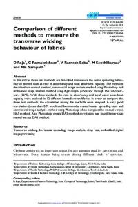
Several near-field coupling paths on the same board were established. Two identical 10mm height monopoles but with different orientations were used, and two other rectangular loops were also installed. The small enclosures studied in this work were from Micro Precision Ltd, with a size of 40mmx30mmx10mm, perforated with different sizes of small holes. The complete set of PCB and enclosures is shown in Fig. 2.
III. PROPOSED NEW APPROACHES In this section, several proposals are presented, using different approaches. They have been developed by the EMC research groups of the University of York (UK) and the FMEC laboratory of KHBO (BE). The work reported here is incomplete and is intended to inform the work of the IEEE Working Group revising IEEE Std. 299TM on the measurement of shielding effectiveness of enclosures. It must be noted that in the framework of this paper, only a summary is results is presented. More details can be found in the literature [8], [9]. A. Method using a reverberation chamber Reverberation chamber practice has developed rapidly recently and is used in various EMC measurements [8]. More and more EMC laboratories now use this powerful tool. The reverberation chamber method has several advantages in evaluating the SE of PCB-level shielding. Two radiators were constructed on a printed circuit board (PCB) to serve as the EMI sources for experiment. An array of 5mm-diameter holes with constant separation was drilled through the PCB. The holes were plated through with copper to ensure the ground was perfect and minimize leakage via the connectors. SMA sockets were then inserted into the holes and soldered on one side of the PCB as a socket for signal source. A conductive line was imposed on two connectors to form a 25mmx7mm rectangular loop as the first source which was loaded with a 50 Ohm SMA load. A single bent monopole 3mm above the board and 10mm long was set up on another similar PCB to act as the other source. The layout on the board is illustrated in Fig. 1.
Fig. 2. Loop source and monopoles, with enclosures
Different approaches can be used for setting up a measuring configuration in a reverberation chamber. One is using a horn antenna at higher frequencies, another one is using a small monopole probe, mounted on one of the walls of the reverberation chamber. The latter one is shown in Fig. 3.
Fig. 3. Configuration of a mode stirred reverberation chamber, using a monopole probe in the frequency range 1 – 6 GHz.
Fig. 4. SE for an enclosure “big hole”
Fig. 1. Geometry of the two PCBs
Copyright © 2009 IEICE
690
EMC’09/Kyoto
23R3-5
Fig. 4 shows the measured SE value for a typical enclosure with rather big holes (2.2mm diameter in a grid of 2.5mm). As internal antenna, the loop antenna was used. More details on the effect of the use of another antenna, the size of the reverberation chamber, etc. … are found in [8].
The idea behind this concept is that both ICs and the CANs needed to minimize EMI effects, are characterized using a similar test set up, and that the SE values obtained will give performance factors that can be directly integrated in the design process of PCB boards.
B. Near field coupling method The ability of the PCB-level shielding enclosure to isolate the neighboring components was tested by connecting the port2 of the VNA to the near field coupling paths on the PCB instead of the standard antennas. The performance of the same enclosure is shown in Fig. 5.
Fig. 7. Microstrip (upper), covered by the PCB-level enclosure (middle) and the stripline (lower) of this set up
The main advantage is that the microstrip, acting as the internal antenna in the enclosure, represents a wide band matched (to 50 Ohm) structure. The small CAN used for this purpose is from Laird Technologies and the size is 52mmx48mmx14mm.
Fig. 5. Near-field evaluation of PCB-level enclosures
These results indicate that the reverberation chamber approach is also a good indication of the ability of PCBlevel shielding enclosures to isolate the internal devices in a cabinet to the ambient circuits.
C. Microstrip/stripline approach Recently, a method has been proposed by Koerber for the characterization of integrated circuits (IC) using a stripline method [9]. The principle is shown in Fig. 6. Fig. 8. Measurement of the induced signal in the stripline: upper trace for the naked microstrip (no CAN) and lower trace for the shielded microstrip
Measuring results up to 3 GHz are shown in Fig. 8, and the difference between both traces represents the SE value, which is about 30-40 dB for this specific enclosure. First tests up to 8 GHz suggests the ability of the set up, and even up to higher frequencies. The method looks well promising, and the setup does not require large space or special measuring rooms.
Fig. 6. Principle of stripline setup for characterization of IC
Based on the same approach, a method is proposed to characterize PCB-level enclosures. Instead of the IC, a microstrip is used as internal antenna, and the small enclosure is mounted over the microstrip. The concept is shown in the next figure 7.
Copyright © 2009 IEICE
691
D. Modified IEEE 299 method (or MIL STD 285) A well established method for the characterisation of larger enclosures is described in the standard IEEE Std. 299TM. A modified version is widely used for the characterisation of shielding materials.
EMC’09/Kyoto It is based on performing measurements using a large metal box, where a window is made in one of the walls. By placing an antenna inside and outside the box, transmission measurements are made between both antennas. By comparing the measurements with the open window, and the window covered with the material under test, the SE value of the material is obtained. The method is sketched in the next Fig. 9.
23R3-5
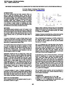
The measurements were performed in the frequency range from 1GHz upto 6 GHz, and are given in Fig. 12. The upper trace is the signal level for the open CAN, the middle trace is the signal level for the closed CAN, and the lower trace is the noise floor of the measuring system.
Fig. 12. Measuring results for the modified IEEE 299 method
From these measuring results, an estimate of 30-40 dB can be made for the SE value of the PCB and the CAN, which is in good agreement with the stripline method.
Fig. 9. Basic principle of the modified IEEE 299 method for the SE measurement of shielding materials
By covering the window of the metal enclosure with a PCB carrying the small CAN, the related shielding may be measured using this same concept. The open window, showing the horn antenna inside the large enclosure is shown in Fig. 10.
IV. CONCLUSIONS This paper is intended to provide initial examination of evaluation of PCB-level shielding enclosures. Several possible approaches are described. The work reported here is incomplete and is intended to inform the work of the IEEE Working Group revising IEEE Std. 299TM, on the measurement of shielding effectiveness of PCB-level enclosures. The methods described in section III.A and B were developed by the EMC group of the University of York (UK). The methods described in section III.C and D are developed by the FMEC/EMC group of KHBO (BE). REFERENCES
Fig. 10. Large open window of the metal enclosure, and showing the horn antenna inside the enclosure
A massive copper plate, with a small opening, is mounted on the large window. On this plate, the PCB and its small CAN is mounted. The next pictures show the open CAN, and the closed CAN, as mounted in the measuring set up.
Fig. 11. Open CAN (left) and closed CAN (right) as mounted on the PCB, which is fixed on the large enclosure
[1] Standard method for measuring the effectiveness of electromagnetic shielding enclosures, IEEE Std. 299TM, IEEE, Piscataway, NJ [2] A. Marvin et al., “A new proposed definition and measurement of the shielding effectiveness of equipment enclosures”, IEEE Transactions on EMC, vol. 46, No. 3, Aug. 2004 [3] D. Hill et al., “Aperture excitation of electrically large, lossy cavities”, IEEE Transactions on EMC, vol. 36, pp. 169-177, Aug. 1994 [4] M. Robinson et al., “Analytical formulation for the shielding effectiveness of enclosures with apertures”, IEEE Transactions on EMC, vol. 40, pp. 240-248, Aug. 1998 [5] T. Clupper, “A new PCB-level shielding technology”, Plymouth Meeting PA: Interference Technologies, 2003, pp.187-195 [6] B. Cromarthy and R. Paknys, “Shielding effectiveness diagnostics using a scalar network analyzer”, Proceedings of IEEE Int. Symp. on EMC, Montreal, Aug. 2001 [7] Aki Hekalla and Timo Tarvainen, “High Frequency Shielding Effectiveness of small metal CANs”, Proceedings EMC Europe 2002, Sorrento, Sept. 2002, pp. 327-332 [8] He Yuhui and Andy Marvin, “An investigation of the shielding performance of PCB-level enclosures using reververation chamber”, Proceedings IEEE Int. Symp. on EMC, Hawai, Aug. 2007 [9] B. Koerber et al., “IC-stripline: a new proposal for susceptibility and emission testing of ICs”, Proceedings EMCcompo 2007
Copyright © 2009 IEICE
692