PROTOCOL FOR STREAMING COMPRESSED 3-D ANIMATIONS OVER LOSSY CHANNELS Ghassan Al-Regib∗ , Yucel Altunbasak∗ , Jarek Rossignac∗∗ , and Russell Mersereau∗ ∗
Center for Signal and Image Processing Georgia Institute of Technology Atlanta, GA 30332-0250 E-mail:{gregib,yucel,rmm}@ece.gatech.edu
ABSTRACT In this paper, we propose a protocol for efficient streaming of 3-D animations over losssy channels. In order to improve the expected quality on the client’s side, we first transmit a crude model of the 3-D mesh, of its texture, and of its immediate evolution. We endow this data with significant error-protection against transmission error. Then we transmit a series of upgrades that refine the accuracy of the model and/or of the animation. These are encoded with lower levels of error protection that is proportional to their impact on the quality of the upgraded animation. We propose the following types of upgrade chunks: selection of a subset of vertices, adjustments of the accuracy of the positions of the selected vertices, connectivity refinements, motion adjustments of the selected subset of vertices, adjustments of the accuracy of the texture coordinates of the selected vertices, and upgrade of the quality of the texture. Finally, given the allocated bit-budget, we determine the optimal number of both source and channel coding bits assigned for each chunk to maximize the animation quality on the client’s side. The optimization takes into account both the bandwidth and the error characteristics of the channel. 1. INTRODUCTION Nowadays, Internet users can communicate visually as well as audibly via video conferencing. More recently, an increasing number of Internet applications use 3-D models so that users can meet and interact with each other within virtual cyber worlds. Interactive animation is the next important step. The possibility of accessing 3-D animations over Internet connections for interactive viewing will impact many areas, including physics, engineering, education, entertainment, commerce, medicine, sports, and weather. Contemporary acquisition, simulation, and authoring techniques produce increasing amounts of complex 3-D animation data, which to be useful, must be accessible instantaneously by a large number of viewers with Internet, phone line, or wireless connections. Therefore, the limiting factor in the deployment of interactive 3D animation technologies will remain the bandwidth requirement. The alternatives, namely transmitting either pre-computed video sequences or images created by the server in response to client’s actions, are not appropriate. The former does not provide any control of the view while the latter requires significant computation and rendering power on the server in addition to high-resolution This work was supported in part by Georgia Tech Broadband Institute (GTBI) and by the NSF under grant ANI-0117840.
∗∗
Graphics, Visualization and Usability Center Georgia Institute of Technology Atlanta, GA 30332-0280 E-mail:
[email protected]
video-streaming transmission capabilities. Furthermore, the associated transmission delays make direct view-manipulation disorienting for the user. Thus, we must develop streaming techniques for the real-time access and local display of remotely-stored animated 3-D models. An animation may be replayed by accessing a sequence of 3D models, called hereafter 3-D key-frames, or simply key-frames, which represent the states of the animated model at a dense set of time samples, and by displaying them one after the other. Unfortunately, current representations of these key-frames are too voluminous to be quickly retrieved through network or wireless connections. A typical key-frame model may contain hundreds or thousands of details, each being represented by thousands of faces and vertices. Even when the scene is restricted to rigid-body models whose shapes need only be transmitted once, the precise trajectories and orientation of these objects, when sampled at 30 frames per second, may need to be compressed for real-time access, especially when the scene contains a large number of moving parts. Recent 3-D compression results [1] significantly reduce the storage and thus the bandwidth requirements for the transmission of static 3-D models. Typically, there are two scenarios for the client to explore 3-D virtual worlds over the Internet. First, the client might be in favor of seeing a possibly lower resolution version of the animation being replayed in realtime, or even as an accelerated preview, as it is downloaded, while he/she manipulates the view. The second scenario is when the client has already received a low-resolution portion of the animation and now wishes to selectively improve its accuracy for a more detailed interactive study, which may involve focusing on different portions of the model and replaying the animation, possibly in slow motion, from different angles. In both cases, the dominant need is for a time-critical transmission of the animation. Because of packet losses, a fraction of the data will be lost and it is impossible to stop the animation and ask for the lost packets to be retransmitted. Thus, an important objective is to develop techniques for 3-D animation transmission that maximize the expected quality of the recovered streamed animation. In this paper we primarily discuss the problem of streaming 3-D animations. The proposed chunk structure may be easily applied to the refinement of previously recovered crude animations. Nevertheless, in these cases, the client may have the luxury of asking for the lost packets to be retransmitted, and thus the objective of error protection shifts towards an optimal balance between the cost of error protection and the estimated cost of retransmission. Research efforts on streaming 3-D animations over lossy channels are in their infancy. Error-resilient transmission of 3-D mod-
els that takes channel loss characteristics into account has been investigated recently by Al-Regib et al. in [2, 3]. Also, other researchers have studied the effect of channel errors on the transmission of wireframe models [4, 5]. Moreover, the animation protocol of the MPEG-4 binary format for scenes (BIFS) description addresses the issue of streaming 3-D animations without taking channel characteristics into account. The mechanism with which BIFS information is provided to the receiver over time comprises the BIFS-command protocol. BIFS commands are categorized into four functionalities to animate objects within a scene. These functionalities are: scene replacement, insertion, deletion, and object replacement commands [6]. The BIFS streaming protocol works by first downloading the scene with objects. Then, an animation mask is downloaded. This mask contains information such as objects to be animated as well as the corresponding new values of the animated attributes or coordinates. The values in the mask itself can be initial values (Intraframes) to set or reset certain values or difference values (Predictiveframes) to modify existing values [6]. However, MPEG-4 does not provide algorithms for selecting which vertices should be updated. Also, it does not specify how to protect these animations parameters against packet losses except for the error-resilience mode where parts of the mesh are encoded independently so that when part is lost, decoding other parts is not affected. Therefore, we plan to expand this transmission protocol to assign error-protection bits to transmitted information. First, we categorize the animation data according to their effect on the model. Then we assign error protection to these classes according to their importance given the channel characteristics. 2. STREAMING FORMAT We classify the transmitted animation packets into six chunk categories. Each chunk contains specific information on how to create, refine, deform or move the corresponding 3-D object or its texture. Furthermore, each chunk is associated with a time interval during which the information it carries and its effects on the model will be taken into account. These chunk categories are: Selector: The selector chunk encodes a selection of the vertices of the mesh. We see three variants of this selector. Use one bit per vertex to identify the selected ones, encode the sequence of numbers of consecutive non-selected vertices, and identify each selected vertex by its ID. Depending on the proportion of the selected vertices, one of these approaches will yield the most compact encoding. Connectivity: The connectivity chunk indicates how each currently selected vertex is to be split into two vertices and how the connectivity of the incident triangles has to be rearranged. The simplest incarnation of these operators are vertex-splits [7, 8], but more complex ones will support topological changes of the surface. Accuracy: The accuracy chunk refines the crude position of the selected vertices by specifying adjustment vectors using integer coordinates in a specified unit. Motion: A rigid body motion is applied to the selected set of vertices. It is represented as a combination of a rotation and a translation in 3-D space. For each time sample t in the interface where the motion is active, fractions of the rotation and of the translation are computed based on the position of t in that interval. In one mode, the effect of that fractional motion is applied fully to all selected vertices and
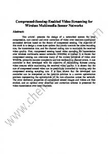
has no effect on others vertices. In a second mode, the effect is smoothened so that vertices adjacent to the selected ones are also affected by the motion, although with a lesser magnitude. That effect may be propagated further to their neighbors and so on, with less and less magnitude. Attachment: Specified adjustments of texture coordinates will be applied to the currently selected vertices. Their effect will be propagated to the neighboring vertices. Image: A refinement of the mapped image is used, as represented in JPEG-2000 progressive image coding. In the proposed system, the 3-D model will be first decompressed to get a crude 3-D mesh, a rigid body motion, a set of crude images to be used as textures, and a coarse specification of how these textures are to be mapped upon the surface. If no chunk follows, the animation will be a rigid body motion of a fixed shape with a fixed texture. Otherwise, it will decompress the refinement chunks as they arrive and execute them to alter the mesh, the texture, or the motion. Note that chunks may be associated with time intervals that do not span the whole time interval between the current frame and the next one. The decompression will thus keep track of the activation and expiration time of each chunk. For example, a chunk could start midway between the current and the next frame and last only a short amount of time during which the selected vertices will be moved slightly to create a bump. The bump formation will be gradual during the time interval associated with the chunk. The bump will remain static afterwards. The effect of various chunks may be combined. For example, some vertices may be subject to the combined motions of two chunks. These will be executed one after the other and their effects cumulate, as in the scene graphs of popular graphics APIs. To estimate the distortion at the decoded mesh, we used the Hausdorff distance to measure the maximum distance between the overlysampled transmitted and decoded meshes. The importance of chunks and their bit-sizes are established by the compression process, which must make certain decisions: (i) which vertices to refine, deform, move or use to attach a texture to, (ii) how many bits should be used to represent the associated parameters, and (iii) how to compress this information. These three decisions are intertwined. For example, for meshes that are compressed progressively, there are two methods of reducing the source coding rate: reducing geometry precision, i.e., the number of bits used to encode each coordinate, or reducing the number of transmitted triangles. Although both operations control the size of the transmitted bitstream, they affect the decoded mesh quality in different ways. In [3], the number of transmitted triangles is kept the same and the number of source coding bits is reduced by using coarser quantizers. In this paper, we choose the optimal combination of the number of transmitted triangles and the quantizer step size as will be explained in Section 4. In order to measure the effect of each of these two size-reduction methods on the decoded mesh quality, we fixed the number of encoded levels (called batches hereafter) and used a spectrum of quantizers to encode the mesh. In each case, we decode all batches and calculate the Hausdorff distance between the overly-sampled transmitted and decoded meshes. The resulting curve from these calculations is a set of rate-distortion (R-D) curves that estimate the distortion at the decoded mesh as a function of the number of received bits. Figure 1 depicts the R-D curves for the TRICER ATOPS model when l-bit quantizers (where l ∈ {8, 4, 2}) were
used and the number of batches (M ) is fixed to 10.
Figure 1: R-D curves for the TRICERATOPS model that is compressed into 10 batches using: 8, 4, and 2-bit quantizers. These R-D curves and similar ones for other meshes reflect two major facts. First, for a given bit-budget, the best encoded bitstream is the coarsest-quantized one for a certain range of quantizer precision. In other words, using a coarser quantizer allows us to add more triangles than a finer quantizer for the same bit-budget and hence tessellation is more important than coordinates precision. This is true for a certain range of quantizers because when a very coarse quantizer is used, tessellation will not improve the mesh quality. Thus, a second major conclusion from these R-D curves is that there exists a minimum quantization precision to be used to quantize geometry. These conclusions coincide with the results reported in [9] for single-level compressed 3-D meshes. Because of packet losses and time-sensitivity of 3-D animation applications, we propose to protect transmitted chunks using forward error correction (FEC) codes. The importance of each chunk differs from one category to another, and hence, we distribute error-protection bits unequally among transmitted chunks and unequally among the layers within each class of chunks. The framework of assigning importance measure as well as error-protection bits to these chunks is discussed in the following section. 3. ERROR RESILIENT TRANSMISSION Our proposed error-resilient transmission method is best explained via an example. Consider three chunks, X, Y , and Z. Let QX , QY , and QZ , denote respectively the improvement in the animation quality resulting from applying the refinements described in these three chunks (Q stands for quality). Assume for simplicity that these chunks are of different type. For example, X is a selector, Y is a motion, and Z is an attachment. Assume that both Y and Z will be applied to the vertices selected by X. Thus, the benefit of Y and Z may be considered independent of each other, but they both depend on X. If X is lost, then neither Y nor Z can be executed. Hence, their benefits are conditional to X. On the other hand, if X is received and Y is lost, Z can still be executed. Although in some cases, refining a texture attachment may have less benefit if the vertices are not properly positioned, we will consider that the benefit of Z is independent on whether Y was received or not. Here QX = 0, because executing X alone has no benefit. But the probabilities p(Y ) and p(Z) of receiving Y and Z must be multiplied with the probability p(X) of receiving X to obtain the probability of Y and Z being useful. Now, we want to optimally distribute our error-protection bitbudget on these three chunks. Error-protection bits allocated to
a given chunk increase its probability of being received and thus the probability of being able to apply the corresponding quality enhancement. Thus, we wish to maximize p(X)(p(Y )QY +p(Z)QZ ). Let SX , SY , and SZ , denote the bit-sizes of these three chunks and let CX , CY , and CZ , denote the corresponding number of channel error-protection bits. Thus, we wish to select CX , CY , and CZ so as to minimize p(X)(p(Y )QY + p(Z)QZ ) given both the channel bandwidth and the channel error characteristics. Channel characteristics are encapsulated in p(X), p(Y ), and p(Z). These statistical expressions depend on the channel model we use as well as the packetization method we implement. We will use the Gilbert-Elliot model to simulate the channel packet loss behavior and the block of packets structure to packetize the packets for transmission [3]. In the above formulation, compression decides on the chunks and the layers within each class of chunks. This is done independently of channel coding. Then, the server will decide on what chunks to send, the number of error-protection bits to be assigned to every chunk (a joint source and channel coding problem), and the distribution of these error-protection bits among the layers within each class of the transmitted chunks (an unequal error protection problem). All these parameters are determined optimally for a given channel and pre-determined bit-budget. Of course we usually have more than three choices and the dependencies between them may be more complicated than those given in the above example. 4. JOINT SOURCE AND CHANNEL CODING OF 3-D KEY-FRAMES We applied the above error-resilient transmission system to a specific example of sending connectivity and accuracy chunks for a subset of vertices selected by the CPM (compressed progressive mesh) [8] algorithm. CPM produces a set of batches that refine the crudest model. Each batch specifies how to split certain vertices to refine the model connectivity or it specifies a number of bits to refine the coordinate of some of the already received vertices. We determine the number of source coding bits, the number of channel coding bits and the distribution of the channel coding bits among transmitted layers numerically. First, a source coding bitbudget is chosen and the compression algorithm determines the optimal vertex/quantization ratio and makes chunks, compresses them, sorts them and labels them with bit-size and with benefit (quality enhancement). This is all done for a given source coding bit-budget. Then, the bit allocation algorithm distributes the channel coding bits among the transmitted layers and chooses the distribution that maximizes the decoded mesh quality. After that, another source coding bit-budget is assigned and the whole process is repeated. This process is repeated according to the desired accuracy level of the numerical solution. Finally, from all these numerical solutions and the corresponding source and channel coding bit-budgets, the best combination of quantization, connectivity and channel coding bits distribution is chosen as the optimal solution and the bit stream is transmitted accordingly. In this paper, we determine the best combination of accuracy and vertex quantizers for a given source coding bit-budget experimentally using R-D curves similar to the ones shown in Figure 1. In summary, given a 3-D model and a source coding bit-budget, we need to determine the minimum quantizer after which tessellation does not improve the mesh quality, determine all encoded bitstreams that can meet the given bit-budget, and choose the coarsest
quantized bit-stream among these as the optimum bit-stream. We solved the above optimization problem numerically for a set of 3-D models. We used the G-E model as the channel model and the block of packets structure as the packetization scheme. The reader is referred to [3] for more details. For example, we compressed the TRICERATOPS model progressively using the CPM algorithm into 10 batches. Also, we set the average burst length, LB , to 5 and the FEC (Reed-Solomon codes are used in this paper) packet size is set to 100. Figure 2(a) depicts the maximum error between the transmitted and the decoded meshes as a function of the packet loss rate (PLR ) for the TRICERATOPS model. Three curves are shown for the unequal error protection (UEP), equal error protection (EEP) and no error protection (NEP) methods. The total bit-budget is chosen to be 70, 000 bits. As can be seen from these curves, when the channel is error-free, all three methods experience the same distortion, which results primarily from quantization. However, when the packet loss rate increases, the proposed UEP method shows a more graceful degradation compared to the other two methods. An important observation from these curves is that after a packet loss rate of 20%, the experienced degradation for any method does not change considerably. This is because at such high packet loss rates a major part of the connectivity as well as geometry is lost and hence the decoded mesh is considerably distorted.
results as well as the corresponding subjective results show that the proposed UEP and the optimal1 joint source and channel coding methods kept a considerable quality level of the decoded 3-D key-frame compared to both EEP and NEP. 5. CONCLUSIONS In this paper, we presented a protocol for an efficient error-resilient streaming of 3-D animations over lossy channels. We set up an optimization problem whose solution determines the optimal number of bits assigned to each transmitted animation data (called chunks in this paper) as well as the number of corresponding channel coding bits for each chunk. We jointly design source and channel coding to maximize the animation played on the client’s side. We solved the system for a specific enhancement layer where geometry and connectivity information is refined without sending any deformation, motion or texture data. Currently, the authors are working on solving the complete problem by first solving the optimization problem when deformation, motion or texture data is sent to enhance the animation. Then, all six enhancement layers will be combined for an optimal bit-budget allocation algorithm. 6. REFERENCES [1] J. Rossignac, “3-D compression,” in Lecture at the ACM SIGGRAPH’99, 1999. [2] Ghassan Al-Regib and Yucel Altunbasak, “An unequal error protection method for packet loss resilient 3-D mesh transmission,” in Proceedings of IEEE INFOCOM, New York, NY, June 2002.
(a) Total bit-budget is 70, 000 bits.
[3] Ghassan Al-Regib, Yucel Altunbasak, and Jarek Rossignac, “An unequal error protection method for progressively compressed 3-D meshes,” in The Proceedings of the IEEE ICASSP’02 (Accepted for Publication), Orlando, FL, May 2002. [4] S. Varakliotis, J. Ostermann, and V. Hardman, “Coding of animated 3-D wireframe models for internet streaming applications,” in International Conference on Multimedia and Expo 2001, 2001, pp. 353–356. [5] Z. Yan, S. Kumar, and C.-C. J. Kuo, “Error resilient coding of 3-D graphic models via adaptive mesh segmentation,” IEEE transactions on circuits and systems for video technology, vol. 11, no. 7, July 2001.
(b) Total bit-budget is 50, 000 bits. Figure 2: Simulation Results when UEP, EEP and NEP methods are applied on the TRICERATOPS mesh for two total bit-budgets. (LB =5.0) The same experiments are repeated when the total bit-budget is 50, 000 bits and the results are depicted in Figure 2(b). These curves differ from he corresponding ones in Figure 2(a) when PLR ≤ 15% where the latter outperforms the former since more bits are available for both source and channel coding. When PLR > 15%, both plots show the same degradation in the decoded mesh quality since the mesh is already subject to high packet loss rate. These
[6] J. Signes, Y. Fischer, and A. Eleftheriadis, “MPEG-4’s Binary Format for Scene Description,” Signal Processing: Image Communications, vol. 15, no. 4-5, 2000. [7] H. Hoppe, “Progressive meshes,” in Proceedings ACM SIGGRAPH’96, 1996, pp. 99–108. [8] R. Pajarola and J. Rossignac, “Compressed progressive meshes,” IEEE Transactions on Visualization and Computer Graphics, vol. 6, no. 1, pp. 79–93, January-March 2000. [9] D. King and J. Rossignac, “Optimal bit allocation in compressed 3D models,” Journal of Computational Geometry, Theory and Applications, vol. 14, no. 1-3, pp. 91–118, November 1999.
1 Optimal
in the Hausdorff distance sense.