Indian Journal of Science and Technology, Vol 9(46), DOI: 10.17485/ijst/2016/v9i46/106909, December 2016
ISSN (Print) : 0974-6846 ISSN (Online) : 0974-5645
Prototype Development to Detect Electric Theft using PIC18F452 Microcontroller Saad Bin Yousuf1, Mohsin Jamil1,2, M. Zia ur Rehman1, Asif Hassan1 and Syed Omer Gilani Syed1 Department of Robotics and Artificial Intelligence, School of Mechanical & Manufacturing Engineering (SMME), National University of Science and Technology (NUST), Rawalpindi, Pakistan;
[email protected],
[email protected],
[email protected],
[email protected],
[email protected] 2 Department of Electrical Engineering, Faculty of Engineering, Islamic University Madinah, Kingdom of Saudi Arabia;
[email protected]
1
Abstract This paper presents the development of a prototype to detect electric theft using PIC18F452. The proposed prototype is robust, adaptable, repairable and easy installable. It monitors the flow of charge from the phase line i.e. supply line, the neutral line and constantly compares them. Moreover, it shows real time flow of charge in the both phase line and the neutral line. It also represents the real time voltage and the power being supplied to the load. It is also fitted with an alarm system that sounds an alarm when there is any electric theft. The prototype was able to adapt to different kinds of attenuating voltages between 200-240 volts. It was tested at different loads and findings were inconsistent with the theoretical ones. What makes this device unique is that it can be fitted anywhere in any electrical system. It can be used as metering device. It can also be used as a smart grid surveillance device when used in collaboration with multiple devices of same or different kind.
Keywords: DSP, Electric Theft, MATLAB, Meter, PIC18F452, Prototype
1. Introduction Electricity theft is a major problem in any electrical system1–6. It is a major reason for the decline of the quality of life. There exist many cases of immense amount of power theft in industrial sectors in the world which caused the loss to the power companies in millions of dollars. Electrical energy theft is common in many countries and a substantial quantity is stolen annually from electricity grids. It degrades the economic condition of utilities, cuts back new investments for electrical capacity development that finally leads to electricity shortage. In Pakistan it is reported that all the electric supply companies together lost a total of 90 billion Rupees on account of theft and line losses. The total mounts to 90 billion in a Year1.
*Author for correspondence
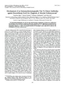
Electricity theft is not only a major reason for load shedding, while the financial loss happening from stealing of electrical energy also does not allow electricity companies to improve their distribution system of electricity. What thieves usually do in their homes is that they hook a wire to the main phase wire before the meter or they connect the load from one phase wire from the electricity pole and the other neutral wire they take from the meter or it is the other way round2. Electric theft has become such a big problem in our country. Our government has opted for many different plans to prevent electric theft but mostly these strategies were non-technical in nature. These plans included making legislature and defining hard punishments for thieves3. The block diagram of proposed model is shown in Figure 1.
Prototype Development to Detect Electric Theft using PIC18F452 Microcontroller
Figure 1. Block diagram of system.
The basic principle for theft detection in this device is current sensing. Current sensing is used to perform essential circuit functions. In our case we will use it to measure “how much” current is flowing in a circuit, and then make decisions on it6. The main difficulty while designing this device was which type of electronic component to use to sense the currents flowing in the wires. There were number of options such as Hall Effect Integrated Circuit (IC’s) such as ACS712 or to use current sensing relays. Basically it came down to the two methods direct or indirect calculation of current in a wire. The direct method used current sensing resistors, Inductor Direct Current (DC) resistors (using Ohm’s law to calculate I=V/R).The second method was the indirect method, in this method the current transformer, Rogowski Coil, RDS on and Hall Effect devices are used5. There have been other proposals by different individuals proposing technical solutions such as smart meters and using wireless billing techniques.4 We used the current transformer due to its availability and reliability.
2. Prototype Architecture We divided the Prototype into five sections on the basis of design and principle. 1. 2. 3. 4. 5.
The signal conditioning section The power section The theft indication section The PIC 18F452 The coding section
2.1. Signal Conditioning The voltage signal is stepped down using a 220-12v transformer. Now a voltage divider circuit is used to further step it down to approximately to 1volt Rms peak. Then a coupling capacitor is used to separate the resistors and
2
Vol 9 (46) | December 2016 | www.indjst.org
then a potentiometer is used to give the DC shift to the signal. The DC shift is given so that the negative and the positive peaks fall in the range of the PIC microcontroller (i-e 0-5 volts). Then a buffer circuit is used. This circuit is used so that two kilo Ohm pull up resistor that is used with the microcontroller does not combine with the potentiometer at the back end and form a voltage divider circuit thus disrupting the circuit. A DC shift of 2.5 volt is given by adjusting the potentiometer
2.2. Power Section Firstly I used an adapter to convert 220v to 12volt dc and one ampere current. And in this section I used a simple regulator LM 7805 to convert to 12 volt to 5 volt dc. I additionally used a Light Emitting Diode (LED) to indicate whether the circuit is receiving the power or not. This section is necessary to give the microcontroller the power and also to power all the integrated circuits.
2.3. Theft Detection The main purpose of this section is to sound the alarm. A simple Field Effect Transistor (FET) is used in this section as trigger mechanism. The signal from the microcontroller acts as a trigger which sounds the alarm through the FET.
2.4. The PIC 18F452 The PIC 18F452 is the heart of the project all the coding done is C language is in the controller. My reasons for choosing PIC 18F452 were its unique capabilities of low voltage detection and digital signal processing. We used MPLAB software and PIC2 programmer to burn the coding on to the Microcontroller.
3. Working Principle The main principle on which the device works is to read the current value and the voltage value at 220V 50 Hz and then step it down to the level of the PIC microcontroller and detect theft by comparing the forward current (main phase line) and the reverse current. (Neutral line). This device can be mounted before the meter. It will have to be installed permanently before every meter. We can also modify it so that it can be used as movable electricity theft detection unit. There are various different applications for this type of prototype. First of all it can be used as a theft
Indian Journal of Science and Technology
Saad Bin Yousuf, Mohsin Jamil, M. Zia ur Rehman, Asif Hassan and Syed Omer Gilani Syed
detection meter. Then this meter can also be used to find the power consumed by the load and also this meter can be used in the industry to manage their loads and to control electricity usage at the peak hours, thus playing an instrumental role in managing unit consumption in the industry. This project can also be used for telemetry applications. It can also be used in industrial control system and also it can be used in SCADA (Supervisory Control and Data Acquisition System).
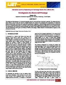
5.1. Case1: No Theft Condition The Figure 3, Figure 4 and Figure 5 shows the results when no energy theft was taking place. The Phase line and Neutral Line currents are shown.
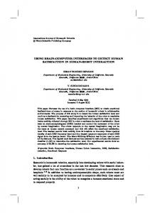
4. Flow Chart and Code Description Figure 2 shows the simplest flow chart. The proposed
hardware compares the forward and reverse currents. If these are not equal, then alarm is ON which is indication of energy theft. All calculations were done in RMS values. The used code is given in appendix.
Figure 3. Real-time current Signals (phase line current and neutral line current).
Figure 4. Real-time current values are shown on the LCD (when no theft occurs).
Figure 2. Flow chart explaining logic.
5. Simulation and Results The simulations were carried out using Proteus software. The actual hardware was tested under no theft (Case1) and theft conditions (Case 2).
Vol 9 (46) | December 2016 | www.indjst.org
Figure 5. Simulation on proteus software (real time values can easily be compared to simulated values).
Indian Journal of Science and Technology
3
Prototype Development to Detect Electric Theft using PIC18F452 Microcontroller
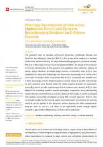
5.2. Case 2: At Theft Condition The Figure 6, Figure 7 and Figure 8 show the results
when energy theft was taking place. Now when theft occurs the code in PIC microcontroller detects it and sounds the alarm and displays it on the LCD. The oscilloscope shows the difference of the current in the two wires.
6. Conclusion The simplest and economical prototype was developed and tested for energy theft applications. The results were satisfactory.The most challenging part of the project was current sensing part. We had decided that we would use the Hall Effect IC to detect theft but due to the attenuating supply and undependable power source and also due to the undesirable results we had to switch over to current sensing part through the current transformers. Then came the coding part the loop that converted the signal to digital domain was a challenge itself. The time period for one complete wave was 20ms (1/50Hz). Also the frequency fluctuated. The system will be further developed for commercialization with the support of local industry.
7. Future Recommendations
Figure 6. Real-time current signals (phase line current and neutral line current) are shown on the oscilloscope (when theft occurs)
In future, a GSM module can be added to message a main data center of any theft involved. A data Centre can be made to monitor all meters at all times. A remote switch can be added to remotely shut down the meter connection where the theft took place. This device is just a prototype. To make it a marketable project there are many different specifications will have to be added. The improvements that can be made are as follows: 1. A GSM module can be added to message a main data center of any theft. 2. A data center can be made to monitor all meters real time. 3. Theft can be detected and swift action can be taken to apprehend thieves. 4. A remote switch can be added to remotely shut down the meter connection.
8. References
Figure 7. Real-time current values are shown on the LCD (when theft occurs).
The LCD clearly shows the difference of the two currents and also shows the extra power being consumed at the Load.
4
Vol 9 (46) | December 2016 | www.indjst.org
1. Jamil M, Munir F, Khan AA, Mirza A. Telemetering and billing system for spatially distributed electrical power clients. Proceedings of the 8th International Multitopic Conference (INMIC); 2004 Dec. p. 35–40. 2. Jamil M, Hashmi GM. Design and development of wireless energy metering for automatic billing in power sectors. 13th IEEE/IFAC Conference on Methods and Models in Automation and Robotics (MMAR); 2007 Aug 27–30; Poland.
Indian Journal of Science and Technology
Saad Bin Yousuf, Mohsin Jamil, M. Zia ur Rehman, Asif Hassan and Syed Omer Gilani Syed 3. Patil S, Pawaskar G, Patil K. Electric power theft detection and wireless meter reading. International Journal of Innovative Research in Science, Engineering and Technology. 2013 Apr; 2(2). 4. Depuru SS. Modeling, detection and protection of electricity theft for enhanced performance and security of grid [PhD thesis]. USA, The University of Toledo; 2012 Aug. 5. Sahoo S, Nikovski D, Muso T, Tsuru K. Electricity theft detection using smart meter data. Proceedings of IEEE Power and Energy Society Conference on the Innovative Smart Grid Technologies (ISGT); 2015 Feb 18–20; USA.
6. Jokar P, Aranpoo N, Leung VCM. Electricity theft detection in AMI using customer’s consumption patterns. IEEE Transaction on Smart Gird. 2016 Jan; 7(1): 216–26.
clc;clear all; close all fs=512; amp=sqrt(2); t=[0:pi/128:2*pi]; y=amp*sin(t); %Vp-p 1.41 (1 V RMS) and 256 samples subplot (2,1,1); stem(t,y); ySquared=y.^2; subplot (2,1,2); stem(t,ySquared); MeanSquared=sum(ySquared)/(length(ySquared)-1); rms=sqrt(MeanSquared); disp(‘RMS Value :’); disp(rms);
9. Appendix The following Matlab Code was used to implement on DSP/ Microcontroller.
Vol 9 (46) | December 2016 | www.indjst.org
Indian Journal of Science and Technology
5