Prototypical Implementation of Location-Aware Services based on a Middleware Architecture for Super-Distributed RFID Tag Infrastructures ∗ J¨ urgen Bohn Institute for Pervasive Computing ETH Zurich, Switzerland
[email protected] Summary. We provide evidence of the feasibility and effectiveness of a middleware architecture for mobile devices which employs dense distributions of small computerized entities for providing fault-tolerant location-aware services. We do so by describing exemplary implementations based on radio frequency identification (RFID) as an enabling technology. Firstly, we present prototypical implementations of the hardware abstraction layer and of selected core middleware services. The latter enable a mobile device to store and retrieve data and position information in physical places in a fault-tolerant manner, and to identify places based on a location abstraction which is robust against failure of individual tags. Secondly, we investigate the feasibility of some higher-level services and applications by developing and evaluating prototypical systems for tracing and tracking, self-positioning, and collaborative map-making. Keywords: ubiquitous computing; location awareness; super-distributed RFID tag infrastructures; radio frequency identification; positioning; map-making.
1 Introduction Different from conventional means of RFID tag deployment and utilization, massively-redundant tag distributions provide novel RFID-based services and applications to mobile user devices [2]. By deploying cheap passive RFID tags (i.e., tags without a built-in power supply) in large quantities and in a highly redundant fashion over large areas or object surfaces, one obtains a so-called super-distributed RFID tag infrastructure (SDRI). Based on such an SDRI, [2] identifies a number of technical challenges and describes potential ∗
An earlier version of this article [1] was presented at the 19th International Conference on Architecture of Computing Systems (ARCS ’06) in Frankfurt am Main, Germany.
2
J. Bohn
benefits and first prototypical results. The practical relevance of this concept is reflected in the recent appearance of industrial products that make use of such redundant RFID tag distributions, such as the “first carpet containing integrated RFID technology” presented by Vorwerk in cooperation with Infineon Technologies [3]. As a generalization of the SDRI concept, we propose super-distribution of small computerized (and therefore “smart”) entities as a general design principle for the development of reliable and highly available location-dependent services for mobile devices. For that, we developed a layered service middleware architecture [4] that exploits two fundamental characteristics of the resulting infrastructure for achieving fault-tolerance and serviceability: the high degree of redundancy with regard to smart entities (abundance aspect), and the support for localized interaction between mobile devices and their immediate physical environment (locality aspect). In this paper we describe a number of concrete prototypical implementations based on super-distributed smart entities, using RFID as an enabling technology. In doing so, our major aim is to provide first-hand evidence of the practicability and effectiveness of the suggested approach by demonstrating the capabilities and performance of exemplary middleware service implementations, rather than presenting specific state-of-the-art solutions for the particular application domains we cover in the process. In the following, we define a smart entity (SE) as a physical artifact that is enhanced by embedded computing technology in such a way that it has a globally unique identifier, a built-in memory with data read/write capabilities, and support for close-range wireless ad-hoc communication. Likewise, we refer to super-distribution of smart entities as the process of deploying and distributing SEs in a dense, highly redundant fashion. The resulting substrate is called a super-distributed smart-entity infrastructure.
2 Middleware Support for Super-Distributed Smart Entity Infrastructures 2.1 Middleware Architecture Our service middleware for super-distributed SE infrastructures described in [4] is based on a five-layered architecture (Fig. 1): The distributed physical smart entities in their entirety constitute the physical infrastructure on the lowest level (Hardware Layer or Layer 0). The access to this layer is controlled by the Hardware Abstraction Layer on the next higher level (Layer 1). It is represented by an Entity Read/Write (ERW) service, which defines a generic and unifying interface to the underlying physical SE infrastructure. The Core Service Layer (Layer 2) consists of fundamental abstractions and generic services that operate with individual SEs by means of the ERW service. The Higher-Level Service Layer (Layer 3) is represented by a collection
2 Middleware Support for Super-Distributed Smart Entity Infrastructures
3
of specialized services and service templates. These services do not directly operate on individual SEs of the underlying physical infrastructure but rely on the core services instead. Finally, in the Application Service Layer (Layer 4), we find application-specific services and specialized instantiations of service templates. Sensor-Assisted Sensor-Assisted Pos. Pos.Reckoning Reckoning
Collaborative Collaborative Map-Making Map-Making
Specialized Specialized Sensor-assisted Sensor-assisted Tracing Tracing&&Track. Track.
Specialized Specialized Entity-based Entity-based Tracing Tracing&&Track. Track.
Specialized Specialized Directory Directory Type TypeXX
Specialized Specialized Directory Directory Type TypeYY
Layer 4: Application Service Layer Device DevicePresence Presence Manager Manager
Advanced AdvancedMap Map Manager Manager
Generic GenericTracing Tracing&& Tracking TrackingService Service
Topology Topology Manager Manager
Generic GenericDirectory Directory Service Service
Layer 3: Higher-Level Service Layer Local Local Data DataSharing Sharing
Position Position Manager Manager
Location Location Manager Manager
Region Region Manager Manager
MoD MoDPosition Position Reckoning Reckoning
Basic BasicMap Map Manager Manager
History History Manager Manager
Layer 2: Core Service Layer Entity EntityRead/Write Read/Write Layer 1: Hardware Abstraction Layer
Layer 0: Physical Smart Entity Infrastructure Layer (Hardware Layer)
Fig. 1. Overview of the service middleware for super-distributed smart entities
The middleware architecture is extensible, facilitating the integration of additional services by means of a modular design. For dependable operation, the redundancy resulting from the super-distribution of SEs is exploited by the middleware services for the realization of fault-tolerance mechanisms. Service bootstrapping and maintenance tasks are performed autonomously by the individual services, as far as possible, thus reducing the need for manual intervention and servicing. For instance, the core middleware services support the integration of additional SEs that are distributed at a later point in time without a noticeable service interruption (hot-integration of SEs) [4]. Further, the services of the lower middleware layers mask the complexities of applied fault-tolerance, self-organization, and self-calibration mechanisms as well as hardware-specific details from higher-level services and applications. 2.2 Middleware Employment From the user’s perspective, interaction with the SE infrastructure is performed by means of a mobile device (MoD), which features a wireless communication interface for communicating in an ad-hoc fashion with SEs in its immediate vicinity. On each MoD, an independent instance of the service middleware is installed, executing the individual middleware services as separate
4
J. Bohn
processes (modules). Services can be turned on or off and configured separately, which allows the MoD to adjust the computational load according to the available resources and the currently required functionality. A MoD can be carried by a user or may be part of other devices, such as being integrated into a vehicle, a wheelchair, or into a blind man’s stick, for example. The execution of the service middleware on the MoDs themselves (rather than providing the services as part of a fixed background infrastructure) empowers the devices to interact with the super-distributed smart-entity infrastructure in an autonomous fashion. In particular, by maintaining information in SEs at the physical places where it is required, middleware services on a MoD can remain operational even in the case of physical damage in other areas of the infrastructure, and in the absence of network connectivity or the unavailability of remote services. Note that – in contrast to sensor networks – our work is concerned with the explicit goal of enabling individual MoDs (or their users) to directly and locally interact with – possibly passive – SEs placed in the physical environment. Communication between the SEs themselves is much less an issue than in sensor networks. 2.3 Prototypical Reference Implementations based on RFID For our prototypical implementation, we selected a number of exemplary middleware services based on both a bottom up and top down approach: On the one hand, we implemented services of the lower layers that provide general basic functionality, which includes the Hardware Layer, the Hardware Abstraction Layer, and three essential services of the Core Services Layer: Local Data Sharing, Location Manager, and Position Manager. On the other hand, based on these services, we investigated the feasibility and practicability of some higher-level services by developing and evaluating prototypical systems for tracing and tracking, self-positioning, and collaborative map-making. In our implementations, the SEs were represented by passive RFID tags. As a result, the Hardware Layer in our prototype implementation constituted a super-distributed RFID tag infrastructure (SDRI) as described in [2]. We therefore use the terms “RFID tag” or simply “tag” synonymously with “smart entity” in the remainder of the article. The MoD executing the service middleware software was represented by a notebook computer, to which a mobile RFID reader and antenna were attached to enable a localized interaction with the SDRI. 2.4 Motivating Scenarios In the following, we first present scenarios that highlight various opportunities and advantages of services based on a super-distributed SE infrastructure from the perspective of the user. We then motivate the need for middleware support from the systems developer’s point of view.
2 Middleware Support for Super-Distributed Smart Entity Infrastructures
5
User-Centric Location-Dependent Services Within a super-distributed SE infrastructure, users directly interact with the SEs at their current location. This enables applications for geographic guidance and navigation, where a MoD determines its current position by calculating an estimate from the individual positions stored on nearby SEs, or simply looks up the current location with the help of a local map containing the positions of individual SEs. A super-distributed SE infrastructure can also be employed in the sense of a “ubiquitous blackboard”, where users share information about local points of interest or leave personal messages directly in the physical places where the information is most helpful and required. For instance, it is conceivable to provide public directories whose entries are physically distributed across SE infrastructure, providing localized information about room numbers or names of departments, offices, or personnel, enabling visitors to find their way unassistedly even in unfamiliar places and buildings with the help of their MoD. Besides, users can leave virtual data traces in an ad-hoc fashion on the SEs passed along the way, similar to “pheromone trails” laid by ants, permitting friends or colleagues to follow at a later point in time to places where an activity or meeting is to take place. By integrating the MoD with a blind man’s stick or with a wheelchair, visually impaired people or persons with walking disabilities can be empowered to make use of these services, too, thus greatly enhancing their capabilities of perceiving and interacting with their physical surroundings. Such users particularly benefit from the ability to share information in situ that is tailored to their particular needs, such as information about nearby obstacles, dangerous crossings, handicapped accessible ramps and gangways, etc. Dependable and Safety-Critical Services Disasters caused by natural or human factors (e.g., earthquakes, large fire incidents, or terrorist attacks) often lead to the failure of infrastructure services in buildings or public places, disrupting electricity and communication networks. However, by maintaining safety-critical information in SEs at the physical places where it is required by rescuers, services based on super-distributed SE infrastructures remain operational in physically intact areas of the SE infrastructure even when conventional background service infrastructures collapse or other areas are damaged, as the MoD directly interacts with local SEs via short-range ad-hoc communication. In addition, a super-distributed SE infrastructure allows for the provisioning of dedicated emergency services. For instance, by means of permanent virtual data traces stored on the SEs of a super-distributed SE infrastructure, it is possible to provide services that direct users (including professionals such as firefighters and emergency physicians) to the nearest emergency exit or life saving equipment.
6
J. Bohn
Systems Support for Collaborative Activities In some cases the activities of individual MoDs can be combined to contribute to a global task. For instance, MoDs that have a third-party positioning service (such as GPS) at their disposal can store obtained position readings on the SEs at their respective places. Thus the SE infrastructure can be “bootstrapped” with position information over time through a collaborative effort. Another example for collaboration is the construction of a global site map of a superdistributed SE infrastructure by joining partial SE mappings obtained from individual MoDs, as we later see in Sect. 5. An SE infrastructure can also serve as a vast communal information space: the individual contributions of users in different physical places can contribute to the creation of open, communitydriven information services and directories. Middleware Support While in general the ad-hoc realization of specialized applications and services based on super-distributed SEs is always possible, such a procedure is bound to lead to closed systems with a narrow, limited scope and functionality. To support the systems developer in the rapid development of whole classes of applications, a fundamental challenge is to provide a set of general, basic services that satisfy a broad spectrum of requirements and needs. The development of reusable, basic services has the advantage that it greatly facilitates the development of higher-level services and applications. In order to identify location-dependent services that particularly benefit from the availability of a super-distributed SE infrastructure, we performed an analysis of the needs of various ubiquitous computing projects [5]. We further identified a number of basic building blocks that encapsulate the hardwarespecific aspects of the underlying physical infrastructure, provide low-level services and abstractions, and mask the complexities of fundamental maintenance and fault-tolerance management tasks from higher-level services. In a second step, we combined the various services into the layered middleware framework outlined earlier in Sect 2.1, according to their respective levels of specialization and universality. The detailed description of our general middleware architecture, however, is beyond the scope of this article and has been discussed elsewhere [4].
3 Implementation of Basic SDRI Middleware Services 3.1 Hardware Layer: Super-Distributed RFID Tag Infrastructure Prototype The RFID hardware we used for the SDRI consisted of ISO 15693 compliant smart labels (transponders) that operated at a frequency of 13.56 MHz. As
3 Implementation of Basic SDRI Middleware Services
7
transponders, we employed Philips I·CODE tags (Type 1) [6], with a dimension of 7.5 cm×4.5 cm×0.1 cm. The I·CODE RFID tags feature 64 byte of physical memory, which is organized into 16 slots ´a 4 byte (of which 11 slots are rewritable). This allowed us to store the data of several middleware services (e.g., Position Manager and Tracing and Tracking Service) directly on the physical memory of individual tags during our experiments. Table 1. Properties of plastic foil templates used for building a prototypical SDRI Dimension of plastic foil templates Mean distance between two adjacent RFID tags Standard deviation of tag distribution Number of tags per plastic foil template Average area covered by a single RFID tag Average RFID tag density per square meter
123 cm×128 cm 17.5 cm 2.1 cm 61 tags/foil 258 cm2 39 tags/m2
For building the SDRI, we attached the transponders onto four identical plastic foils using the same pseudo-random distribution pattern. This yielded four RFID-tagged templates with equal characteristics as shown in Table 1. 3.2 Hardware Abstraction Layer: Entity Read/Write For the realization of the Entity Read/Write (ERW) service on the Hardware Abstraction Layer, we used the RFIDStack [7], which offers a manufacturerindependent API to applications and incorporates drivers for various types of RFID hardware. Based on the RFIDStack, the ERW service provides the interface for writing data to and reading data from the underlying RFID tags of the SDRI, masking the complexity and hardware-specific characteristics of the underlying RFID hardware from the higher service layers. The writing of data can either be performed physically, writing to the physical tag memory, or virtually, storing the data in the so-called virtual tag memory. The latter is managed by a service instance of the RFIDStack residing in the Internet, which can be accessed by means of XML messages sent via a TCP connection [7]. The virtual tag memory not only mirrors the physical memory of a tag, but also provides an extended storage space. Our ERW implementation only allows a MoD to access the virtual memory of a tag if that entity is physically present within communication range. The ERW service also implements the data management for the physical and virtual tag memory. It emulates a simple file system for the physical tag memory, where Service Data Units represent files and the Smart Entity Directory represents the root directory. A Service Data Unit constitutes a servicespecific data unit that encapsulates the information that a service requires to be stored on a single tag for a well-defined purpose. To detect incomplete
8
J. Bohn
or inconsistent data units on tags caused by interrupted, incomplete write operations, CRC error checking is performed. In particular, the ERW service provides the following basic methods for accessing the physical memory of individual tags: listTags, listTagDirectory, writeTagFile, readTagFile, deleteTagFile. Parameters include tag ID, file type, file data, and flags that indicate the use of the virtual memory and declare if a file should be stored persistently or can be overwritten at a later point in time (persistence flag). 3.3 Core Service Layer: Local Data Sharing The Local Data Sharing (LDS) service provides MoDs with an API for sharing data in physical places of the SDRI with other devices. In doing so, the LDS service exploits the high tag density in the SDRI for fault-tolerant data storage by replicating Service Data Units across multiple tags in antenna range at the current location. Data can be shared in situ by using method shareData, which is parameterized with the service-specific data type and the persistence flag. Previously shared data can be retrieved by means of the getData method. The API of the LDS service allows the user to set the replication degree, which can be defined as an absolute number and which is targeted on a best effort basis, or as a relative percentage value. These values apply to the initial replication and the later replication maintenance procedure. The actual replication management is hidden from the service clients. For accessing the tags of the SDRI, the LDS service is based on the API of the ERW service. Further the LDS service allows to set a tolerance threshold for the number of failed tag identify/read/write attempts of the underlying ERW service. For example, if data is to be read from or written to eight different tags, failed read/write attempts for two of the tags are tolerated given a tolerance threshold of 25%. This enables the service to deal with known imperfections of RFID systems (e.g., tags in range may not be detected, or read/write operations may abort [8]). When Service Data Units are retrieved from local tags, the LDS service transparently filters duplicates. 3.4 Core Service Layer: Position Manager The main contributions of the Position Manager service are the methods getPosition and setPosition. The setPosition method enables a MoD to locally store its current position pM obtained from a third party positioning service on the nearby tags. In doing so, for each tag, the new position ptnew is calculated as the weighted mean of the position pM of the MoD and the old position ptold of the tag, using the number of previous write operations w as a weight: ptnew := (pM + w·ptold ) : (w + 1). Vice versa, upon calling getPosition, the Position Manager first scans all tags in antenna range and extracts their individual position coordinates if available. Then it calculates an estimate for the current position as the mean over all obtained individual tag positions.
4 SDRI Tracking and Positioning Prototype
9
3.5 Core Service Layer: Location Manager The Location Manager (LM) provides an API to define and resolve abstract locations: a Location has a unique identifier and is defined by the set of (stationary) SEs that are detected in a well-defined range of the MoD executing the service [4]. The Location identifiers are directly stored on the defining SEs themselves. The main contribution of the LM is the getLocation method, which determines an abstract Location L as the set of RFID tags tagIDSetl detected at the respective physical place l in the SDRI: L := tagIDSetl := {tagIDt : inRange(t, l, r)}, where tagIDt is the unique identifier of tag t, and inRange(t, l, r) a Boolean predicate that equals true iff tag t is within distance r of the field of the RFID antenna at place l and false otherwise. In our prototype system, the range r of the RFID system was defined by the characteristics of the used RFID hardware. Ideally, the range of the RFID reader/antenna should be customizable to enable the integration of different RFID systems with variable characteristics. If the getLocation method is called to determine the Location of the current place, then the LM searches for predefined Location identifiers on all tags in range r. The Location whose identifier is stored on the majority of the detected tags is returned as the current Location. In case no predefined Location is available, or if the number of tags containing the dominant Location identifier is below a well-defined percentage value T , then the LM automatically defines a new Location and stores the corresponding Location identifier on the affected tags. This ensures that adjacent Locations only overlap in up to (100−T )% of the tags, which in return enables a robust and selective Location detection in situations where individual tags fail to respond temporarily.
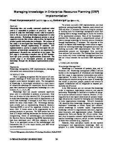
4 SDRI Tracking and Positioning Prototype The SDRI Tracking and Positioning prototype system provides two main services: laying and following of data traces, and self-positioning. 4.1 Prototype Description We have developed a fully functional SDRI Tracking and Positioning prototype, which consists of two major hardware components. Firstly, a trolley with the RFID equipment (RFID reader and antenna) and the MoD (in our case represented by a notebook computer running the SDRI Tracking and Positioning application). Secondly, four RFID-tagged templates forming a prototypical SDRI (Fig. 2). The RFID hardware consisted of an ISO 15693 compliant mid range RFID reader, and an external mid range RFID antenna2 . The RFID reader sup2
Manufacturer: Feig Electronic, model: OBID i-scan HF ISC.MR100 and OBID i-mid ISC.ANT340/240
10
J. Bohn
Notebook computer running tracking and positioning application
Trolley SDRI templates RFID reader device RFID antenna (not visible) Marked test track Fig. 2. Measurement trolley and prepared test track
ported collision resolution, which enabled it to simultaneously identify multiple transponders within antenna range. The RFID antenna was attached underneath the center of the bottom pane of the trolley, at 10 cm above the floor space. At this distance, the approximately square operating area of the RFID antenna was about 50 cm×50 cm. For constructing the prototypical SDRI, the four RFID-tagged templates described in Sect. 3.1 were arranged in an L-shape around a corner of a corridor in our office building (Fig. 2). On the templates, we manually marked a test track for our experiments with a total length of 526 cm. 4.2 SDRI Tracing and Tracking Service The SDRI Tracing and Tracking Service features a tracing mode, which enables the MoD to leave a digital data trace in the SDRI, and a tracking mode, which allows a MoD to follow a previously laid data trace. Each mode itself is divided into a basic and advanced version, which we describe in the following. Tracing Mode A basic trace is represented by a sequence of trace data objects stored on tags of the SDRI. Each trace data object (TDO) consists of an anonymous trace identifier (trace ID), which is generated by random, and a timestamp. A trace ID only has to be unique in the local area where it is applied, but not on a global scale. Further, all TDOs are flagged as non-persistent, and over time, the SDRI Tracing and Tracking Service overwrites the oldest TDOs on a tag with newer traces if memory space is short.
4 SDRI Tracking and Positioning Prototype
11
In our prototypical implementation, we replaced the timestamp in the TDO with a trace counter serving as logical clock to obtain a more compact, memory-space-saving representation. This was feasible since it is usually only necessary to locally distinguish the age of detected TDOs belonging to the same trace, which we achieve by applying a sliding-window approach. In addition, we adapted the TDO overwrite strategy to selecting a random TDO for replacement, as the use of logical clocks no longer allows to identify the oldest TDO on a tag. Memory-wise, we used 1 byte for the trace ID and one for the trace counter (with a window size of 12) per basic TDO, which fit into a single slot of our physical RFID tag memory. If tracing is active, new TDOs are stored in a redundant fashion on the RFID tags at the current position of the MoD (by using the Local Data Sharing service) at a well-defined update rate (specified in milliseconds). For preventing repetitive trace updates at the same physical location, which would lead to a discontinuity of the trace counter values, the IDs of the locally detected tags are cached. A new TDO is only written to the SDRI if at least K percent of the local tag IDs have changed. Concretely, we used a trace update rate of 500 ms and set the update tolerance to K = 50%. The advanced tracing mode uses position information (e.g., obtained from the Position Manager or from a third-party positioning service) to create an augmented trace: the individual trace data objects are augmented with the current information about direction (orientation), change of direction, and speed of the MoD. Tracking Mode The tracking mode of the SDRI Tracing and Tracking Service enables a MoD, the follower, to follow a trace by detecting the corresponding TDOs in the tags of the SDRI. We call the MoD that previously laid the trace the forerunner. Initially, the forerunner has to reveal its randomly chosen trace ID of the trace to the devices that are to become its followers, and to inform them about potential starting points for picking up the trace (which are not necessarily equal to the starting point of the trace). Once a follower has detected or rediscovered the trace (i.e., tags in the SDRI which contain a TDO with the forerunner’s trace ID), the follower repeatedly searches for tags with more recent trace information and moves into this direction. More precisely, the follower continuously seeks TDOs of the wanted trace ID with either a more recent timestamp, or with a higher trace counter value (based on the counter window calculated using modular arithmetic). In our system, the detected trace counter values for a specified trace are displayed in a graphical user interface window (GUI). If an RFID tag map of the prototypical SDRI is available, the GUI visualizes the tags of the trace that have been detected so far, and highlights the most recent trace information. In case of an augmented trace, the GUI also displays the
12
J. Bohn
augmented information, such as the current direction and change of direction (as numerical values and visually by means of an arrow symbol). 4.3 SDRI Positioning Service The SDRI Positioning Service enables the MoD to store position information to or to retrieve it from individual RFID tags of an SDRI, either using the physical on-tag memory or a remote virtual tag database. Calibration Mode For the calibration of the SDRI with position information, the SDRI Positioning Service supports two modes of operation: Firstly, the exact calibration mode allows the user to calculate the individual tag positions of all RFID tags of an SDRI template at once, based on two manually entered reference positions per template. The determined exact tag positions are then stored on the physical tags and/or in the virtual tag database. The physical tag calibration procedure is supported by a tool that shows the progress and status of the calibration with the help of a graphical display. Secondly, the incremental calibration of the SDRI uses the position information of a third-party positioning service to update the position coordinates on the individual tags by calculating a new weighted mean as described in Sect. 3.4. This procedure can be performed in a collaborative fashion by independent MoDs. In the process, the accuracy of individual tag position coordinates usually increases with the number of positions that are stored on the respective tags: as the actual positions of the MoDs performing the calibration are typically scattered around individual tags, the errors of the single position values that are averaged tend to cancel each other out. Positioning Mode The implemented position calculation or positioning procedure of the SDRI Positioning Service uses the positioning procedure of the Position Manager: First the tag position coordinates stored on the single RFID tags within antenna range are retrieved. Then the arithmetical mean of the obtained single tag position coordinates is calculated and used as the estimated position (x, y, z) of the MoD. 4.4 Experimental Results We performed our experiments by pushing the trolley at a constant speed along the marked test track (Fig. 2). We further calibrated the tags of the SDRI with local positioning coordinates using the exact calibration tool.
4 SDRI Tracking and Positioning Prototype
13
X [cm] 800
850
900
950
1000
1050
1100
1150
2600
2650
Y [cm]
2700
2750
2800
2850 Exact
Run 1
Run 2
Run 3
Fig. 3. Three positioning experiments of the SDRI Positioning Service performed at 50 cm/s
Efficiency of Virtual and Physical Tag Memory Access For our positioning measurements, we used both the virtual and physical tag memory. For accessing the virtual tag memory, which was maintained in a database on the MoD itself, it was sufficient for the ERW service to retrieve the IDs of all RFID tags within antenna range with a single command call (identify). The duration of the identify command was independent from the number of tags within range, and took approximately 200 ms on average (using 16 time-slots for multi-tag-detection as part of the anti-collision protocol of the reader). This enabled a maximum rate of up to 5 Hz for multi-tag detection and subsequent position calculation. The efficiency of the physical tag memory was more than one order of magnitude lower, since our particular RFID hardware required sequential scans for reading out a data slot: one identify command followed by a separate read command for each detected tag. In our implementation, we needed two physical memory slots to store positioning coordinates on a tag. Therefore, for attempting to read the two data slots from four RFID tags detected during an inquiry, the duration of the scan varied from approximately 2 seconds (8 successful reads), if no errors occurred, to up to 5 seconds (8 failed reads) in the worst case if all eight sequential read operations failed. These numbers are based on timing measurements for successful and failed attempts for reading a single data slot, which for our RFID hardware were approx. 250 ms and 600 ms respectively. However, if we used a more advanced RFID system that supported the direct and parallel reading of a data slot from multiple tags in range without a prior identify operation, the duration of the physical tag
14
J. Bohn
memory access would be reduced to the order of magnitude of the duration of the virtual tag memory access. Accuracy of the Positioning Procedure Due to the comparably slow physical tag memory access of our RFID hardware, we used the virtual tag memory for our experiments. We performed three test runs at a speed of 50 cm/s, using exact manual measurements of the test track as reference (Fig. 3). The resulting mean absolute positioning error was approx. 15 cm. Given our specific configuration, the maximum tolerable speed of the trolley is 2.5 m/s, which is determined by the tag inquiry time of approx. 200 ms (required by the ERW service for determining the tag IDs for accessing the virtual tag memory) and the length of the antenna field in moving direction of 50 cm.
5 Collaborative SDRI Mapping Prototype The prototypical Collaborative SDRI Mapping system has two main tasks: The localization and mapping of RFID tags in an SDRI by means of autonomous vehicles, and the merging of overlapping partial RFID tag mappings, which were constructed independently from each other by these vehicles as part of a collaborative effort. We do not aspire to contend with state-of-the-art solutions for the general collaborative map-making problem, which has been in the focus of research in the domain of mobile robots for decades (cf. to the work by Burgard, Fox, et al. [9, 10], for instance). Our primary goal is to demonstrate the feasibility and practicability of using a super-distributed RFID tag infrastructure for the realization of collaborative activities, which is not considered by traditional map-making systems. In contrast to our approach, RFID tags for positioning have so far only been used in the function of dedicated artificial landmarks on walls or floor spaces, providing auxiliary support to dedicated positioning and navigation systems [11–13]. 5.1 Prototype Description The Collaborative SDRI Mapping prototype consists of the following components: a model vehicle, a prototypical SDRI, an on-board vehicle control application (for evasive driving and dead reckoning), an off-board RFID tag mapping application, and a stand-alone collaborative map-merging application for fusing partial map observations obtained during independent test runs. The model vehicle was constructed using Lego Mindstorms [14] technology. It is self-propelled, featuring two actuated parallel wheels in the back (each
5 Collaborative SDRI Mapping Prototype
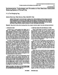
Fig. 4. Model vehicle with mu-chip reader on top of the Lego RCX, within the prototypical SDRI tagged with muchip RFID inlets
15
Fig. 5. Bottom view of the model vehicle prototype showing the wheel configuration, front bumper, and the mu-chip antenna
equipped with a rotation sensor and an electrically powered motor) and one castor wheel in the front for stabilization. A bumper sensor connected to a front bumper is used for collision detection. An on-board LEGO Mindstorms RCX controller hosts the software for controlling the motors of the vehicle, and for monitoring the rotation and bumper sensors. In addition, the model vehicle is equipped with an on-board RFID reader (Fig. 4), and an RFID antenna3 mounted at the bottom at 1 cm distance from the floor space (Fig. 5). Due to the size of the model vehicle, the vehicle control application was executed on a separate notebook computer, which was connected to the RCX controller and the RFID reader by cable. For obtaining a prototypical SDRI test area, we evenly distributed 32 muchip inlets across a wooden panel of the size of 50 cm×50 cm (Fig. 4). This corresponds to a tag density of 128 tags/m2 . Each mu-chip tag features a unique 128-bit ID stored in its read-only memory (ROM). The test area of was rounded off with a solid wooden barrier to mark off its boundaries. The on-board vehicle control application is executed on the RCX controller and performs the following actions: It triggers an evasion manoeuvre whenever the bumper sensor connected to the front bumpers reports an obstacle. It also continuously monitors the two rotation sensors and calculates the current position by means of a basic dead reckoning algorithm. The RFID tag mapping application is executed off-board on the notebook computer. It is connected to the RFID reader and continuously maps detected RFID tags, using the latest dead reckoning position information obtained from the RCX controller of the model vehicle as reference. Overlapping partial map observations, which were created during independent map making runs, are merged with a single, gradually growing compre3
Manufacturer: Hitachi Kokusai Electric Inc., model: MRE200 No. 1010 and PA12450AS
16
J. Bohn
hensive map of the area by the collaborative map-merging application. The map merging algorithm uses an affine coordinate transformation between two arbitrary maps with different local (or global) coordinate systems. The transformation is unambiguously defined by a translation vector and a rotation angle given two or more overlapping tags (i.e., tags that are contained in both maps). The affine transformation is calculated numerically using a least squares metric for minimizing the overall transformation error. 5.2 Experimental Results Experimental Method and Validation Four map-making test runs were carried out in our test area of 2500 cm2 . Starting from a random position (which served as the origin of the local coordinate system for the measurement), the model vehicle drove along a straight trajectory within the SDRI at a constant speed of 3.6 cm/s. Whenever the bumpers hit the encircling barriers, the vehicle stopped and performed an approx. 90-degrees turn on the spot, and resumed its straight movement. While driving, the off-board application recorded the tag IDs together with the corresponding local position coordinates of the tags detected by the RFID reader on the vehicle. The position coordinates were obtained from the dead reckoning program running on the vehicle’s RCX controller. Each test run lasted approx. 90 seconds, during which the vehicle performed 6 turns (each of which took approx. 6 seconds). Thus, on average, the vehicle covered a distance of approx. 200 cm per test run. To validate our experimental results, we have manually measured the exact local position coordinates of all RFID tags in the test area as a reference. To assess the quality of an experimental RFID tag map, we calculated the overall minimum, maximum, and mean absolute tag localization error. For an individual tag, the localization error was determined by calculating the Euclidean distance between its estimated position and its corresponding exact reference position. Dead Reckoning Error The driving distance of the model vehicle was approx. 0.33 cm per rotation sensor increment. The average absolute error of the dead reckoning algorithm for an approx. 90◦ turn of the vehicle on the spot was about 4%, and its lateral drift approx. ± 7 cm per meter during straight driving. When considering several consecutive turns, the occurring negative and positive errors partly annihilate each other, leading to a lower effective error. In our case, the overall error of six consecutive turns was reduced to approx. 1.4 %, which corresponds to an accumulated drift of only about 2 cm per meter of straight driving.
5 Collaborative SDRI Mapping Prototype
17
Tag Localization Error The specific RFID antenna we used detected tags inside an area of approximately 6 by 9 cm around its center point, at approx. 1 cm distance from the floor space. Since each mu-chip of our SDRI test area covered an area of approx. 78 cm2 , only one tag was within antenna range at a time. Therefore, whenever the model vehicle took its current reckoned position as a position estimate for a detected RFID tag, the error caused by the uncertainty about the exact tag position within the antenna tag reception area, which we call tag localization error, added to the dead reckoning error. In our prototype system, the tag localization error equaled the distance between the center of the tag reception area of the antenna and the center point of the mu-chip inlet. Concretely, assuming that the center point of the vehicle is also the center point of the RFID antenna tag reception area, the mean tag localization error amounted to approx. 2.7 cm. In the worst case, if a detected tag was situated in one of the corners of the tag reception area, the resulting maximum tag localization error was approx. 5.4 cm. Tag Mapping Error During the mapping, the deviation eT P of experimentally measured tag position coordinates from the true coordinates, which we call tag mapping error, is determined by two factors: the error eDR of the dead reckoning system (which is proportional to the distance traveled since the initial starting position was set), and the tag localization error eT L , which depends on the properties of the RFID hardware and RFID tag distribution: eT P = eDR + eT L . Evaluation of Mapping Procedure As a result of the four map-making test runs, four partial maps were created. In the process, on average 11 tags were detected per test run, and 21 different tags were detected altogether. Each two created maps overlapped in two or more tags. The resulting tag mapping errors for the tags of each partial map in comparison to the tags of the exact reference map are shown in Table 2. The average tag mapping error over four experiments was 4.1 cm, with little variation (standard deviation σ = 1.4 cm). The overall maximum tag mapping error remained below 8 cm. Evaluation of Map Merging Procedure To assess the robustness of our map merging procedure with regard to the order in which overlapping maps are merged, we have joined the four partial maps in different sequential orders and compared the resulting minimum, mean, and maximum tag mapping errors.
18
J. Bohn Table 2. Tag mapping errors of four experimentally constructed partial maps Partial map 1 2 3 4 Average:
No. of tags 10 9 11 14 11
Min. error Max. error Mean error 2.5 cm 6.7 cm 4.3 cm 1.0 cm 5.2 cm 3.2 cm 1.9 cm 7.3 cm 4.3 cm 2.0 cm 7.9 cm 4.4 cm 1.9 cm 6.8 cm 4.1 cm
Std. dev. of mean error 1.3 cm 1.3 cm 1.8 cm 1.3 cm 1.4 cm
Table 3. Tag mapping errors of pairwise merged partial maps Merged maps 1+2 1+3 1+4 2+3 2+4 3+4 Average:
No. of tags 15 15 21 17 16 18 17
Min. error Max. error Mean error 1.5 cm 8.1 cm 3.9 cm 1.4 cm 9.2 cm 5.2 cm 1.0 cm 10.0 cm 4.7 cm 1.0 cm 7.1 cm 4.0 cm 1.2 cm 7.9 cm 4.1 cm 1.3 cm 8.0 cm 4.2 cm 1.2 cm 8.4 cm 4.4 cm
Std. dev. of mean error 1.5 cm 2.5 cm 2.4 cm 1.8 cm 1.6 cm 1.9 cm 2.0 cm
In a first step, we merged the individual maps pairwise. The results show a slight increase of the mean tag mapping error to 4.4 cm, with a higher variability (σ = 2.0 cm), as shown in Table 3. The mean absolute tag mapping error increased slightly to 8.4 cm, with a new overall maximum error of 10.0 cm. The results differ significantly for each combined pair of partial maps. An explanation for this observation is that – at this stage – a better map merging result can be expected for maps that have more tags in common. Table 4. Tag mapping errors of maps obtained after two consecutive merging operations Merged maps No. of tags (1+2)+(3+4) 21 (1+3)+(2+4) 21 (1+4)+(2+3) 21 Average: 21
Min. error Max. error Mean error 0.5 cm 7.6 cm 3.8 cm 1.6 cm 7.6 cm 4.2 cm 0.8 cm 7.7 cm 3.9 cm 1.0 cm 7.6 cm 4.0 cm
Std. dev. of mean error 1.8 cm 1.6 cm 1.8 cm 1.7 cm
In a second step, we merged the previously paired maps. The resulting errors are shown in Table 4. We can see that the mean tag mapping error stabilized at 4.0 cm, with a lower standard deviation than in the case of the original partial maps. A stabilization can also be observed with respect to the
6 Conclusion
19
minimum and maximum errors. The maximum tag mapping error after two consecutive map merging operations has even dropped below the initial values to 7.7 cm. Apparently, independently from the merging order, the errors with opposite signs tend to partially cancel each other out as the estimated tag positions of all available partial maps are eventually combined.
6 Conclusion Based on an existing service middleware architecture for super-distributed smart entity infrastructures, we prototypically implemented basic middleware layers and services with the help of RFID technology: the Hardware Layer, the Hardware Abstraction Layer, and the three essential core services Local Data Sharing, Location Manager, and Position Manager. We demonstrated the application of these services by developing and evaluating systems for tracing and tracking, positioning, and collaborative map-making. The SDRI-based tracking and positioning system we implemented on top of two core middleware services is fault-tolerant with respect to individual tag failures: (1) it redundantly stores trace data objects in physical places using the Local Data Sharing service, and (2) it exploits the data fusion capabilities of the Position Manager, which allows the service to tolerate the unavailability of single tags by interpolating the position coordinates of the MoD at a physical location. By means of experimental evaluation we demonstrated that our positioning service provides an average accuracy of approx. ±15 cm at walking speed in our prototypical SDRI with a tag density of 39 tags/m2 . We consider this a promising result and a strong indication for the practicability and effectiveness of our approach, in particular considering that we used off-the-shelf RFID equipment that was not optimized for use in mobile environments. The prototype system for the collaborative mapping of super-distributed smart entity infrastructures used mu-chip RFID tags as smart entities and low-cost rotation sensors for implementing the dead reckoning system. We experimentally evaluated an application for merging partial SDRI mappings created independently by autonomous MoDs. We observed that the mean tag mapping error stabilized on the level of the corresponding errors of the original individual mappings, independent from the order in which the mappings were combined. The maximum and particularly the minimum tag mapping errors were even reduced in the process, which we consider evidence for the feasibility of our approach. We conclude that the collaborative mapping prototype provides an encouraging example for the general idea of employing superdistributed smart entities as a substrate for the realization of collaborative activities. Currently we are in the process of investigating means for performing the dead reckoning itself with the help of a pure SDRI-based middleware service, to free the MoD from its dependence on the rotation sensors. Besides, we
20
J. Bohn
intend to further develop our mapping system to make use of the Location abstraction provided by our Location Manager implementation to improve the robustness against individual tag failures.
Acknowledgements We wish to thank Vito Piraino for his work on the implementation of the SDRI middleware prototype [5]. We further wish to acknowledge Nicola Oprecht for his work on the implementation of the SDRI Tracking and Positioning prototype [15], and Marco B¨ ar for his work on the Collaborative SDRI Mapping system [16].
References 1. Bohn, J.: Prototypical Implementation of Location-Aware Services based on Super-Distributed RFID Tags. In: Proceedings of the 19th International Conference on Architecture of Computing Systems (ARCS ’06). Number 3894 in LNCS, Frankfurt am Main, Germany, Springer (2006) 69–83 2. Bohn, J., Mattern, F.: Super-Distributed RFID Tag Infrastructures. In Markopoulos, P., Eggen, B., Aarts, E., Crowley, J., eds.: Proceedings of the 2nd European Symposium on Ambient Intelligence (EUSAI 2004). Number 3295 in LNCS, Springer (2004) 1–12 3. Vorwerk & Co. Teppichwerke GmbH & Co. KG: Vorwerk is presenting the first carpet containing integrated RFID technology. Press release, Hamlin, Germany (2005) 4. Bohn, J.: User-Centric Dependability Concepts for Ubiquitous Computing. Doctoral dissertation, No. 16653, ETH Zurich, Zurich, Switzerland (2006) 5. Piraino, V.: A Middleware for Robust Self-Organizing Services Based on Highly Redundant RFID Tag Infrastructures. Master’s thesis, Institute for Pervasive Computing, Dept. of Computer Science, ETH Zurich, Switzerland (2004) 6. Philips Semiconductors: I-CODE – Smart Label Technology. Homepage at www. semiconductors.philips.com/products/identification/icode/ (2006) 7. Fl¨ orkemeier, C., Lampe, M.: RFID middleware design - addressing application requirements and RFID. In: Proceedings of sOc-EUSAI 2005 (Smart Objects Conference), Grenoble, France (2005) 8. Fl¨ orkemeier, C., Lampe, M.: Issues with RFID usage in ubiquitous computing applications. In: Proceedings of PERVASIVE 2004. Number 3001 in LNCS, Linz/Vienna, Austria, Springer (2004) 188–193 9. Burgard, W., Moors, M., Fox, D., Simmons, R., Thrun, S.: Collaborative multirobot exploration. In: Proceedings of the IEEE International Conference on Robotics and Automation (ICRA). (2000) 10. Fox, D., Burgard, W., Kruppa, H., Thrun, S.: A Probabilistic Approach to Collaborative Multi-Robot Localization. Autonomous Robots 8 (2000) 325–344 11. H¨ ahnel, D., Burgard, W., Fox, D., Fishkin, K., Philipose, M.: Mapping and Localization with RFID Technology. In: Proceedings of the IEEE International Conference on Robotics and Automation (ICRA), New Orleans, LA, USA (2004)
References
21
12. Kubitz, O., Berger, M.O., Perlick, M., Dumoulin, R.: Application of radio frequency identification devices to support navigation of autonomous mobile robots. In: 47th IEEE Vehicular Technology Conference Proceedings. Volume 1. (1997) 126–130 13. Ni, L., Liu, Y., Lau, Y., Patil, A.: Landmarc: indoor location sensing using active RFID. In: Proceedings of the 1st IEEE International Conference on Pervasive Computing and Communications (PerCom). (2003) 407–415 14. LEGO Mindstorms: Homepage at http://mindstorms.lego.com/ (2006) 15. Oprecht, N.: Positioning and Object Tracking Based on Super-Distributed RFID Tag Infrastructures. Master’s thesis, Distributed Systems Group, ETH Zurich, Switzerland (2005) 16. B¨ ar, M.: Collaborative Map-Making in an Area of Randomly Distributed RFIDTags using a LEGO Mindstorms Robot Vehicle. Semester thesis, Institute for Pervasive Computing, Dept. of Computer Science, ETH Zurich, Switzerland (2004)