PROVIDING MULTI-HOMING SUPPORT IN IP ACCESS NETWORKS Andrej Mihailovic1, Gösta Leijonhufvud2, Tapio Suihko3 1
Centre for Telecommunications Research, King’s College London, email:
[email protected] 2 Ericsson, email:
[email protected] 3 Nokia / VTT Information Technology, email:
[email protected]
Abstract - Amongst the activities of the European Commission IST research project MIND [1] is extensive consideration of the multi-homing issues in IP access networks. Analysis of the various multi-homing scenarios reveals diverse aspects of multi-homing relevant to both the operations of the access network as well as the hosts connected to it. The originality of the work presented in this paper is arising from the uniqueness of the multi-homing setup in IP access networks that support terminal mobility such as the one developed in BRAIN [2] project and the adhoc and self-organising network extensions developed in MIND. This paper presents a part of our work on multihoming by showing the required architectural support from the involved network elements and utilisation of the existing general mechanisms for the support of IP connectivity. I. INTRODUCTION The concept of multi-homing has two aspects: one centred on the support mechanisms in IP networks and the other one dealing with functionality in IP hosts. This ambiguity of the multi-homing definitions triggered an extensive analysis of the context of multi-homing especially considering the IP access network environments. Hence, the practical application of multi-homing concepts was preceded by a careful interpretation of the available definitions and solutions, as well as provisioning of a platform for creating an original interpretation of the problem. The two basic perspectives for interpreting the concepts of multi-homing are: • Host Multi-homing: In both versions of IP, hosts may have multiple physical interfaces as well as multiple IP addresses bound to one or more interfaces [6]. The addresses may differ in the host-specific part only or completely (including the network prefix) provided the network is accordingly configured. The extent and perspective of the problem is slightly mitigated in IPv6 because of the more flexible binding of physical interfaces to IP addresses. For multi-homed hosts the one of the most important problems is the source address selection for outgoing packets [3] (interface selection is also an issue but can sometimes coincide with the address selection). • Site Multi-homing: This approach largely follows the concepts applied in the IETF’s ‘multi6’ working group [4]. In this case the emphasis is placed on a site (enterprise) and manipulation of its connectivity with its transit providers (i.e. Internet Service Providers - ISPs). There are two
0-7803-7589-0/02/$17.00 ©2002 IEEE
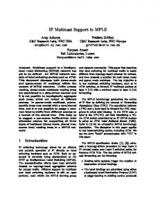
essential models for achieving multi-homing in the IETF approach [7][8][9][13]: intelligent control of the traffic between the ISPs that the site is connected to and achieving the maintenance of transport layer sessions by either breaking the requirement for a single address as a session identifier or by proposing IPv6 protocol stack enhancements for flexible socket management. We note that the focus of the multi6 work is on multi-homed sites, but that supporting this inevitably requires some involvement of IP hosts. In order to get an adequate perspective to the problem of multi-homing in IP access networks defining a set of objectives and requirements is an unavoidable step. Much of the initial creation of the objectives was inspired by the IETF’s objectives to multi-homing [5], which are primarily intended for achieving redundancy in various cases of architectural failures spanning from physical link (interface) failures to failures of various operational aspects of network’s ISPs. Thus, the question of why multi-homing support is needed in MIND/BRAIN access networks can be formulated considering the following objectives: a) Overcoming the weakest links in the chain; The weakest links of a connection in access networks are usually the air interfaces that a terminal (i.e. Mobile Node – MN) uses to access the network. A particular feature of MIND networks is the ad-hoc network fringe consisted of MNs that also function as ad-hoc routers, which use the ad-hoc routing infrastructure to access the fixed access network and/or provide such access for their neighbours (see Figure 1). In such environments the weakest link is also the dynamic connections between neighbouring terminals inside the ad-hoc part. To overcome these weaknesses, more than one connection via one or more air interface and/or several paths through the ad-hoc network fringe could be established to increase the chance for a reliable overall connectivity. b) Increasing bandwidth and adding flexibility; Many times the requirements on downlink and uplink traffic are different. Also, if a terminal is able to use more than one interface to the network, the flexibility and bandwidth can be increased. c) Balancing the load inside the access network; Balancing of the total traffic load in the access network by using more than one path for packets is desirable for achieving redundancy inside the network. d) Achieving redundancy over the backbone; Manipulating inbound and outbound traffic flows in and
PIMRC 2002
beyond the network may allow for further redundancy over the backbone. G lobal Intern et Ser ver s
Fixed/M obile C on ver ged IPv6 C ore N etw ork
ANG D efault wired B RA IN A ccess n etw or k = BA N
N ew ly form e d B A N a s seen by M R s
ANR AN W R
AN W R Self- organisin g M IN D w ir eless access n etw ork
AN R ANR
ANW R AN W R
M N /M R M N /M R M IN D A d-hoc m esh for en abling BA N con n ectivity to all M Rs (also “n esting” access n etw or k h osts)
M N /M R
M N /M R
A N R – A ccess N etw ork R outer A N W R – A ccess N etw ork W ireless R ou ters
Figure 1: A MIND network setup
Figure 1 shows the setup of the IP access network consisting of the BRAIN Access Network (BAN) and the MIND selforganising and ad-hoc network extensions (the stationary MIND access network is still called BAN since the selforganising mesh of wireless routers configures as a part of the wired BAN). This architecture is used in the following investigation of multi-homing scenarios (note that both the ANRs and ANWRs can function as Access Routers (ARs) of the BAN). II. THE MULTI-HOMING SCENARIOS The multi-homing scenarios highlight different aspects of the multi-homing concept by focussing on specific domains in the architecture (for example, within the BAN, or MNs having multiple air interfaces). The identification and analysis of the multi-homing scenarios assists in discovering the multi-homing instances in the network and MNs and provides a basis for the development of solutions. One view to the scenarios could be to regard them as constituents in a series of evolution as depicted in Figure 2. The lines between the components denote direct links or any conceivable intermediate routing infrastructure (e.g., a mesh of intermediate mobile ad hoc network nodes between the MNs/MRs and the BAN). In any case, we assume that either the MN has multiple air interfaces or it has multiple addresses on its interface(s). The following scenarios have been investigated: • Scenario 1: a MN with a single air interface acquires multiple addresses from a single-homed BAN
• Scenario 2: a MN with single air interface acquires multiple addresses from a multi-homed BAN, • Scenario 3: a MN with multiple air interfaces acquires address(es) from a multi-homed BAN • Scenario 4: a MN with one or more air interfaces accesses multiple networks and acquires one or more addresses from the networks. From the MN’s point of view there is not much difference between Scenarios 1 and 2, although the reasons for delivering multiple addresses are different. Since the scenarios share some common issues we look into them in the order of “increasing complexity” where the simpler scenarios can be regarded as being implicitly included in the more ones. A. Scenario 1 – A Non-multi-homed BAN Offering Multiple Addresses to MNs The BAN itself is not multi-homed and the reasons for simultaneously offering multiple addresses to MNs would typically be related to BAN-internal packet forwarding efficiency or QoS provision (although, similar effects could also be achieved with constraint based routing). A specific example is the case when MN is initiating new connections via mobility management in the network and is able to choose between the acquired addresses so that data traffic flows through the most optimal part of the network (see Section III). Other causes for multiple address assignment could be related to attaching BAN-internal QoS profiles to distinct addresses. To support this BAN must be able to offer multiple addresses to MNs and should be able to indicate the preferences (and other selection criteria), and lifetimes. A BAN could exercise policy routing based on the used source addresses. Similarly, MNs should be able to interpret the address preferences, attached QoS expectations, and the urgency for changing to a new address. Despite the above, as concerns radio resource redundancy, the need for establishing additional redundancy mechanisms within an access network is questionable. The micro-mobility protocol of MIND/BRAIN (BCMP [14]) is designed to offer redundancy between access points with a performance that should exceed that of possible alternative mechanisms. B. Scenario 2 – A Multi-homed BAN Offering Multiple Addresses to the MN As already mentioned, site internal multi-homing solutions may require interaction between the host and routing system. The benefits of site multi-homing expand on the benefits already identified in Scenario 1. For example, traffic load could now be shared between ISPs and not only within a BAN. This could be achieved or accompanied with “load-aware” address assignment at the address allocation function in the BAN (although this type of statistical load sharing would be possible without handing out multiple addresses to each MN). In addition, expedited forwarding service or other network services could be available at a specific transit or target network. The BAN should then
ISP
BAN
MN
Scenario 1
ISP
ISP
ISP
ISP
BAN
BAN
MN
MN
+Scenario 2
ISP
+Scenario 3
ISP
BAN
ISP
BAN
MN
+Scenario 4
Figure 2: A schematic view of multi-homing scenarios
ensure that this service is bi-directionally accessible by taking care that all packets having a certain IP source address prefix exit the BAN through this network (see Section III). It is interesting to note that with the introduction of the Home Address destination option, Mobile IPv6 tackles the same ingress filtering problem that we have here. Therefore, Mobile IP mechanisms have been proposed to solve this site multi-homing related issue even for situations where the hosts are not mobile [10]. When applied to BAN access this would mean that a MN (also Correspondent Nodes - CN) behaves as if one of the acquired (and eventually deprecated) addresses were the MN’s Home Address. That is, the deprecated IP address is still used by the applications for identifying connections (inserted in a Home Address Option), whereas a new IP address is transparently used as a Mobile IP CoA (i.e. as the source address of packets). C. Scenarios 3 – A Multi-interface MN Accessing a Single BAN This scenario involves connecting to the same BAN through different routing paths. This can be achieved by using separate interfaces of the MN and/or by connecting to the BAN through diverse routing paths in the ad-hoc mesh. Typically the interfaces would represent different wireless technologies with distinct packet forwarding characteristics. The diverse MN-BAN-connections may be terminated at the same or at different access routers. From the BAN’s point of view, a MN having simultaneous connections to the BAN would look like multiple hosts as regards address assignment and packet routing but, typically, as a single entity as regards AAA functions. The benefit for the MN is that it is able to select the most suitable paths for its traffic flows. For this, connection management in the MN must be provided with enough information for making the policy decisions on interfaces and next hop routers used for new connections. An example could be to always select the cheapest network or the network offering the highest bit rate or lowest delay. There may be other selection criteria related to applications. Additionally, reselection of the routing paths should be possible for the MN’s active connections through session management. In this scenario, intra-domain handovers could be performed at each MN’s interface separately. Additionally, the MN
could hand over transport connections from one interface to another by using global terminal mobility mechanisms. The BAN should not care which one of the MN’s interfaces originates packets with a specific IP source address. If the forwarding requirements for upstream and downstream flows of a single connection are different, the MN should be able to choose inbound and outbound interfaces that best match the asymmetry. This requires that the IP source address of outbound packets is an address of the inbound interface (assuming that a CN uses the MN’s IP source address as the IP destination address for the packets that the CN sends to the MN). On the other hand, the asymmetry can be considered as a negative side-effect when the intention is to move both directions of a connection to another interface without exercising global mobility procedures. However, when the source address does not belong to the outbound interface, ICMP Redirects may not work. Furthermore, the outbound packets should be routable even if the source address is not topologically correct. To make a Mobile IP Home Agent (or a CN) divert separate downstream flows to different access routers, the MN must use different Home Addresses (with bindings to different CoAs) when initiating connections. However, a MN using the per-flow movement technique described in [11], could request a split of its inbound flows. Then, the Home Agent (or a CN) would direct classified downstream flows through specific access router. A MN could also hand over active transport connections from one interface to another by using micro-mobility (BCMP) path updating. However, also here the new address binding would divert all IP traffic (destined to a certain address) towards the new access router. Then the splitting of in-bound flows would facilitate packet forwarding to two or more access points. D. Scenario 4 – A MN Accessing Different Networks In this scenario, a MN is able to connect to different access network through different interfaces. The scenario characteristics are similar to the multi-interface Scenario 3 where the MN attaches to a single BAN with the exception that the metrics related to the access network (e.g., contractual issues and available services) have an impact on the selection of the network interface, and that the MN must perform multiple full logins to networks. Therefore, most of the issues mentioned in Scenario 3 also apply here (when we
replace the term “access router” with “access network”). Handovers may be performed at each interface separately. E. Implication of the Ah-hoc connectivity on the scenarios In MIND ad-hoc network extensions, a single-interfaced MN (or an ad-hoc MR running a MANET protocol) may become virtually multiple-interfaced. Then it would reach the BAN through multiple paths (multiple virtual interfaces or links), and the BAN would see the MN as node having multiple interfaces. A MN may simultaneously attach to multiple ARs through : • multiple physical interfaces using direct links, and/or • multiple virtual interfaces using multiple routing paths through the ad-hoc fringe network. Accordingly, this case of virtual multi-interface connectivity shares the issues of Scenario 3. However, note that the MN may attach through one of its interfaces to the same access router’s interface via multiple ad-hoc routing paths. This case of “virtual link-layer multiplexing” is not seen as a multi-homing situation by BAN but allows for redundancy control by the MN since the next-hop MN (MR) has an influence on the packet forwarding characteristics. A part of our current work deals with creating connection management in MNs for deciding on the use of interfaces and next hop routers by utilising link layer and routing information. III. NETWORK CONFIGURATIONS A. Access Network Configuration Packet forwarding for MNs in MIND/BRAIN access networks broadly corresponds to the mechanisms of mobility management and ad hoc network routing. Mobility management in BAN is solved by BCMP [14] where the basic packet forwarding setup consists of routing packets to the MN’s Anchor Points (ANP) and consequent tunnelling to the AR where the MN is connected. As seen by the routing infrastructure beyond ANPs (in the access network up to the Access Network Gateways – ANG and the outside Internet) routing is performed by regular IP routing protocols. On the other hand, downlink routing from ANPs to AR is controlled by BCMP. This corresponds to the micro mobility domain of Figure 3. Beyond the micro mobility domain, a single operator may, through suitable network configuration define two separate routing domains (A and B, see Figure 3). Assuming that mobility management takes care of redundancy in the micro mobility domain and the radio interface (as discussed in the scenarios, especially Scenario 1) the configuration for redundancy will be an issue for ANP and beyond. An example situation describing the multi-homing problem includes a MN, which receives two CoAs from two ANPs. Through suitable dimensioning, the BAN operator may form two parallel and overlapping Routing Domains in order to make it possible to guarantee routing of packets belonging to different paths through different network elements and links without introducing a new routing scheme for multihoming. Packets originating from the MN have to be routed
from AR to the right Routing Domain (but not necessarily through ANP) depending on the source CoA used. This makes sure that different CoAs also make relevance to the upstream traffic and not just to the downstream traffic. In case of an error in one routing domain the other domain can be used as an alternative routing fabric (eg. by updating its routes using an internal routing protocol). ANG Micro
ISP E
Mobility Domain
MN
Routing Domain A ANP
ANG
AR ANG ANP
ISP F
Routing Domain B ANG
Figure 3: Configuration of Routing Domain
B. Multiple Access Networks A specific example may involve two BANs operated by two different operators. If the two access operators also have different Service Level Agreements with different backbone operators the diversity becomes completed (still we never know for sure that the two operators always use different network resources). In a multi-homed network, we may not only have support for redundancy within the access domain but also in the backbone (ISP E and F) in Figure 4.
CoA - B Access B
CoA - D
ISP E HA
HA
Access D CN
MN
Access A
CoA - A
Access C HA
ISP F
HA
CoA - C
Figure 4. End-to-end Multi-homing
Duplicated Home Agents (HA) (macro mobility by Mobile IP [12]) for supporting multi-access is an option for achieving full redundancy. All CoAs and HAs represent possible reference points. Some of them (all HAs) may be bypassed for optimised routing. The rule of thumb is that packets always have to be originated from the network that has allocated the used IP source address. In Figure 4, it will be the MN’s responsibility to transfer packets through the right AN (A for CoA-A etc.). The cross domain routing might occur as indicated with dotted lines (this shall not be prevented but still avoided in order to guarantee full redundancy).
IV. ACCESS SELECTION A. Single Ended Access Selection / Multi-homing Two parallel paths can be established through two different ANs as shown in Figure 5. If one of these paths is active while the other is standby the requirement on the involved entities (the MN and the HA) becomes fairly simple. The criteria for switching to the standby connection may entirely be defined by the MN. The MN needs to update the HA (via Mobile IP) in order to activate the stand-by path through the access network B after reserving resources over the stand by path assuming that local resource reservation through AN B is possible.
and functional similarities among protocols and related architectures and simplify the needed functionality in multihoming solutions. Additionally, mobility management and multi-homing functions in access networks share some common issues such as packet forwarding procedures and ingress filtering problems. Access B
Standby connection HA CN
MN Access A
Active connection
Standby connection Access B
Figure 6: Multi-homing through Different Access Networks with Load Sharing
HA CN
MN
ACKNOWLEDGMENTS
Access A
Active connection Figure 5: Multi-homing via Different Access Networks
To allow seamless switching between the paths HA would need to support simultaneous bindings for the two paths, i.e. the parallel stand-by path has to be made active (bi-casting) before the actual switching is made. Independent on the reason for switching between one path or access network to another there might be a lot of data in the active path that should be preserved. B. Double Ended Access Selection / Multi-homing In this case, two paths are established all the way between MN and CN even though not both paths are routed differently all the way between the two terminals (i.e. dealt by the same HA as shown is Figure 6). In such a setup load balancing can be used to let voice be routed over one access network while video or data flows traverse the other access network. As seen by a HA (or CN is the routes are optimised) the MN is represented by to CoAs (like two terminals connected to network A and B). A particular challenge for this situation is for applications to combine two separate flows. Solutions like multilink PPP [10] can complement this setup by allowing load balancing and automatic transferring between paths in case of errors. V. CONCLUSIONS This document shows key aspects of multi-homing support in MIND/BRAIN networks by identifying the multi-homing scenarios and some solving mechanisms. Currently our effort is directed towards creating the internal architecture of terminals to benefit from multi-homing by using application awareness and link layer convergence feature for providing monitoring information and controlling the wireless link. Despite the intention to avoid overlaps the analysis of issues mentioned here reveals that the different aspects to multihoming share many benefits, issues, and even approaches to solutions. These overlaps seem to spring from the structural
This work has been performed in the framework of the IST project IST-2000-28584 MIND, which is partly funded by the European Union. The authors would like to acknowledge the contributions of their colleagues from Siemens AG, British Telecommunications PLC, Agora Systems S.A., Ericsson Systems AB, France Télécom S.A., King's College London, Nokia Corporation, NTT DoCoMo Inc, Sony International (Europe) GmbH, T-Systems Nova GmbH, University of Madrid, and Infineon Technologies AG.
REFERENCES [1] IST-2000-28584 MIND, Mobile IP-based Network Developments, www.ist-mind.org. [2] IST 1999-10054 Project BRAIN, Deliverable D2.2, March 2001, www.ist-brain.org. [3] R. Draves, “Default Address Selection for IPv6”, Internet Draft (work in progress), draft-ietf-ipngwg-default-addr-select-06.txt, Sep.2001. [4] M.Bagnulo, A. Garcia-Martinez, A. Azcorra, D. Larrabeiti, “Survey on proposed IPv6 multi-homing network level mechanisms”, Internet Draft (work in progress), draft-bagnulo-multi6-survey6-00.txt, July 2001. [5] B. Black, V. Gill, J. Abley, “Requirements for IPv6 Site-Multihoming Architectures”, Internet Draft (work in progress), draft-ietf-multi6multihoming-requirements-02.txt, Nov. 2001. [6] R. Braden, “Requirements for Internet Hosts – Communication Layers”, RFC 1122. [7] J. Jieyun, "IPv6 multi-homing with route aggregation", Internet Draft (work in progress) draft-ietf-ipng-ipv6multihome-with-aggr-00.txt, Nov. 1999. [8] T. Bates, "Scalable support for multi-homed multi-provider connectivity", RFC 2260. [9] J. Hagino, "IPv6 multi-homing support at site exit routers", RFC 3178. [10] W. Townsley, A. Valencia, A. Rubens, G. Pall, G. Zorn, B. Palter, “Layer Two Tunnelling Protocol ‘L2TP’”, RFC 2661. [11] H. Soliman, K. El Malki, and C. Castelluccia, “Per-flow movement in MIPv6”, draft-soliman-mobileip-flow-move-01.txt, Internet Draft (work in progress), Nov. 2001. [12] D. Johnson, C. Perkins, “Mobility Support in IPv6”, Internet Draft (work in progress) draft-ietf-mobileip-ipv6-16.txt, Mar. 2002. [13] N. Bragg, "Routing support for IPv6 multi-homing", Internet Draft(work in progress), draft-bragg-ipv6-multihoming-00.txt, Nov.2000. [14] C. Keszei, N. Georganopoulos, Z. Turanyi, A. Valko, “Evaluation of the BRAIN Candidate Mobility Management Protocol”, IST Summit Barcelona, Sep. 2001.