postprocessing steps, the actual data taken from a real human motion plays an important role as .... time and the velocity vector back to the originals, the reversed motion curve becomes a solution ..... 8] Milnor, J., Morse Theory, Princeton Univ.
In Computer Graphics and Applications , (Proc. of Paci c Graphics '95 , Seoul, Korea, August 21{24, 1995), S.Y. Shin and T. Kunii (Eds.), World Scienti c, pp. 118{132.
Pseudo Dynamic Keyframe Animation with Motion Blending on the Con guration Space of a Moving Mechanism Joo-Haeng Lee and Myung-Soo Kim Dept. of Computer Science POSTECH Pohang 790-784, South Korea.
Abstract
This paper presents an e�ective way of generating and controlling dynamic motions of a multi-linked body system while interpolating given boundary conditions. The basic idea is based on smoothly blending two dynamic motion curves in the Con guration space of a moving mechanism. Given a time interval [ 1 2], two motion curves 1 ( ) and 2( ), 1 � � 2 , are generated by physical simulation so that they satisfy the boundary conditions at = 1 and = 2 , respectively. The two curves are then smoothly blended on the Con guration space so that the blended motion curve satis es the boundary conditions at = 1 and = 2 . Higher degree blending functions provide extra degrees of freedom in controlling the generated motion in the middle of the time interval [ 1 2]. It is straightforward to extend the motion blending technique to keyframe animation. Compared with the conventional animation techniques for a multi-linked body system, the motion blending technique achieves not only computational e�ciency but also pseudo dynamic motions by incorporating the merits of each of the previous methods within one system. t ;t
C
t
C
t
t
t
t
t
t
t
t
t
t
t
t
t ;t
Keywords: Keyframe animation, dynamics, Euler-Lagrange Equation, Con guration space, phase space, motion blending 1
Introduction
In commercial animation movies, the motion of a character is usually generated by keyframe animation technique. However, this technique is quite laborious and requires considerable talent in order to generate natural motion. There are relatively few computer animators who can produce animation of a quality comparable to that of a Walt Disney animation movie. An immediate goal of computer animation research is to develop appropriate animation tools which enable even the novice to produce natural character motion. Since most end users of computer animation softwares are graphic artists, it is also important to develop animation tools which are easy to use and understand. Keyframe animation, in spite of its other shortcomings, is popular in such softwares primarily because it is easy to use. Although many techniques have been developed for character animation, the most powerful tool currently is still the straightforward method of motion recording, rotoscoping . For a human-like character with arms and legs, the easiest way to generate a walking motion is to record the actual human walking data and postprocess them in accordance with what appears most appropriate to 1
the character. Simple postprocessing techniques include scaling and local modi cations, etc. One can easily manipulate the motion data once the data have been tted with spline curve segments, but the stepping motion of a character introduces singularities on the motion curve. For these postprocessing steps, the actual data taken from a real human motion plays an important role as a standard natural motion. The approach of this paper is based on a similar strategy. We start with some natural dynamic motions of a moving mechanism and modify them by using a blending technique to generate a pseudo dynamic motion. The initial motion data can be obtained from any of the previous animation techniques. One simple way of generating them is by doing forward dynamic simulations on the moving mechanism. Dynamic simulation usually produces natural dynamic motion; however, it is very di�cult to make the resulting motion satisfy both the initial and nal boundary conditions simultaneously. This is the reason why the SC (Spacetime Constraint) method is promising in computer animation since the SC method generates motion which satis es all the constraints including the boundary conditions [5, 7, 10, 14]. However, the SC method is based on a non-linear optimization technique, which is computationally quite intensive since the optimization is done on the motion curve itself. Moreover, further modi cations to the generated motion require repeated recomputing of the entire optimization. The process of making an animation movie usually involves a lengthy sequence of repetition and local modi cation. As a result, it is very important to devise a new method which may reuse some of the previous motion data and, at the same time, support local modi cations e�ciently. The motion blending method suggested in this paper overcomes the drawback of physical dynamic simulation and generates a motion curve which satis es the boundary conditions at both initial and nal keyframes. This is done by blending two dynamic motion curves, each satisfying one of the two boundary conditions; the resulting blended motion curve satis es all the boundary conditions. Many e�cient methods have been developed for forward dynamic simulation [2, 3, 4, 6, 12, 13]; based on simulating the law of physics, they produce quite natural dynamic motions. The blended motion curve generates slightly less natural dynamic motion; however, this is inevitable when the motion curve must satisfy all the boundary conditions. The SC method tries to minimize awkwardness by optimizing the external energy consumed during the motion. The input motion curves of the motion blending method are not only limited to those generated by forward dynamic simulation. Any pair of motion curves can be used for blending as long as each boundary condition is satis ed by at least one of them. It is also allowed for only one curve to satisfy both initial and nal conditions, while the other satis es neither. For example, the motion curve generated by the SC method can be blended with any other motion curve for local and/or global modi cations. This capability would make the SC method more powerful as an animation tool by providing a way to easily modify and control the generated motion curve. This method can also be generalized to the case of blending three or even more motion curves, in which case, the blending function is required to have a higher dimension. Furthermore, by using a high degree blending function with extra degrees of freedom, we can easily make the motion blending method switch into a variant of the SC method, in which the extra degrees of freedom become the parameters to be optimized in the non-linear optimization process. By choosing an appropriate set of basic motion curves to be blended and the parameters for the extra degrees of freedom in the blending function, we can signi cantly reduce the size of non-linear optimization for the SC method. The motion curve thus generated can also be used as an initial solution for the more precise SC method. By using a suboptimal solution as an initial solution, the non-linear optimization process may converge very quickly. The rest of this paper is organized as follows. In x2, the underlying geometry for motion blending 2
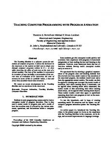
q2 Ea (q a , q a ) (q b , q b )
Eb
q1
0
q1
q2
Figure 1: Phase Flows on Energy Level HyperSurfaces is explained. It is based on the concept of phase ow on an energy level hypersurface embedded in the phase space. In x3, the motion blending technique is applied to the keyframe animation of (i) a ball of mass m and (ii) a multi-linked open-chain. Finally, we conclude this paper in x4.
2
Phase Flows on Energy Level Hypersurfaces
In this paper, we interpret the motion of a moving mechanism as a geometric curve in the Con guration space of the mechanism. In classical mechanics [1], the Con guration space is parametrized by generalized coordinates q = (q1 ; : : :; q ) 2 R , and the phase space of the mechanism is parametrized by (q; q_ ) = (q1 ; : : :; q ; q_1; : : :; q_ ) 2 R2 . The dynamic motion curve following the law of physics is given by the integral curve q(t) which satis es the following Euler-Lagrange Equation: n
n
n
n
n
d @L ? @L = ?; dt @ q_ @ q
(1)
where L is the Lagrangian and ? is a generalized external force to the mechanism. In the above equation, we can observe that the equation holds even if we change t into ?t and q_ into ?q_ . That is, by reversing the time and the generalized velocity vector, we can also generate a natural dynamic motion that satis es the Euler-Lagrange Equation. After we compute the solution, by reversing the time and the velocity vector back to the originals, the reversed motion curve becomes a solution to the original Euler-Lagrange Equation. In this way, we generate a natural dynamic motion curve which satis es the nal conditions at the end of the curve. Dynamic simulation performed in this way is called backward simulation. When there is no external force exerted on the mechanism, the total energy is preserved and the phase ow curve lies on the same energy level hypersurface (see Figure 1). When the boundary 3
conditions given at the initial and nal keyframes produce di�erent levels of energy, we need to exert external forces onto the system so that the phase ow curve smoothly deviates from one energy level hypersurface and ows to the other energy level hypersurface. When the transition is made in such a way that the intermediate energy level changes monotonically, it is clear that the total external force exerted is optimal. However, the monotonicity of energy level provides only a su�cient condition for the motion curve to become an optimal solution. In most cases, an optimal motion curve produces the energy transition in an oscillating fashion. The energy consumption mainly depends on the given keyframe boundary conditions. For example, consider the problem of interpolating two keyframes (p ; v ) of a point p, i = 1; 2, where the two positions p1 and p2 are at a long distance and the two velocities are v1 = v2 = 0. The motion curve p(t) should have a high speed in the middle of the curve so that it can travel over a long distance from p1 to p2. Though the kinetic energy is 0 at the two boundary keyframes, the high speed in the middle of the curve introduces a high kinetic energy. Therefore, even an optimal motion curve would experience an energy jump in the middle of the curve. The energy minimization problem as discussed above presents di�culties, mainly because the energy level surface is a hypersurface in the phase space (parametrized by (q; q_ )), not in the Con guration space of the moving mechanism. Instead of directly manipulating the hypersurface in the 2n-dimensional phase space, we project two phase ow curves (each corresponding to one of the two boundary conditions) into the Con guration space. It is clear that the two projected motion curves C1(t) and C2(t) maintain their respective energy. The motion blending technique generates a motion curve C (t) in the Con guration space by blending the two motion curves C1(t) and C2 (t) as follows: C (t) = 1 ( ) 2( )(f (t)); for t1 � t � t2 ; where 1 ( ) 2( )(s), 0 � s � 1, is the geodesic path which connects two points C1 (t) and C2(t) in the Con guration space. We assume the Con guration space is a complete Riemannian manifold in which the geodesic between any two points is de ned [8, 11]. One may wonder why we do not blend the two phase ow curves directly in the phase space. By doing this in the phase space, it becomes quite di�cult to make the resulting blended phase curve (q(t); q_ (t)) satisfy the necessary condition between the two components q(t) and q_ (t): i
i
C
C
t ;C
t ;C
t
t
d q(t) = q_ (t): dt However, when we rst construct the motion curve C (t) in the Con guration space, the corresponding phase curve is automatically generated as (C (t); C 0(t)) in the phase space. With an appropriate
blending function, the phase curve satis es the two boundary conditions. Given a phase curve (C (t); C 0(t)), we can examine the change of total energy T (C 0(t))+ U (C (t)) and see if the energy level change is monotonic, where T (C 0(t)) is the kinetic energy and U (C (t)) is the potential energy of the motion. If the total energy change is almost monotonic, the energy consumption would also be almost optimal. Otherwise, when there is a big energy level jump, we may try to use other blending functions to generate a motion curve that consumes less energy. When the blending functions are formulated with extra degrees of freedom, an optimization can be performed over the parameters for the extra degrees of freedom. Nevertheless, in many test examples, we have not observed much improvement by using di�erent blending functions. This means that the motion blending curves are usually very close to the optimal solutions and the energy level jumps are somewhat inevitable due to the given keyframe conditions. 4
3
Motion Blending
3.1 Ball of Mass m
To illustrate the basic idea of motion blending technique, we rst consider a simple example of throwing a ball of mass m. Assume the ball has position p(t) and velocity v (t) at time t, and p = p(t ) and v = v(t ) for i = 1; 2. The Lagrangian L(p; v) is given by: L(p; v) = T (v) ? U (p); where T (v ) is the kinetic energy and U (p) is the potential energy. They are given by: T (v) = 12 m < v; v >; and U (p) = ?m < g; p >; where g is the gravitational force and < v1; v2 > denotes the inner product of two vectors v1 and v2 . When there is no external force, the Euler-Lagrange Equation (1) reduces to: i
i
i
i
d @L @L dt @v ? @p = 0 d dt mv + mg = 0 mv_ + mg = 0 v_ = ?g
The velocity v (t) is given by:
v(t) = v1 +
Z
t
t1
vdt _ = v1 +
Z
t
t1
?gdt = v ? g(t ? t ): 1
1
The forward simulation produces a path C1(t):
C1(t) = p1 +
Z
t
t1
(v1 ? g (t ? t1 )) dt = p1 + v1 (t ? t1 ) ? 12 g (t ? t1 )2:
Similarly, the backward simulation produces a path C2(t): C2 (t) = p2 + v2(t ? t2 ) ? 12 g(t ? t2 )2: The motion blending generates a path C (t): C (t) = (1 ? f (t))C1(t) + f (t)C2(t); where f (t) is a blending function which satis es the following conditions: f (t1 ) = 0; f (t2 ) = 1; f 0(t ) = 0; for i = 1; 2: One can easily check that the motion blending curve C (t) satis es: C (t ) = C (t ) and C 0(t ) = C 0(t ); for i = 1; 2: To avoid a jump in the acceleration of the motion blending curve at each keyframe, we also need to enforce the following second derivative condition to the blending function: f 00 (t1 ) = 0 and f 00(t2 ) = 0: i
i
i
i
i
5
i
i
y Backward Simulation Blended Path
Forward Simulation
0
x
Figure 2: Throwing a Ball of Mass m
E
Backward Simulation Forward Simulation
Blended Energy
0
t
Figure 3: Total Energy Graph
6
f(t) 1
0
0.5
1
t
Figure 4: Graphs of Blending Functions Figure 2 shows the result of a motion blending for throwing a ball of mass m in the xy plane. Figure 3 shows the total energy change of the ball under motion. The total energy jumps signi cantly in the middle of the motion. The energy jump is due to the following velocity property of the motion blending curve:
C 0(t) = (1 ? f (t))C10 (t) + f (t)C20 (t) + f 0 (t)(C2(t) ? C1(t)): The rst part of the velocity: (1 ? f (t))C10 (t) + f (t)C20 (t) essentially blends the velocities of two component curves and generates no larger speed than kC10 (t)k or kC20 (t)k when 0 � f (t) � 1. The second part: f 0 (t)(C2(t) ? C1 (t)) becomes large when the position di�erence: C2(t) ? C1(t) has a large magnitude in the middle of the curve. The slope of the blending function f (t) usually becomes larger in the middle of the time interval [t1 ; t2]. (Figure 4 shows a set of blending functions which interpolate di�erent values at t = 0:5.) The velocity component f 0 (t)(C2(t) ? C1 (t)) becomes much larger in the middle of the curve and the kinetic energy increases by the square of the amount of the velocity component. As a result, when we have extra degrees of freedom in generating a family of blending functions, it is better to choose f (t) for which the derivative f 0 (t) changes almost inverse proportionally to the magnitude kC2(t) ? C1(t)k. Although a better choice of the blending function f (t) may reduce the maximum magnitude of energy jump, the improvement mainly depends on the two boundary conditions. Even if the kinetic and potential energies are similar at both initial and nal keyframes, a big energy jump occurs when the boundary conditions are given in such a way that the forward and backward simulation motion curves are much di�erent (see Figures 5-6). We may generate many other motion curves by changing the blending functions and selecting the one that has an optimal energy change. Figures 7{8 show the motion blending paths and their energy graphs, respectively, which result from di�erent blending functions. The original path and energy graph are drawn with dark curves. Also shown are the path and engergy graph of the optimal solution obtained by the SC method. They are drawn with light curves. We can try to reduce the maximum energy jump by scaling down the velocity at the maximum energy peak at time t = t3 and repeating the motion blending procedure for each of the time subintervals [t1; t3 ] and [t3 ; t2]. However, we have observed new energy peaks occurring on both of the two time subintervals (see Figure 9). 7
y Blended Path Forward Simulation
Backward Simulation
x
Figure 5: Example with High Intermediate Speed
E
Blended Energy
Forward Simulation Backward Simulation
0
t
Figure 6: Total Energy Graph
8
E
Forward Simulation Backward Simulation
0
t
Figure 7: Paths Resulting From Di�erent Blending Functions y
Forward Simulation Backward Simulation
x
Figure 8: Di�erent Energy Graphs E
Blended Energy [t1, t3]
Original Blended Energy [t1, t2]
Blended Energy [t3, t2]
0 t t1
t3
t2
Figure 9: New Energy Peaks
9
3.2 Open-Chain Multi-Linked Body System
We consider how the motion blending technique can be applied to the case of open-chain multilinked body system. There are many ways to formulate the multi-link body kinematics and dynamics [2, 6, 9, 12, 13]. For the implementation here, we use the explicit formulas developed in Reference [9] for the Lagrangian and the kinetic and potential energy terms. The formulas are very compact using Lie group and Lie algebra notations. Although they are somewhat di�cult to read, the compact formulations signi cantly reduce numerical errors in the dynamic simulation. Given an open-chain multi-link body system with n joints with joint angles: � = (�1 ; : : :; � ), the total kinetic energy T (�; �_) is de ned by: T (�; �_) = 12 �_ M (�)�;_ where M (�) 2 R � is the manipulator inertia matrix (see [9] for more details). The total potential energy U (�) is given by: U (�) = m gh (�); n
T
n
n
X n
i
i
i=1
where m is the mass of the i link, g is the gravitational force, and h (�) is the height of the center of mass of the i link. Combining the two terms, the Lagrangian is given by: L(�; �_) = 12 �_ M (�)�_ ? U (�) M (�)�_ �_ ? U (�): = 12 th
i
i
th
T
X n
ij
i
j
i;j =1
The equation of motion is given by substituting the above equation into the Euler-Lagrange Equation (1):
d @L ? @L = ? ; for i = 1; : : :; n; dt @ �_ @� i
i
i
where ? represents the actuator torque and other nonconservative generalized forces acting on the i
i joint. The equation of motion can be written as follows: th
M (�)� + C (�; �_)�_ + N (�; �_) = �; where the matrix C (�; �_) 2 R � is the Coriolis matrix for the manipulator, � is the vector of actuator torques, and N (�; �_) includes gravity terms and other forces which act at the joints (see [9] for more details). The physical forward simulation is done by computing the solution � of the above linear system at each time step, which gives the second derivatives of the joint angles with respect to time. This means that we need to integrate the second derivatives to obtain the angular velocity and the angle of each joint. After they are determined, the matrices M (�), C (�; �_), and N (�; �_) are updated in the linear system. Now, for the new linear system, we need to solve the solution � at time t + �t for the forward simulation and at time t ? �t for the backward simulation. The same procedure is repeated and the simulation results are blended using an appropriate blending function. In this case, the motion blending is applied to the joint space of the multi-linked body system, which is the Con guration space of the system. n
n
10
(a)
(b)
(c)
Figure 10: Blended Motion of Two-Segmented Body
11
(a)
(b)
(c)
Figure 11: Blended Motions of Eight-Segmented Body
12
E Backward Simulation
Forward Simulation
Blended Energy
t
Figure 12: Energy Graph for Two-Segmented Body
E Backward Simulation
Forward Simulation Blended Energy
t
Figure 13: Energy Graph for Eight-Segmented Body
13
Figures 10{11 show two animation sequences of a multi-linked body system which are generated by the motion blending technique. In each animation sequence, the left column shows the result of a forward simulation, the right column shows the result of a backward simulation, and the middle column shows the motion blending result of the left and right columns. Figures 12{13 show the total energy graphs for the two animation sequences. The blended motion looks pseudo dynamic and quite natural in the real animation; the motion also satis es both the initial and nal keyframe conditions. The motion blending result can be easily modi ed by using other blending functions while satisfying the boundary conditions. But, in these examples, we have included neither the collision detection nor the angular constraint for each pair of consecutive links.
4
Conclusion
In this paper, a new technique is proposed that blends two physically simulated dynamic motions of a moving mechanism. The result is a pseudo dynamic motion of the moving mechanism that satis es the given keyframe boundary conditions. The motion blending technique is a hybrid method that combines the merits of previous methods in that: 1. A purely kinematic keyframe animation system can be easily upgraded so that it can also include a certain level of dynamic realism. 2. A forward physical simulation method can be easily adapted so that it generates a motion which satis es both the initial and nal boundary conditions. 3. An optimal motion curve generated by the Spacetime Constraint method can be easily modi ed without repeating the time-consuming non-linear optimization process. 4. The space of blending functions provides a low dimensional space to which the Spacetime Constraint method can be applied. The space has a much lower dimension compared with the space of motion curves to which the conventional Spacetime Constraint method has been applied. These advantages are obtained at slight expense to motion realism. However, the resulting motion is not far from an optimal solution. The mathematical tools provided by the phase space and the kinetic and potential energy terms can also play an important role in analyzing the behavior of various other motion curves. They are not limited to the motion blending curves we have discussed in this paper.
References [1] Arnold, V.I., Mathematical Methods of Classical Mechanics , Second Ed., Springer-Verlag, New York, 1989. [2] Armstrong, W.W., and Green, M.W., \The dynamics of articulated rigid bodies for the purposes of animation," Proceedings of Graphics Interface '85 , Canadian Information Processing Society Toronto, Ontario, Canada, PP. 407-415. [3] Barzel, R., Physically-Based Modeling for Computer Graphics, Academic Press, San Diego, CA, 1992, pp. 14{24. 14
[4] Badler, N., Barsky, B., Zeltzer, D., Making Them Move, Morgan Kaufmann, San Mateo, CA, 1991, pp. 269{271. [5] Cohen, M., \Interactive Spacetime Control for Animation," Computer Graphics (Proc. of SIGGRAPH '92) , Vol. 26, No. 2, pp. 293{302, 1992. [6] Ho�mann, C., and Hopcroft, J., \Simulation of Physical Systems from Geometric Models," IEEE Trans. on Robotics and Automation , Vol. 3, No. 3, pp. 194{206, 1987. [7] Liu, Z., Gortler, S., and Cohen, M., \Hierarchical Spacetime Control," Computer Graphics (Proc. of SIGGRAPH '94) , pp. 35{42, 1994. [8] Milnor, J., Morse Theory , Princeton Univ. Press, Princeton, 1963. [9] Murray, R., Li, Z., and Sastry, S., A Mathematical Introduction to Robotic Manipulation , CRC Press, Boca Raton, Florida, 1994. [10] Ngo, J., and Marks, J., \Spacetime Constraints Revisited," Computer Graphics (Proc. of SIGGRAPH '93) , pp. 343{350, 1993. [11] Spivak, M., A Comprehensive Introduction to Di�erential Geometry , Vol. I, Publish or Perish, Inc., Berkeley, 1970. [12] Wilhelms, J., \Using Dynamic Analysis for Realistic Animation of Articulated Bodies," IEEE Computer Graphics and Applications , Vol. 7, No. 1, pp. 12{27, 1987. [13] Wittenburg, J., Dynamics of Systems of Rigid Bodies , B.G. Teubner, Stuttgart, 1977. [14] Witkin, A., and Kass, M., \Spacetime Constraints," Computer Graphics (Proc. of SIGGRAPH '88) , Vol. 22, No. 4, pp. 159{168, 1988.
15