ULTRASONIC BEACON-BASED LOCAL POSITION SYSTEM USING BROADBAND PN (PSEUDO NOISE) - CHIRP CODES Yun Lu Communications Laboratory Dresden University of Technology 01062 Dresden, Germany email:
[email protected] ABSTRACT This work presents the development of a Local Positioning System (LPS), based on the transmission of ultrasonic signals, which have been previously encoded by PN (Pseudo Noise) - chirp codes. The LPS consists of several ultrasonic emitters located at known positions in the deployment environment, and of a portable receiver that computes its position by measuring the Time-of-Flight (TOF) or the Time Difference-of-Arrival (TDOA) between each reference emitter and receiver depending on applications. In this paper the Gold-chirp codes and LS (Loosely Synchronous) -chirp codes as examples will be presented. This exhibits flexible system accuracy and update rate by scaling the chirp duration. Furthermore, the channel model between emitters and receivers is very different in terms of different indoor environments. The problems, which are caused by Inter-Symbol-Interference (ISI) and MultipleAccess-Interference (MAI), can also be improved by using PN-chirp codes with scalable sequence length. Finally the system with PN-chirp codes could be working with lower power in comparison with the system by only using PN codes with rectangular pulses for the same coverage. KEY WORDS Ultrasonic LPS, PN-chirp codes, Polled-Privacy-Oriented system, flexibility, high accuracy, low power.
1 Introduction In recent years, interest in location- and positioningsystems has increased significantly. Location is an essential element of context- a key requirement for context-aware, pervasive computing systems [1]. The explosive development of GPS [2] based navigation systems together with wireless computing and communication technologies, such as PDAs and 3G, is changing the way we live and work. One of the disadvantages of GPS systems is that, due to the attenuation of RF signals, they do not provide fine and fast indoor location estimates, or even nothing. A number of systems have been proposed to address this problem including WLAN location, dedicated Radio Frequency (RF) location and ultrasonic location systems [3], [4]. This paper considers the problem of accurate, robust indoor ultrasonic location. Ultrasonic location systems have three ad-
Adolf Finger Communications Laboratory Dresden University of Technology 01062 Dresden, Germany email:
[email protected] vantages over RF based systems. Firstly, the lower speed of propagation of ultrasonic signals facilitates accurate ranging. Secondly, ultrasonic signals do not propagate through walls and so are easier to model and control for indoor environment. Thirdly, RF systems are prohibited or unusable in certain situations, for example in hospitals, on ships and underwater. Indoor ultrasonic location systems for pervasive computing were first studied in Bats [1] and Crickets [5] [6] systems in MIT. The Bats system employs infrastructure location with impulsive signalling. In response to an RF pulse, the mobile ’Bat’ transmits an ultrasonic pulse which is detected by receivers on the walls and ceiling. The infrastructure then estimates the position of the Bat. The Crickets system utilizes transmitting beacons and receiving mobile device. Again, a simple ultrasonic pulse with RF synchronization is used for TOA (Time of Arrival) estimation. The accuracy of the systems is reported to be 10 cm and an orientation accuracy of 3 degrees in low noise environments. The accuracy of the systems deteriorates rapidly in noise. The update rate of the systems is limited since time must be allowed for the reverberation of the pulses to decay before resending. The application of Direct Sequence Spread Spectrum (DSSS) signalling for ultrasonic location has been investigated previously. In [7], the authors describe construction of a wideband ultrasonic transducer. The transducer was found to have a response of 20-100 kHz. The author reports that a location system using the transducer has an accuracy of just over 2 cm under conditions of typical noise. There are other systems, like [8], where the authors use a transducer with a response of 4-100 kHz and an accuracy of 2 cm. The problem of the simultaneous emission of the ultrasonic signals was solved by using DS-CDMA. But the efficiency of these systems strongly depends on the SS (spread spectrum) codes that codify the ultrasonic emissions. Those codes should provide very low crosscorrelation (CC) values to avoid the MAI; and very low auto-correlation (AC) sidelobes to reduce the ISI. The Gold codes [2] provide both relative good AC and CC properties. The optimal solution to combat ISI and MAI is the LS codes [2], which exhibit an Interference Free Window (IFW), where the aperiodic AC sidelobes and CC values are zero. Consequently, if the time-offsets between the codes, expressed in terms of number of chips intervals, are within
the IFW, both ISI and MAI can be eliminated thoroughly. However, because of the fixed sequence length the AC and CC properties for Gold codes and the width of IFW for LS codes are not changeable, which lead to the problems that the accuracy of system with Gold codes is fixed and for LS codes the desired signal will not be detectable, when they are outside the IFW. The contribution of this work is the design of an ultrasonic LPS, which uses Gold or LS codes combining with flexible chirp pulses with great flexibility depending on system requirements and the channel models, which could be very different in terms of indoor environments. By using the combined codes not only the system performance will be improved (that is to say, we could send signal energy depending on system requirement without wasting the system capacity and at the same time change the system update rate easily) but also the spectrum of application will be enlarged.
its location. The mobile units do not rely on outside entities to perform measurements or location calculations, and do not advertise their presence. In this paper we introduce another system, namely the Polled-Privacy-Oriented system. Polled means that beacons are told when to send their ranging signals. Normally the system works in PrivacyOriented mode (signals are transmitted continuously and periodically, Successive Interference Cancellantion (SIC) [9] is introduced to deal with near-far effect). When a receiver tries to demodulate a signal, which is much weaker than other signals, the cross-correlation peaks due to those other signals can become significant, and the detector may be unable to resolve the weak signal. In this case the system can turn into Polled (signal power controll via radio back channel, which based on channel estimation)-PrivacyOriented mode. That is to say, the system works in PrivacyOriented mode for normal receivers and polled mode for the receiver, which has significant problem of near-far effect. These two modes could be time shared.
Beacon 4 4
Beacon 5
Beacon 2
3
Beacon 3
Theory of ranging codes
3 Z (m)
Beacon 1 2
1 MR 0 5
MR 4
5 3
4 3
2
2
1 Y (m)
0
1 0
X (m)
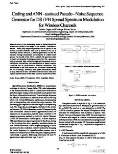
Figure 1. System architecture with mobile robot (MR) This paper is organized as follows: Section 2 presents the system structure of ultrasonic LPS. In Section 3 the theory of ranging codes are described. The simulation methods are described in Section 4. Finally, the results and conclusions are outlined in Section 5 and 6.
2 System structure Fig. 1 shows a schematic representation of the system structure of the proposed LPS. A set of hardware synchronized beacons are placed at known positions in the environment, and all of them cover a determined area by emitting simultaneously and periodically (PrivacyOriented system). For every beacon a different PN-chirp code will be assigned. A non-limited number of portable receivers compute their own positions from the measurement of TOFs (beacons and receiver are synchronized by wireless network) or TDOAs (it is not necessary a synchronism trigger signal (RF, IR, etc) between beacons and receiver) depending on applications, according to multilateration algorithm. At every position, the specific portable receiver has to detect at least 4 beacons for 3D positioning for TOFs. Each receiver can independently compute
As described above all beacons are active at the same time. The ranging signals from beacons will be received asynchronously at the mobile units. The favourable correlation properties of Gold codes are achieved by synchronizing all Gold codes from beacons. That is to say, there is no time shift between two Gold codes. If the codes are not synchronized, it may raise a situation: Gold code i has time shift tv in comparison with Gold code j. Temporally adjacent pulses of the Gold code i could have different signs. For the suppression of the Gold code i is therefore not determined by usual cross-correlation function, but the so called odd cross-correlation function. In this case it may lead to bad property of cross-correlation function, which could have relative large AC sidelobes and CC values. Furthermore, the Gold codes with duty cycle 1 are disruptible in the case of broadband jamming. To combat those problems, the Gold codes with duty cycle smaller than 1 are introduced. The probability that the mainlobe of AC is disturbed by broadband jamming by correlating with reference signal, is therefor become small. Fig. 2b shows an example of PN code with duty cycle 0.1. We now turn our attention to the system performance with asynchronous Gold ranging signals with scalable duty cycle. The ultrasonic system is assumed that there are K beacons. The k-th beacon is assigned a Gold code waveform a(t) which consists of a periodic sequence of unit amplitude, positive and negative datas akj , rectangular pulses of duration Tc . We could write ak (t) as ak (t) =
∞ X
akj PTc (t − jTc ) PTc /γ (t − jTc /γ) ,
(1)
j=−∞
where Pτ (t)=1 for 0≤t≤τ and Pτ (t)=0 otherwise, γ is the duty cycle of Gold codes. We analyse the signals on baseband. Thus, the transmitted signal for the k-th user is sk (t) =
√ p · ak (t) ,
(2)
For the case 0≤lTc ≤τ ≤(l+1)Tc ≤T and γ=1 these two cross-correlation functions can be written as
1 0.5
Rk,i = Ck,i (l − N )Tc
T 0 −0.5
0 Rk,i
−1 0
2
4
6
8
(a)
10
(8)
= Ck,i (l)Tc + [Ck,i (l + 1) − Ck,i (l)](τ − lTc ) ,
(9)
where Ck,i is the discrete aperiodic cross-correlation func√ tion. The desired signal component of Zi is pN Tc hi0 while the variance of the noise component of Zi is
ms
1 T
0.5
+ [Ck,i (l + 1 − N ) − Ck,i (l − N )](τ − lTc )
( p var(Zi ) = N Tc
0 −0.5 −1 0
2
4
6
8
(b)
Figure 2. PN codes (rectangular pulse) with duty cycle 1 (a) and (rectangular pulse) with duty cycle 0.1 (b)
r(t) =
K X n X
hkj
√
p ak (t − τkj ) + n(t) ,
(3)
k=1 j=0
where hkj is the coefficient of channel impulse response to time shifts τkj , n is the number resolvable echoes and n(t) is white noise. We also assume that the time shift τkj of reflected signals are uniformly distributed on the interval [0, T ], where T is the Gold sequence duration and N is the sequence period. If the received signal r(t) is the input to a correlation receiver matched to si (t), the output is Z
r(t)ai (t)dt .
+
√ pN Tc hi0 | {z }
p(N Tc )2 var(Zi ) = 3N 3 +
N0 Tγ . 2
The average SNR is p var(Zi ), which is
+
√ p
{z
| Z + |0
(
+
T
(5)
white noise
where hij is the channel impulse response of ij-th reflected signal, m, n are the number of resolvable reflected sigb and R b0 are the continuous-time parnals. Furthermore, R tial cross-correlation functions defined by Z Z
τ
ak (t − τ )ai (t)dt
(6)
ak (t − τ )ai (t)dt .
(7)
0 T
0 bk,i R (τ ) = τ
SNR ≈
}
MAI
bk,i (τ ) = R
h2ij γ
ri,ij +
n K X X
) h2kj γ
ri,kj
k=1 j=0 k6=i
(11)
√
pN Tc hi0 divided by the RMS noise
(12)
with the approximation in [10]:
n
n(t)ai (t)dt , {z }
N0 T γ . (10) 2
K X
ri,k ≈
K −1 . 3N
(13)
The average SNR could be rewritten as
}
{z
m X
k=1 k6=i
√ XX 0 bi,kj (τkj − τi0 ) + R bi,kj + p hkj [R (τkj − τi0 )] k=1 j=0 k6=i
+
√ pN Tc hi0 , SNR = p var(Zi )
ISI K
− τi0 )]d(τkj − τi0 )
j=1
0 bi,ij (τij − τi0 ) + R bi,ij hij [R (τij − τi0 )]
j=1
|
(
(6N 3 )−1
desired signal m X
)
This is then written as follows with the substitution PN −1 µk,i (n)= l=1−N Ck,i (l)Ck,i (l + n) and rk,i =2µk,i (0) + µk,i (1) in [10].
0
Zi =
2 [Ri,ij (τij − τi0 )
0
02 Ri,kj (τkj
(4)
The output of the correlation receiver at t=T is given by
T 0
j=1
k=1 j=0 k6=i
T
Zi =
Z h2ij γ
02 + Ri,ij (τij − τi0 )]d(τij − τi0 ) Z T K n XX 2 (τkj − τi0 ) [Ri,kj + h2kj γ
10 ms
where p represents the common signal power. To estimate the average SNR at the output of the correlator i of receiver, we have to take three terms into account, namely the MAI, ISI and white noise. The received signal is given by
m X
2γ h2i0
½X m
N0 2Eh2i0
n
h2ij
j=1
X 2 K −1 1 + hkj 3N 3N j=0
¾
)− 1 2
,
(14)
where E is the energy of ranging signal. From (14) we could find that the average SNR is changed by scaling the duty cycle γ while the sequence period N staying constant. That is to say, we can change the system accuracy and update rate depending on requirements by changing the duty cycle of Gold codes. In practice, the requirement of accuracy may not be the same for all applications and also not be same for all the time. This means we can reduce the system update rate for slow-moving robot with better accuracy or increase the update rate for fast-moving robot with
LS code
LS−chirp code
800
800
1
600
600
0.5
400
400
0
200
200
0
0
−200
0
2 4 Duty cycle=1 IFW=1ms LS code
200 100 0
−1
0 20 Equivalent duty cycle= 0.1
40
0
0.5 (a)
IFW=10 ms
1 ms
1.5
0
4
3
power
400 200
x 10
2.5
(d)
50 kHz
3
x 10
0.6 1
1
0.5
0
1 LS
0
2 LS−chirp
Figure 3. Width of IFW from LS code and LS-chirp code by using different duty cycle and their transmission power normed on 1 (bandwidth=30kHz) normal accuracy. This can be simply realized by scaling the chirp duration. The same strategy could also be applied to LS codes to enlarge or decrease the width of IFW depending on applications in different environments: Try to include all the signals and most echos within the IFW. Fig. 3 shows the width of IFW from LS codes and LS-chirp codes by using different duty cycle and their transmission power for same coverage. Chirp pulse
The main drawback of rectangular pulses with small duty cycle is bad energy efficiency of sequence. As we know, the LS codes have an IFW, which is achieved by inserting "guard" intervals (or zero gaps) into sequence [2]. Therefore, the LS codes are already those sequences with bad energy efficiency. In order to scale the width of IFW, additional intervals (zero gaps) would be inserted into sequence. This leads to a further reduction of the energy efficiency. A possible and favorable solution for compensating is PN codes combining the chirp pulses by mulitplication (Fig. 6a). Chirp pulses are frequency modulated pulses with constant amplitude of duration Tc , within which the frequency is rising or falling between a lower and an upper frequency. The difference between the two is in very good approximation of the bandwidth. The frequency change need not be linear. Its bandwidth time product is usually greater than one. Fig. 4a shows an example of linear chirp pulse. The up-chirp pulse can be described by [11]: x(t)=U0 cos(ω0 t + µt2 /2) for |t|