thyratrons are suited for this type of application and. ELECTRODE. BIAS the beam energy. Apart from these drawbacks considerably the tracking of the system ...
EUROPEAN ORGANIZATION FOR NUCLEAR RESEARCH CERN — SL Division
CE RN LIBRARIES, GENEVA CERN SL/9461 (BT)
l l l l l l l l l lIl l l fl fl l l l l lIl l l l l l lINIHJIHIN
AT/94-31 (DI)
CERN-st-94-si
LHC Nm 888
Bw ‘?>se PSEUDO—SPARK SWITCH DEVELOPMENT FOR THE LHC BEAM DUMPING SYSTEM
L. Ducimetiere, P. Faure, U. Jansson, H. Riege, K. Schmidt, G.H. Schroder, E.B. Vossenberg P. Benin (*), L. Courtois (**), J. Handerek (**9
Abstract
The kicker magnet pulse generators for the beam dumping system of CERN‘s Large Hadron Collider (LHC) require fast high power switches (35 kV, 30 kA, 8 us) of very low repetition rate (only a few pulses per day). Cold cathode tubes like pseudo-spark switches look suitable for this kind of application, as they do not suffer from cathode-heater lifetime limitations and may guarantee a quasi unlimited operation time. Pseudo—spark assemblies are therefore under development with the aim of obtaining a switch tailored to two main requirements of the LHC
dumping system, a very low pretire rate (~ 10*4) and a large ratio of maximum to minimum operation voltage (~ 15). It is intended to achieve these goals with a 2-gap or 3-gap version employing a ferroelectric trigger in each of the gaps.
Experimental results on several 1-gap prototypes of different electrode diameter will be reported. Two of the prototypes have been mounted in a sealed—off version, equipped with a deuterium gas reservoir. The erosion behaviour has been investigated for different electrode materials, pure tungsten, thoriated tungsten and tungsten/rhenium (5% Re). Important differences in the quenching behaviour between pure and thoriated tungsten have been found. The incorporation of these results into a 2-gap beam dump switch, soon to be assembled, will be discussed.
(*)
Thomson Shorts Systemes S.A., Bagneux, France
(**) University of Pau, France (***)
University of Silesia, Katowice, Poland
Paper presented at the 21st International Power Modulator Symposium Costa Mesa, Calfornia, 27-30.06.1994 Geneva, Switzerland
12 August, 1994 OCR Output
PSEUDO-SPARK SWITCH DEVELOPMENT F OR THE LHC BEAM DUMPING SYSTEM
L. Ducimctiérc, P. Faure, U. J ansson, H. Ricgc, K. Schmidt, G.H. Schriidcr, E.B. Vosscnbcrg CERN, Gcncva, Switzerland J. Handcrck Univ. of Silesia, Katowice, Poland
P. Benin Thomson Shorts Systémes, Bagneux, France L. Courtois Univ. of Pau, France
Abstract
reliably at the end of a physics run and also in case of equipment failures. A beam dumping system must
The kicker magnet pulse generators for the beam dumping system of CERN's Large Hadron Collider (LHC) require fast high power switches (35 kV, 30 kA, 8 us) of very low repetition rate (only a few pulses per day). Cold cathode tubes like pseudo spark switches look suitable for this kind of application, as they do not suffer from cathode—heater lifetime limitations and may guarantee a quasi unlimited operation time. Pseudo-spark assemblies are therefore under development with the aim of obtaining
therefore be available that extracts at any time and at
a switch tailored to two main requirements of the LHC dumping system, a very low prefire rate (~10"*) and a large ratio of maximum to minimum operation voltage (~l5). It is intended to achieve these goals with a 2 gap or 3-gap version employing a ferroelectric trigger in each of the gaps. Experimental results on several l-gap prototypes of different electrode diameter will be
reported. Two of the prototypes have been mounted in a sealed-off version, equipped with a deuterium gas reservoir. The erosion behaviour has been investigated for different electrode materials, pure tungsten, thoriated tungsten and tungsten/rhenium (5% Re).
Important differences in the quenching behaviour between pure and thoriated tungsten have been found. The incorporation of these results into a 2-gap beam dump switch, soon to be assembled, will be discussed. Introduction
CERN, the European Particle Physics Laboratory, plans to build an accelerator to bring protons and ions into head-on collision at higher energy than ever achieved before. This Large Hadron Collider (LHC), a 7 TeV superconducting machine, will be housed in the existing LEP tunnel of 27km 14 circumference. Two beams of 2.8xl0protons each will circulate in opposite directions and collide at a centre of mass energy of 14 TeV. The total stored beam energy of up to 0.66 GJ has to be disposed of
all beam energies from 0.45 to 7 TeV both beams from the collider orbits and directs them in a
controlled way onto external absorbers. The dumping system employs fast kicker magnets that extract the beams in one revolution. They are excited by pulses of 3 ps rise time and about 90 us flat top duration. In total 2x12 magnets are needed, each powered by its own pulse generator. The pulser
For the electrical circuit of the pulse generator
a capacitor discharge has been chosen, in combination with a free-wheel diode stack in parallel to the magnet.
This circuit produces a pulse of 3 us rise time and about 2 ms fall time, of which only about 90 us will
be used. The droop of about 5% during these 90 us is compensated by a low voltage, high current capacitor discharge in order to produce a flat top for extraction. Compared to standard LC pulse forming networks this circuit is simpler, less costly and, in particular, requires conduction of the main switch only during the
first 8 ps of the pulse. The charging voltage of the pulser needs to be proportional to the beam momentum over a wide dynamic range, from injection at 0.45 TeV/c, corresponding to 2.25 kV, to top momentum of 7 TeV/c, corresponding to 35 kV.
Dtuing a collider run of e.g. 20 h the pulsers are continuously under voltage. They are triggered at the end of the run (or in emergency situations) to dump the beams. A more detailed description of the pulser is given in Ref. [l] and [2]. witch
Between controlled abort operations the beam
dumping system must stay absolutely reliably in the ready-to-abort state without any prefire switching. OCR Output
The main part of the reliability and safety functions has to be carried by the 24 high power switches of the pulse generators. In case of an accidental untriggered discharge of one of the switches the beam would be deflected into the collider vacuum tube and cause
severe damage to machine components. Therefore, in this event the other ll generators are triggered within 300 ns to deflect the beam into the extraction channel.
To achieve a disturbance free collider operation with this large number of switches the rate of unuiggered discharges of a single tube must be kept very low. The basic switch requirements are listed in Table l. Table 1
voltage range peak current
2-35
kV
+30/-15
current conduction time
charge transfer per pulse 0.1 1 repetition time minimum 30 typical 5-20 105 iireume max. jitter
prefire rate
pulses
35 kV GTO switch. Preliminary results are also presented at this symposium [2]. Pseudo spark switches have several
advantages compared to thyratrons for low repetition rate applications. This had already been recognised in the early design stages of the LHC beam dumping project and a program was started in 1990 to develop a PSS tailored to the requirements of this system. The main PSS advantages are : - an operation voltage range large enough to cover the dynamic range of the LHC from injection to top energy,
- a quasi unlimited lifetime for the low repetition rate required, - a possibly negligible prefire rate. After a short description of the achievements of our development work on pseudo spark switches during the last years we will present recent test results and discuss the implementation of the switch into the dumping system.. Pseudo spark switch development program
30
< 10-4
Up to now six 1-gap and 2-gap prototypes (PSS1-PSS6) of increasing performances have been
We consider for this application 3 different types of switches which are actually under study: thyratrons, modified gate tum-off thyristors (GTO's) and pseudo spark switches (PSS's). The fmal choice will be made when the development and thorough life testing of the 2 latter types has been temiinated. Globally these switches can be characterised as
constructed and tested to approach the switch
follows.
schematic cut through PSS6.
Thyratrons require due to the limited lifetime of the heated cathode a costly replacement every 3 to 4 years, whereas their large switching capabilities are only poorly exploited in such a low repetition rate application. Furthermore, a sufficiently low prefire rate can probably only be obtained with a costly 3-gap version which has for this application a too low voltage operation range and would complicate considerably the tracking of the system voltage with the beam energy. Apart from these drawbacks thyratrons are suited for this type of application and an EEV 2-gap version (type CX 1575C) is actually mounted in a prototype generator and functions well. Modified GTO's are novel, very promising fast power switches. Until recently, the low di/dt capabilities of power semiconductors precluded their use in fast kicker magnet pulse generators. In 1992 however, tests performed within our team at CERN have shown that a current rate of rise of 20 kA/us is
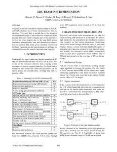
requirements summarised in Table 1. PSS7, soon to be assembled, will be a semi fmal version of the beam
dump switch, composed of 2 PSS6 gaps in series with one common gas reservoir. It shall in principle fulfil all requirements of Table 1. The fmal number of gaps will depend on the results of PSS7. Fig. 1 shows a
CHICANE INSULATOR AN ODE
CATHODE BIAS ELECTRODE
FE TRIGGER DISK
GAS RESERVOIR
achievable with a modified GTO structure. This has
encouraged us to pursue the development of a fast,
Fig. 1 Schematic section through PSS6 OCR Output
OCR OutputOCR OutputIf during repetitive pulsing the needles grow, their tips are probably molten-off by the discharge and fall into the hollow anode or onto the grid electrode in
A more detailed study of the prefire discharges reveals that the phenomenon has at least 2
the hollow cathode, provided the tube is mounted vertically. In these places the erosion products do not
close to the Paschen curve, the natural breakdown
do much harm. A horizontal mounting of the tubes is however probably precluded. Eroded particles would then be deposited in the main anode/cathode gap
during the high power spark, when the severe thermal and mechanical shocks create points of high electrical
causing probably a strong reduction in withstand voltage. The eroded material has to a large extent the shape of perfect spheres with a diameter of several
leads mainly to discharges on the large chicane areas
different sources. It is either caused by operating too level of a gaseous switch, or by electrode damage
field stress and electron emission. The former cause
and the "triple point" zone. This fact can be clearly
rapid solidification. The large needle size has led us to discard the
observed during the first conditioning of a switch, when nearly all prefire flashes can be seen through the semi transparent alumina insulator. This cause can be eliminated by using several gaps in series thus
costly and difficult to machine W/Re alloy as electrode material whose reported ine grain size can not be exploited in the presence of the large erosion
working far below the Paschen border. The latter cause can be eliminated by frequent reconditioning of the switch during the pulse test. In
needles.
this case prefiring should occur on the electrode ring gap near the axis. This assumption is supported by the observation that prefire flashes can only rarely be seen through the insulator when conditioning during a pulse test because most of the discharges are hidden behind
tenths of a millimetre, probably formed during very
Erosion in PSS5 was less uniform and
concentrated on one spot, most likely due to an unidentified stress point. This behaviour is however not considered as characteristic.
the long metallic chicanes. Preiiring Outlook
With PSS’s 4 and 5 the rate of untriggered discharges was about 1% and the repetition time could not be lowered to less than 17 s in order not to
provoke spurious pref`1ring. At 20 kV DC the prefire rate was about once per 3 to 5 hours.
With PSS6 an improvement of the prefire rate of more than 2 orders of magnitude has been
observed. In the pulsed mode 2 pretire discharges were observed during a life test of 5x10⁴ pulses at a repetition time decreased to 10 s and a voltage increased to 22 kV. During overnight and weekend DC tests a voltage of 27 kV could be held over
repeated periods of 15 h and 65 h respectively for a total time of more than 500 h without any preiiring. The improved performances are attributed on the one hand to the improved general mounting conditions (high temperature bake out of all materials prior- to assembly, clean room assembly, improved in situ bake out of switch and gas feeder lines, liquid nitrogen trap for gas filling, addition of a sputter ion pump that lowered the pressure after bake out to less than IO'? Torr). Also the increased diameter of the central
electrode disk contributes probably to the improved pulsed mode performance at higher repetition rate. A new conditioning method certainly helped to obtain the excellent DC voltage holding. Conditioning is now done by triggering the switch with 1 pps repetition rate from a 5 nF capacitor whose voltage is gradually increased up to 35 kV.
A fiuther analysis of the operation mode of the LHC and the reliability requirements of the beam dumping system have shown that repeated PSS conditioning would be useful and is compatible with LHC operation. In fact, before each filling of the LHC with protons a checklist-type program must be scheduled that controls the correct functioning of all vital elements of the beam dumping system. Of prime importance is here the voltage holding of the 24 power switches. It is therefore intended to check before each
fill the withstand voltage by means of an automatic test and conditioning program. Ample time is available for these tests, when the current of the
superconducting magnets is slowly lowered after the physics run to its injection level. The conditioning program foreseen will pulse each gap of the PSS separately at high repetition rate and low current from a power supply whose voltage is increased within about 100 s up to 35 kV. The power is fed to the PSS gaps by means of a set of computer controlled high voltage relays. This method has also the important additional advantage of being able to determine precisely after years of operation the reliability state of a switch.
Originally it was considered necessary to equip PSS7 with 3 gaps in order to fulfil the stringent reliability requirements conceming prefiring. The important performance increase of PSS6 has now led OCR Output
us to believe that a 2-gap version may be sufficient. The maximum voltage per gap is then 17.5 kV whereas the long term withstand voltage measured in our experiments is 27 kV. The resulting safety factor of more than 50% is considered sufficient to guaranty a trouble free operation of the 24 switches of the LHC beam dumping system.
[3]
1989.
[4]
Acknowledzcment
We would like to thank our colleges J.L. Bretin, R. Chappuis, E. Carlier, S. Long and J.P. Pianfetti for their help at various stages in the development program.
H. Gundel, H. Handerek, H. Riege and E.J.N. Wilson, "Copious electron emission from PLZT ceramics with a High Zirconium Concentration", Ferroelectrics, vol. 100, p.1,
L. Courtois, P. Faure, H. Handerek, H. Riege and G.H. Schroder, "Development of High Power Switches for the LHC Beam Dumping Pulser" in Proc. Third European Particle Accelerator Conf. , Berlin, 1992. Ed. Frontiers,
1992, p. 1597. [5]
T. Mehr, J. Christiansen, K. Frank, A. Gortler,
M. Stetter and R. Tkotz, "1nvestigations about Triggering of Coaxial Multi—channel Pseudospark Switches" in IEEE Trans. on
References
[1] G.H. Schroder and E.B. Vossenberg, "A Prototype High-Power Pulse Generator for the Beam Abort System of CERN’s Proposed 16
Plasma Science, Vol. 22 No 1, Febr.1994, p. 78.
TeV Collider LHC" in Proc. l9"‘ Pulse Power
Modulator Symp., San Diego 1990, p.104. [2] J. Bonthond, L. Ducimetiére, M. Evans, E.B.
Vossenberg, F. Wakeman, R. Youdan, “High Current, High di/dt Switching with Optimised GTO Thyrist0rs", this symposium
[6]
P. Benin, L. Courtois, P. Faure, H. Handerek,
H. Riege, K. Schmidt and G.H. Schroder, High Power Gas Switches Triggered by Ferroelectrically Generated Electron Beams" in Proc. of the 9"‘ Int. Pulsed Power Conf.,
Albuquerque 1993.