Helmut Brech, Thomas Grave, Thomas Simlinger, and Siegfried Selberherr, Fellow, IEEE. Abstractâ Measurements and simulations of three different.
1822
IEEE TRANSACTIONS ON ELECTRON DEVICES, VOL. 44, NO. 11, NOVEMBER 1997
Optimization of Pseudomorphic HEMT’s Supported by Numerical Simulations Helmut Brech, Thomas Grave, Thomas Simlinger, and Siegfried Selberherr, Fellow, IEEE
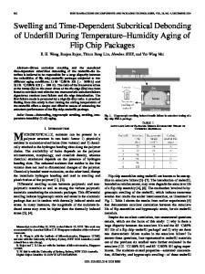
Abstract— Measurements and simulations of three different pseudomorphic high electron mobility transistors (PHEMT’s) are presented. The PHEMT’s possess the same epitaxial structure but different geometrical properties. For the simulations, the generic device simulator MINIMOS-NT is employed. This simulator is not restricted to planar device surfaces but is able to model complex surface topologies including the effect of passivating dielectric layers. Mixed hydrodynamic and drift-diffusion simulations are demonstrated. They include the DC characteristics as well as the bias-dependent gate capacitances. Thus, biasdependent current-gain cutoff frequencies fT can be calculated. The results compare very well with the values obtained by small-signal parameter extractions from S -parameter measurements. Although a single consistent set of parameters is used for the simulations of all three devices, their characteristics are reproduced with an accuracy to our knowledge not reported before. Therefore, the DC and RF properties of PHEMT’s with geometries significantly different from the measured devices can be reliably predicted. Fig. 1. Schematic cross section of the simulated HEMT’s.
I. INTRODUCTION
P
SEUDOMORPHIC high electron mobility transistors (PHEMT’s) on Gallium-Arsenide (GaAs) substrate are now widely used for low noise and high power applications in the microwave and millimeter wave frequency ranges. Although still new record values of extrinsic transconductance and current-gain cutoff frequency are reported 1070 mS/mm and 220 GHz, for instance ( [1]), reliability and reproducibility of the process technology are becoming the key issues for the realization of cheap large-volume production. An optimized device design can reduce the technological effort, increase the yield, and, thus reduce the unit cost of the MMIC’s. To achieve this optimum design, an exact device simulation can substantially support the technological development. Today, most simulators are not able to simulate complicated heterostructure devices with an accuracy sufficient to still predict their performance even if the geometry is significantly changed [2]. This is because parameters of major models such as the electron transport or the electrical contact model to the channel [3] have to be fitted to the measurements individually for each device. In the literature, no simulations have been yet published which treat different devices with a single consistent Manuscript received January 28, 1997. The review of this paper was arranged by Editor W. Weber. H. Brech and T. Grave are with Siemens Corporate Technology, M¨unchen D-81739, Germany. T. Simlinger and S. Selberherr are with the Institute for Microelectronics, TU Vienna, Vienna A-1040, Austria. Publisher Item Identifier S 0018-9383(97)07721-6.
set of parameters. However, this is a major requirement for reliable results. Here, measurements and simulations of three PHEMT’s for low-noise applications are presented. The devices differ with respect to their geometries but employ the same epitaxial structure. The program MINIMOS-NT used for the simulations has been described before [5]. In the present paper, the emphasis is on a detailed demonstration of optimization capabilities for HEMT’s. Details of the simulation are given in the next section. A description of the devices studied follows, and the expected impact of the different geometries on their properties is explained. After a discussion of the quality of the simulations, MINIMOS-NT is used to forecast the performances of devices not fabricated yet. II. SIMULATION The characteristics of a PHEMT are determined by the epitaxially grown structure and by the geometry defined by the manufacturing process. In PHEMT’s, the electron channel is created by a semiconductor layer with narrow bandgap and high carrier mobility sandwiched between semiconductors with higher bandgaps. Fig. 1 shows a schematic view of the transistor investigated in this paper. In the simulated devices, the source and drain contacts are placed on top of the cap layer, similar to the real device. To obtain an exact reproduction of the transfer characteristics, the channel must not be contacted by the source and drain
0018–9383/97$10.00 1997 IEEE
BRECH et al.: OPTIMIZATION OF PSEUDOMORPHIC HEMT’S
TABLE I PARAMETERS USED FOR SIMULATION
TABLE II TRANSPORT PARAMETERS
AND
DOPING
metals directly, as it has been the case in most published PHEMT simulations. Thus, all semiconductor interfaces that are crossed by the electrons between source and drain are realistically included in the calculations [3]. Abrupt interfaces are introduced by splitting the device into a number of different regions where different transport models and parameters can be applied. These regions are connected to each other by an interface model which describes the electron transport across the heterojunctions. Details of both bulk and interface models have been given earlier [5]. In the PHEMT channel, a hydrodynamic transport model is applied which includes the effects of velocity overshoot and real space transfer for the interface model. This model is essential for a realistic simulation of current saturation in the transfer characteristics [3] and geometry variations such as changes in gate length and . In all regions outside the channel, a driftrecess length diffusion model is applied. By this means, the computation time consuming hydrodynamic calculation is restricted to the most important region of the device [3]–[5]. In the simulations of the geometrically different PHEMT’s, always the same set of parameters has been used. The most important of them are shown in Tables I and II. A more complete overview over the simulation parameters is given in [5]. III. PHEMT DEVICE STRUCTURE AND KEY PARAMETERS The epitaxial structure common to all devices studied is shown in Fig. 1. From bottom to top the structure consists in a GaAs buffer on a S.I. GaAs substrate followed by a 12 nm In Ga As channel layer, a 3 nm undoped Al Ga As spacer layer, a 15 nm Al Ga As layer with an active doping of 3.5 10 cm and a 7 nm undoped Al Ga As Schottky barrier layer. The top layer is formed by a highly doped GaAs cap to facilitate the formation of the source and drain ohmic contacts. The different geometries of the three investigated PHEMT’s A, B, and C are given in Table III. Before presenting the results of the small-signal parameter extractions and the simulations, we will qualitatively discuss with simple arguments the differences that must be expected between the properties of devices A, B, and C. One major figure of merit of a HEMT is its maximum . Among the parameters given in transconductance
1823
TABLE III GEOMETRY PARAMETERS OF THE SIMULATED HEMT’S
Table III, the most important one for is the gate-to. The critical technological step which channel separation determines the magnitude of is the gate recess. In the recess region, it is intended to remove the GaAs cap layer completely but to leave the AlGaAs Schottky barrier intact. In practice, this etching can only be performed with finite selectivity, and the effective recess depth can vary a few nanometers across the wafer or from one processing run to another. Therefore, from the small deviations in the order of 2 nm of the actual values given in Table III must be considered to be realistic. and from their nominal Deviations of the parameters values in Table III are also technologically inevitable but do as . The intrinsic not have as large an influence on (i.e., for vanishing source resistance ) of a PHEMT is given by [6] (1)
, , and are the permittivity of the semiconHere, , ductor, equilibrium electron concentration, low field electron mobility, and saturation velocity in the channel, respectively, is the distance between the channel/barrier hetand erointerface and the maximum of the electron probability distribution in the channel. Equation (1) demonstrates that is basically dependent on . This means that on the effect of the same absolute variation of increases for decreasing . Today, PHEMT’s of interest have gate lengths below a quar250 nm, inspection of (1) ter micrometer. For constant is nearly independent of if is higher reveals that than 3000 cm /Vs which is usually the case in PHEMT’s. depends On the other hand, (1) also states that for below about 200 nm, and that it is only weakly on in the range 500 nm. This reduced proportionally to as the most important technological parameter establishes for the transconductance of the PHEMT’s investigated here. must be expected Thus, only a small difference of between devices A and B of Table III, but a slightly higher as value for device C due to a significantly shorter is reduced. The gate length variations are not likely to have a but will have other consequences. The large impact on short of HEMT’s A and C will lead to a small gate-source and, thus, to a higher compared to HEMT capacitance B. However, further consequences of the parameter variations in Table III cannot be easily estimated quantitatively. Such consequences are the increase of the output conductance (and the decrease of the voltage gain ) that is expected or . A small will cause a small with a decrease of , but unfortunately, a large gate-drain capacitance
1824
IEEE TRANSACTIONS ON ELECTRON DEVICES, VOL. 44, NO. 11, NOVEMBER 1997
active dopant atoms and a constant interface charge density between the passivation and the semiconductor [10]. The data given in Table III lead to the best simultaneous fit to the DC measurements of threshold voltage , drain current and , and are well within their respective transconductance ranges of uncertainty. A. Comparison of HEMT’s A and B
Fig. 2. Small-signal equivalent circuit used for parameter extraction.
undesirable for high and high power-gain cutoff frequency . Numerical simulation is requested for the calculation of these effects. IV. SMALL-SIGNAL PARAMETER EXTRACTION -parameter measurements were performed on HEMT A and B between 1 and 40 GHz. Contact pads and contacting microstrip lines are parasitic elements that are included in the measured results. The extraction of the intrinsic small, , and was performed for signal parameters HEMT A according to [7], using the equivalent circuit shown in Fig. 2. This circuit takes the parasitic elements into account and and the inducby introducing the capacitances , , and . Thereby it is possible to separate the tances elements of the HEMT from the contacting network. In the MINIMOS-NT simulations the total extrinsic gate is determined by the quasistatic approximation capacitance (2) being the total charge on the gate metal surface at with a given DC bias point. V. SIMULATIONS
AND
MEASUREMENTS
All DC and RF measurements were performed on HEMT’s with a gate width of 4 40 160 m. First, the simulation of HEMT A was fitted to the measurements in the following way. For the low field mobility in the InGaAs channel, the value obtained from Hall measurements of an equivalent layer structure was adopted. The InGaAs saturation velocity was treated as a fitting parameter under the assumption that the velocity yielded by a HEMT delay time analysis is subject to and an error of about 20% [8]. The actually used values of for InGaAs channel, AlGaAs supply, and GaAs substrate, buffer, and cap are listed in Table II. The saturation velocity assumed for GaAs is unrealistically low. This was deliberately chosen to compensate the overestimation of the buffer current which is a well known result of most simulations. As a physical reason, it is discussed that the carriers might be better confined to the channel due to quantization effects than assumed in the bulk model of the simulation [9]. However, the buffer current plays a minor role at the bias points of interest. Therefore, the method chosen to reduce the buffer current does not have a significant impact on the results of the simulation. , the concentration of Other main fitting parameters are
Measured and simulated transfer characteristics of HEMT’s A and B are shown in Fig. 3. Though the parameter fit procedure described above was only applied to HEMT A, also HEMT B is simulated precisely. Both measurements and simulations show that the drain current of HEMT A ( 170 nm) is larger than the current of HEMT B ( 240 nm) by about 40 mA/mm. As can be seen in Fig. 4, also the maximum transconductance of HEMT A is superior to that of HEMT B by approximately 20 mS/mm, again measured as well as simulated. These results reflect the faster carrier transport due to the shorter gate of HEMT A. If the larger of HEMT A would not be caused by accelerated smaller than estimated in transport but by a distance Table III, one would expect it to be correlated with a smaller instead of a larger one. This comparison with experiment provides evidence that MINIMOS-NT is able to model and of both HEMT’s in a consistent and realistic manner. However, there is also one small detail shown in Fig. 4 in which simulation and measurement do not agree completely: for which is measured the gate-source voltage for HEMT B is slightly more negative than the simulated one. The reason for this behavior is not clear. As the two HEMT’s were not fabricated in the same lot, small differences in the semiconductor passivation interface states could occur. On the other hand, the experimental observation that the transconductance of HEMT A decreases more rapidly with than that of HEMT B is accurately increasing positive reproduced by the simulation. The physical origin of this effect is the stronger real space transfer of electrons from the channel into the low-mobility barrier layer [3] in the device with the shorter gate (HEMT A). The increase of real space transfer in short channel devices is also leading to a higher output conductance. This will be discussed in Section VI. of Fig. 5 shows the simulated gate capacitances below pinchoff (i.e., 0.9 HEMT’s A and B. For consists of the gate-drain capacitance and V), parasitic contributions including the fringe capacitances. These values are very similar for both transistors. When increases, the longer gate of HEMT B manifests itself in compared to HEMT A. For HEMT a stronger increase 520 fF, and for HEMT A, 350 fF. The B, 520/350 1.48 is close to the ratio of ratio 240/170 1.41, as expected. the gate lengths B. Comparison of HEMT’s A and C Initially, HEMT C was assumed to possess the same dis25 nm as HEMT A but only a slightly longer tance 190 nm and a shorter 60 nm. When these values are used in the simulation, this results in a too negative
BRECH et al.: OPTIMIZATION OF PSEUDOMORPHIC HEMT’S
1825
Fig. 3. Measured and simulated transfer characteristics of HEMT A and B at VDS 2.0 V.
Fig. 6. Measured (bold line without symbols) and simulated transfer characteristics of HEMT C with the nominal dgc (circles) and dgc 1.7 nm (triangles) at VDS 2.0 V.
Fig. 4. Measured and simulated transconductance of HEMT A and B at VDS 2.0 V.
Fig. 7. Measured (bold line without symbols) and simulated transconductance of HEMT C with the nominal dgc (circles) and dgc 1.7 nm (triangles) at VDS 2.0 V.
=
=
Fig. 5. Simulated
CG of HEMT’s A and B at VDS = 2.0 V.
value of and an overestimated , as can be seen in by 1.7 nm leads to Fig. 6. However, a reduction of perfect coincidence of measured and simulated curves, as it of such small size is also shown in Fig. 6. Variations of
0
=
=
0
can easily occur in different technology runs. The agreement between measurement and simulation is even more evident for the transconductance shown in Fig. 7. Both the peak value 580 mS/mm and its occurrence at 0V are simulated very well. We now return to the initial simulation of HEMT C which is equal to the was performed under the assumption that 25 nm). When this simulation of value of HEMT A ( a “hypothetical” HEMT C (circles in Fig. 7) is compared to the simulation of HEMT A in Fig. 4, it is found that the that is about 25 mS/mm hypothetical device has a larger than the value of HEMT A though its gate is 20 which is 75 nm longer. This must be a consequence of nm shorter and obviously overcompensates the small effect of the slightly longer gate. From the previous comparison ), we can between HEMT’s A and B (which share the same estimate that an increase of 20 nm only causes a negligible decrease of about 5 mS/mm. This independently confirms the conclusion drawn above: the reduction of had a stronger impact on the transconductance of HEMT C than the slightly longer .
1826
IEEE TRANSACTIONS ON ELECTRON DEVICES, VOL. 44, NO. 11, NOVEMBER 1997
Fig. 8. Simulated VDS 2.0 V.
=
CG
of HEMT A (squares) and HEMT C (circles) at
A drawback of the shrinkage of is the increase of . This can be seen in Fig. 8 which shows the simulated gate of HEMT’s A and C. For HEMT C, the capacitance ( ) is shifted toward higher values by whole function about 130 fF/mm as compared to HEMT A. As the shift is already completely present in the pinchoff region it can be entirely attributed to the increased coupling between the gate and drain contacts.
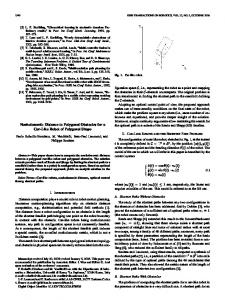
Fig. 9. Measured (bold line without symbols) and calculated simulated (squares) and extracted (triangles) CG and gm at VDS
fT
with
= 2.0 V.
TABLE IV PARASITIC SMALL-SIGNAL PARAMETERS FROM PARAMETER EXTRACTION OF HEMT A WTH A GATE WIDTH OF 160 �m
VI. DEVICE OPTIMIZATION An important figure of merit of a HEMT is the current-gain cutoff frequency approximately given by (3) For the case of HEMT A, Fig. 9 shows a comparison of the ( ) determined in three different ways: functions 1) measured (i.e., obtained by -parameter measurements); and 2) calculated with (3) where were obtained from extractions using the small-signal equivalent network shown in Fig. 2; 3) obtained from simulations also using (3) with and . The last two cases offer the possibility to determine the device performances excluding the contacting network which calculated is necessary for circuit design. As shown, the from extracted and simulated data agree reasonably well especially with respect to their maxima. The measured value is about 13 GHz lower than the calculated ones mainly due to the presence of the parasitic elements indicated in Fig. 2. The values of the small-signal circuit elements for HEMT A which are considered to be not bias dependent are given in Table IV. In the following we want to examine the influence of the and on the magnitude of geometrical parameters simulated according to (3). The capacitance entering the and , but equation is greatly influenced not only by also by the shape of the gate metal cross section (imagine, for instance, the case of a T-gate) and the dielectric constant of the passivation material that fills the space between
metal structure and semiconductor surface. Our simulator is able to take all these effects of surface topology fully into account. On the other hand, only in simulation it is possible to analyze the hypothetical case that the gate does not interact capacitively with the surrounding semiconductor surfaces or with the neighboring ohmic contacts, i.e., a non passivated device with an infinitesimally thin gate metal but negligible 0 and gate resistance. This can be achieved by choosing leads to the determination of the theoretical maximum of for given and . A. Reduction of the Gate Length is reduced, will increase, but a simultaneous When must and undesirable increase of the output conductance be expected. In Fig. 10 the simulated parameter (at the bias 2 V, 0 V) is shown as a function of point and compared to the experimental DC values of HEMT’s A and B which differ only with respect to but not in any other geometrical dimensions. The simulation is able to reproduce realistically. is only As described in Section III, the increase of is reduced. The capacitance is nearly small when is only independent of . The gate-source capacitance partly dependent on : fringe and other parasitic contributions are independent of , only the part due to the gate contact area is length dependent. Therefore, the improvement of which can be achieved by a reduction of , depends on the
BRECH et al.: OPTIMIZATION OF PSEUDOMORPHIC HEMT’S
1827
Fig. 10. Measured (filled symbols) and simulated (open symbols) output conductance go versus the gate length at the bias point VGS 0.2 V and VDS 2.0 V.
=
=
=
Fig. 12. Simulated fT versus lrecess for a passivated HEMT with "r 7 (filled symbols) and "r 0 (open symbols) at VGS 0.2 V and VDS 2.0 V.
=
=
=
device of the general structure of HEMT A must be either supplied with a gate length below 100 nm, or the gate length is left as large as in HEMT B (240 nm) but no passivation is allowed at all. The case of an unpassivated device in air with 1 is close to the idealized case 0 plotted in Fig. 11. The two curves in Fig. 11 are calculated under the assumption of a constant interface charge density which is certainly an idealization when the unpassivated case is considered. B. Reduction of the Recess Length is increased when As demonstrated in Section V, is reduced. The reason is a decrease of the ohmic resistance is expected to depend in the current path. Therefore, . We have found that the dependence roughly linearly on on can be modeled by of Fig. 11. Measured (filled squares) and simulated fT versus lg for a passivated HEMT with "r 7 (filled circles) and "r 0 (open circles) at VGS 0.2 V and VDS 2.0 V.
=
=
=
=
relative contribution of the parasitic (i.e., constant) part of the . The dependence of capacitance to the gate capacitance on is shown in Fig. 11 for two examples: the limiting case of 0 where the contribution of parasitics is reduced to the inevitable fringe capacitances at the gate edge, and the 7 (a silicon case of the presence of a medium with nitride passivation layer, for instance) which fills the space between the T-gate overhang and the semiconductor surface in the manner sketched in Fig. 1. The measured values in Fig. 11 (which are taken from HEMT’s A and B) are even below the ones calculated with complete T-gate structure and passivation nitride due to the presence of parasitic pad capacitances as discussed before. Fig. 11 demonstrates clearly that the improvement of achieved by a reduction of depends strongly on the relative contribution of parasitic capacitive couplings to the total gate in the presence of passivation capacitance. The reduction of layers has been experimentally observed for instance by Wu of 100 GHz, a fully passivated et al. [11]. To obtain an
(4) and are constants. The simulated dependence of is plotted in Fig. 12. In the hypothetical situation 0, there is almost no dependence of on , and increases monotonously with decreasing due to the . For the case that the gate and the improvement of adjacent device surfaces are encapsulated by a dielectric with 7, the decrease of on the left hand side of the 90 nm is caused by the rapidly increasing maximum at . If a device passivation with a dielectric constant 7 would be higher for would be available, it is evident that 7 and the optimum of would be shifted toward any smaller values. where on
VII. CONCLUSION Simulations and measurements of three PHEMT’s with the same epitaxial structure but different geometries are presented. The results of the simulation were fitted to experimental results obtained from one of the three devices by adjustment of the most important simulation parameters well within realistic ranges. With the same set of parameters, the remaining two
1828
IEEE TRANSACTIONS ON ELECTRON DEVICES, VOL. 44, NO. 11, NOVEMBER 1997
devices were also simulated. The calculated and measured DC characteristics of all three devices agree extremely well. For instance, this enables us to trace differences of the gate recess depths of the investigated HEMT’s with an accuracy in the range of 1 nm. The calculated bias dependent current-gain cutoff frequency also agrees well with the values obtained from small-signal parameter extractions. This capability to model different HEMT’s realistically is the basis for substantial predictions on the effect of geometrical variations that go beyond the ones already realized experimentally. These predictions include DC as well as RF properties. This qualifies simulation as a valuable tool for device optimization which can significantly reduce the number of technological runs inevitable for this purpose.
[5]
[6] [7] [8] [9] [10] [11]
ACKNOWLEDGMENT The authors would like to thank A. Stemmer and H. Tischer for the DC and RF measurements of the HEMT’s. The epitaxial layers used for PHEMT fabrication were MBEgrown by the Walter Schottky Institute, Technical University of M¨unich.
and H. van Kranenburg, Eds. Gif-sur-Yvette Cedex, France: Editions Frontiers, 1995, pp. 83–86. T. Simlinger, H. Brech, T. Grave, and S. Selberherr, “Simulation of submicron double-heterojunction high electron mobility transistors with MINIMOS-NT,” IEEE Trans. Electron Devices, vol. 44, pp. 700–707, May 1997. M. Shur, GaAs Devices and Circuits. New York: Plenum, 1987, p. 565. M. Berroth and R. Bosch, “High-frequency equivalent circuit of GaAs FET’s for large-signal applications,” IEEE Trans. Microwave Theory Tech., vol. 39, pp. 47–50, Feb. 1991. Y. Kwon and D. Pavlidis, “Delay time analysis of submicron InP-based HEMT’s,” IEEE Trans. Electron Devices, vol. 43, pp. 228–237, Feb. 1996. C. Moglestue, “A Monte Carlo particle simulation of quantum transport in MODFET’s,” in Proc. 9th III–V Semiconductor Device Simulation Workshop, Heeze, The Netherlands, May 9/10, 1996. R. Anholt, “Dependence of GaAs MESFET fringe capacitances on fabrication technologies,” Solid-State Electron., vol. 34, no. 5, pp. 515–520, 1991. C. S. Wu, C. K. Pao, W. Yau, Z. Bardai, D. Bosch, C. Seashore, and M. Gawronski, “Pseudomorphic HEMT manufacturing technology for multifunktional Ka-Band MMIC applications,” IEEE Trans. Microwave Theory Tech., vol. 43, no. 2, Feb. 1995.
Helmut Brech, for a photograph and biography, see p. 707 of the May 1997 issue of this TRANSACTIONS.
REFERENCES [1] F. Diette, D. Langrez, J. L. Cordron, E. Delos, D. Theron, and G. Salmer, “1510 mS/mm 0.1 �m gate length pseudomorphic HEMT’s with intrinsic current gain cutoff frequency of 220 GHz,” Electron. Lett. vol. 32, no. 9, pp. 848–850, Apr. 1996. [2] R. Anholt, Electrical and Thermal Characterization of MESFET’s, HEMT’s, and HBT’s. Boston, MA: Artech House, 1995, p. 25. [3] H. Brech, T. Simlinger, T. Grave, and S. Selberherr, “Current transport in double heterojunction HEMT’s,” in Proc. ESSDERC’96—26th Euro. Solid State Device Res. Conf., G. Baccarani and M. Rudan, Eds. Gifsur-Yvette Cedex, France: Editions Frontiers, 1996, pp. 873–876. [4] T. Simlinger, H. Kosina, M. Rottinger, and S. Selberherr, “MINIMOSNT: A generic simulator for complex semiconductor devices,” in Proc. ESSDERC’95—25th Euro. Solid State Device Res. Conf., H. de Graaf
Thomas Grave, for a photograph and biography, see p. 707 of the May 1997 issue of this TRANSACTIONS.
Thomas Simlinger, for a photograph and biography, see p. 707 of the May 1997 issue of this TRANSACTIONS.
Siegfried Selberherr (M’79–SM’84–F’93), for a photograph and biography, see p. 707 of the May 1997 issue of this TRANSACTIONS.