Jun 22, 1998 - Aramco, Exxon, Owens-Corning, Chevron Chemical Co.,. Asahi Glass, Chevron Research and Technology Co., Her- cules, Avery Dennison ...
An Optimal Feedforward Design for Complete PMD. Compensation Up to the Second Order. George Ouyang, Avishay Eyal, Member, IEEE, and Amnon Yariv, ...
back control of cable-suspended robots a lot more challenging than their counterpart ... dimension of the robot; 2) lightweight cables resulting in very safe and.
Authorized licensed use limited to: Danmarks Tekniske Informationscenter. Downloaded on ... Let a coprime factorization of the system Gyu from (1) and a stabi-.
and simulation results reported in literature [12], [14], [20]. The design of Ge profile for different base doping profiles is studied using our analytical model for ...
Chin-Teng Lin*, I-Fang Chung, Li-Wei Ko, Yu-Chieh Chen,. Sheng-Fu Liang, and Jeng-Ren Duann. AbstractâAccidents caused by errors and failures in human ...
We show that for a broad set of beliefs and group characteristics cooperation can appear ... Although there are no simple solutions to social dilemmas, studying them sheds ... thus more likely to cooperate the greater the observed level of cooperatio
to predict the estimators mean square error (mse) threshold effect. A tractable and ... bound on the variance of any unbiased estimator. Unfortunately, most.
high-gain gyrotron traveling wave amplifier (gyro-TWT) are .... is required for high-power generation. ...... microwave/millimeter wave generation, large-area.
AbstractâMultiproject wafer (MPW) production cost are sensitive to how the ..... cost, exposure cost per wafer, and field-size independent wafer cost per wafer ...
segments are projected onto depth segments so that video objects ...... [20] M. Mills, J. Cohen, and Y. Y. Wong, âA magnifier tool for video data,â in Proc.
AbstractâWe propose a framework to model, analyze and design three-dimensional (3-D) imaging systems. A system engi- neering approach is adopted which ...
AbstractâThe problem of observer design for Lipschitz nonlinear sys- ...... [20] G. Schreier, J. Ragot, R. J. Patton, and P. M. Frank, âObserver design for a class of ...
JESD22-A120, 2001. [10] C. H. Shen and G. S. Springer, âMoisture absorption and desorption of composite materials,â J. Compos. Mater., vol. 10, no. 2, pp. 2â20 ...
[6] T. Lane and L. P. Kaelbling, âNearly deterministic abstractions of. Markov decision ... [8] E. L. Lawler, J. K. Lenstra, A. H. G. Rinooy Kan, and D. B. Shumoys,. The Traveling .... line D0 of both lines, the cusps lie on D+ and D0, and at each
... Leung, C. C. Yu,. R. J. Tsai, C. K. Lee, T. C. Lu, and S. C. Wang, Senior Member, IEEE ... Yat-Sen University, Kaohsiung 80424, Taiwan, R.O.C.. Digital Object ...
Performance comparisons of the gradient descent and the MNM using three potential models: generalized Gaussian potential function, parabolic potential.
May 25, 1998 - ci, illustrated in Figs. 1â4, respectively. (i) Strong majority representation: The CBM of. GaAlAs and GaInAs.âFigure 1 shows c. 2. CBM r and.
1475â1476,. 1995. [11] C. Bintjas, N. Pleros, K. Yiannopoulos, G. Theophilopoulos, M. Ka- lyvas, H. Avramopoulos, and G. Guekos, âAll-optical packet address.
variable and the frame rate by integer ... the frame rate, and the interval between two frames is the ... millimeters per second which corresponds to frame rates in.
May 12, 1998 - H. Lefort,1 S. Kandri-Rody,1,* N. Pauwels,1 J. C. Potier,1 J. Proust,1 J. C. Putaux,1 .... (effective deuteron energy, neutron angular distribution.
[2] D. J. Ward, A. F. Blackwell, and D. J. C. MacKay, âDASHERâA data entry interface ... J. Adam Wilson, Elizabeth A. Felton, P. Charles Garell,. Gerwin Schalk ...
The work of A. Eyal was supported by the Eshkol Fellowship of the same min- istry. A. Eyal was with the Department of Interdisciplinary Studies, Faculty of En-.
504
JOURNAL OF LIGHTWAVE TECHNOLOGY, VOL. 19, NO. 4, APRIL 2001
Polarization Mode Dispersion in Radio-Frequency Interferometric Embedded Fiber-Optic Sensors A. Eyal, Member, IEEE, O. Dimenstein, M. Tur, Fellow, IEEE, M. Zaidman, A. Green, and S. Gali
Abstract—The effect of fiber birefringence on the propagation delay in an embedded fiber-optic strain sensor is studied. The polarization characteristics of the sensor are described in terms of polarization mode dispersion through the principal states of polarization and their differential group delay. Using these descriptors, an analytical expression for the response of the sensor for an arbitrary input state of polarization is given and experimentally verified. It is found that the differential group delay, as well as the input and output principal states of polarization, vary when the embedded fiber is strained, leading to fluctuations in the sensor output. The use of high birefringence fibers and different embedding geometries is examined as a means for reducing the polarization dependency of the sensor. Index Terms—Birefringence, embedded fiber-optic sensors, intelligent structures, optical fiber dispersion, optical fiber polarization, polarization mode dispersion.
I. INTRODUCTION
E
MBEDDED fiber-optic sensors are among the most promising technologies available for monitoring the mechanical properties of structures in real time. In many types of structures, made of various materials, an optical fiber may be embedded with little effect on the mechanical properties of the structure [1]. In contrast, the embedding process may considerably affect the optical properties of the fiber. In particular, anisotropic stresses may introduce significant birefringence into the otherwise low birefringence fiber. In many applications, the light through the sensor is modulated and information propagates with the light group velocity. In these cases, the presence of birefringence may lead to polarization mode dispersion (PMD). PMD refers to the dependence of the group velocity of light on its state of polarization [2]. The phenomenon has been extensively studied in recent years, since it limits the bandwidth of fiber-optic communication systems. To the best of our knowledge, the effect of PMD on fiber-optic sensors has never been explicitly treated in the literature. In Manuscript received May 15, 2000; revised December 27, 2000. This research was supported in part by the Israeli Ministry of Science and Technology. The work of A. Eyal was supported by the Eshkol Fellowship of the same ministry. A. Eyal was with the Department of Interdisciplinary Studies, Faculty of Engineering, Tel-Aviv University, Tel Aviv 69978 Israel. He is now with the Department of Applied Physics, California Institute of Technology, Pasadena, CA 91125 USA (e-mail: [email protected]). O. Dimenstein and M. Tur are with the Department of Interdisciplinary Studies, Faculty of Engineering, Tel-Aviv University, Tel Aviv 69978 Israel (e-mail: [email protected]). M. Zaidman, A. Green, and S. Gali are with Israel Aircraft Industries, Lod, Israel. Publisher Item Identifier S 0733-8724(01)02756-6.
general, the birefringence in embedded fiber-optic sensors is not homogeneous, but rather randomly varies along the fiber. The description of PMD in this type of medium is commonly done by specifying two states of polarization that correspond to the overall minimum and maximum group delays and by the difference between the appropriate group delays. These polarization states are called the principal states of polarization (PSPs), and the difference between their group delays is called the differential group delay (DGD) [2]. In a recent paper [3], we studied the effect of birefringence on the performance of a fiber-optic radio-frequency (RF) interferometeric strain sensor. This sensor monitors the average strain in an embedded optical fiber by measuring the group delay of a modulated optical carrier that is transmitted through the fiber [4]. The presence of birefringence in the embedded part of the sensor leads to fluctuations in its response. In this paper, we use the PSPs and their DGD to quantitatively describe these polarization-induced fluctuations. In the first part of this paper, we describe a theoretical model that gives an analytical relation among the PSPs, their DGD, and the input SOP to the fluctuations in the response. Using a novel measurement setup, the PSPs of the embedded fiber and their DGD are measured as a function of the strain. In parallel, the related variations in the group delay are determined using RF interferometery. Our results show that when the fiber is strained its DGD, its input and output PSPs change. These changes are directly related to the polarization-induced fluctuations and can be used to give an independent estimate of them. Although this work refers to a specific device, the results we obtained are quite general. They show that PMD can significantly affect the performance of embedded fiber sensors and that the PSPs and their DGD are significant in describing these effects. It is important to find ways to reduce the effect of the embedding-induced PMD. We studied two approaches for minimizing the effects of PMD: the use of a high birefringence (HiBi) fiber and a sensor in which there are no bends in the embedded part of the sensing fiber. It was found that the use of an HiBi fiber could not eliminate the polarization-induced fluctuations, since the embedding process has impaired the polarization-preserving properties of the HiBi fiber. By using a sensor in which bends in the embedded part of the fiber were avoided, the fluctuations were significantly reduced. The paper is organized as follows. In Section II, we describe the sensor and develop an analytical expression for the PMDinduced fluctuations in the sensor output. Section III comprises a description of the experimental part of this study in which the PMD-induced fluctuations for different embedded fibers and
EYAL et al.: RADIO-FREQUENCY INTERFEROMETRIC EMBEDDED FIBER-OPTIC SENSORS
505
Fig. 1. A fiber-optic based RF interferometer for strain sensing.
different embedding geometeries were measured. The results of the experiment are described in Section IV. Section V contains a discussion and summary.
The input polarization can be decomposed into a weighted sum of optical fields polarized parallel to the two input PSPs, and (4)
II. THEORY A schematic of a fiber-optic RF interferometer is described in Fig. 1. An optical carrier at frequency , modulated by an RF , is transmitted through an opsignal at frequency tical channel. The optical channel comprises the sensing fiber (SF), being a single mode (SM) or an HiBi fiber, either embedded or free, and standard SM fibers, which lead to/from the SF. The signal is detected and the result is electronically mixed with a reference with the same RF frequency. The signal at the IF output of the mixer is proportional to the cosine of the RF-phase difference between the two arms of the interfer, where is the corresponding difference in ometer: is propagation delay. Before a measurement, performance . Under this “quadrature” conadjusted to obtain dition, the sensitivity of the sensor is at maximum and its output becomes directly proportional to small changes in the propagation delay in the SF, (1) When the optical fiber is strained, the change in is the result of two major effects: the length of the fiber is changed by and the refractive index is changed due to the strain-optic effect . For small deformations, the total change in is given by by [5]
are complex weights. Being a PSP, transformed at where the fiber output to a frequency-independent output polarization , with a frequency-dependent phase and amplitude [2]. The input RF modulated optical field appears at the fiber output with two polarization components parallel to the output PSPs, each carrying an undistorted delayed replica of the modulation information
(5) , , and are, respectively, the transmittances, Here phases, and group delays associated with the PSPs. As was experimentally found, the transmittances were essentially constant within the modulation bandwidth so their value at the carrier frequency was used in (5). Under sinusoidal modulation, having modulation index , the envelope of the electric field is expressed by (6) The detected RF signal at the receiver end is derived from . Substituting (6) the intensity of the optical field into (5), becomes a weighted sum of three delayed versions of the original modulating signal, each with a different delay
(2) is the average strain within the fiber and depends where on the Pockels constants and the Poission ratio of the fiber. Let the RF modulated optical field at the input of the fiber, having an arbitrary polarization, as described by a Jones vector [6] , be expressed by (3) where
describes the RF modulation.
strain
strain
(7)
Equation (7) describes the RF signal at the input to the mixer as a cosinusoidal signal at the RF frequency with an effective delay of , which depends on the length of the SF, the applied is strain, and the birefringence properties of the SF. Here,
506
JOURNAL OF LIGHTWAVE TECHNOLOGY, VOL. 19, NO. 4, APRIL 2001
to be very sensitive to strain since it depends on the optical phase difference between the PSPs. Equation (8) gives a criterion for determining when this effect can be ignored. Its contribution to the variations in the effective delay is insignificant as long as . III. EXPERIMENT
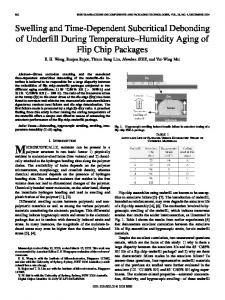
Fig. 2. Phasor diagram for finding .
the projection of one output PSP on the other, is the op. tical phase difference between them, and , the PSPs are mutually orIn the absence of PDL thogonal and the third term in (7) vanishes. Formulas for the polarization-dependent effective delay in the absence of PDL , first appeared in [7], where we assumed that DGD and more recently in [8] and [10], where now the DGD could DGD . Since the DGD measured take any value in our system was always at most a few picoseconds, while the is RF frequency was 2.5 GHz, the condition DGD clearly satisfied. In this case, the polarization-dependent group delay is simply a weighted average of the maximum and minand weights, respectively imum group delays with [7]. Anticipating the possibility of some PDL in our sensor, we in (8), so that the effective now assume that delay in the presence of PDL becomes (Fig. 2) [8]
DGD
(8)
Equation (8) expresses the effective delay of the RF signal as a sum of two terms: 1) , representing the overall delay, including the stress-induced contribution of (2), averaged over the two polarizations; and 2) a polarization-dependent correction of the order of the DGD. Thus, depends on the input state of polarDGD ization (SOP), having a maximum value of and a minimum value of DGD , corresponding to and , respecinput SOPs parallel to tively. For all the other input SOPs, will be vary between and , depending upon the projection of their corresponding output SOP upon the output PSPs. Conversely, for a given SOP but varying PSPs (e.g., in response to applied tensile stresses on may not the sample and, consequently, the embedded SF), respond linearly to the applied strain, as predicted by (2), but will rather show small deviations from linearity, corresponding to the exact value of the second term in (8). Another potential source for deviations from linearity is due to the presence of PDL. The third term in (7), which describes the mixing of the nonorthogonal PSPs in the case where PDL is present, is likely
In order to correlate the measured delay with the polarization properties of the embedded fiber, the experimental setup of Fig. 3 is constructed. This setup can simultaneously measure the effective delay together with the input/output SOPs, the PSPs, and the DGD. A tunable laser around 1550 nm was used to facilitate the measurement of the PSPs and the DGD. After amplification in an erbium-doped fiber amplifier and a polarization controller, the RF modulation ( 2.5 GHz) from an RF signal generator was imparted onto the optical carrier, with modulation , by an LiNbO integrated-optics external moddepth ulator. The light continued into the optical arm of the interferometer, which contained the fiber embedded in a composite sample. Using a polarization synthesizer, the state of polarization (SOP) at the input of the optical channel could be adjusted to any desired condition. The output optical signal from the sensing fiber was then split in a low PDL coupler: half of it was converted into an RF signal by a broadband optical receiver, while the rest was directed into a polarization analyzer to allow a real-time measurement of the output SOP. The RF output was mixed with a replica of the RF modulating signal. Before each set of measurements, the interferometer was calibrated and tuned (through ) to quadrature . From the adjustment of that point onward, the experimental procedure was cyclic. Each cycle comprised three stages. In the first stage, the RF modulation was turned off and the PSPs of the optical channel and their DGD were measured using the complex plane method [11]. In this method, the output SOPs for three arbitrary but known input SOPs are measured at two closely spaced optical frequencies. Using a first-order Riccati differential equation that describes the motion of the output SOP as a function of frequency in the Complex plane, the PSPs and the DGD are estimated. The advantage of this method over the Poincare sphere method is that it is valid in the presence of PDL. Next, the output of the sensor was recorded for three different input SOPs, an arbitrary state , and the input PSPs . Then the strain of the SF was incremicrostrain, as measured by strain mented by gauges attached to the sample. Thus, a strain range of 0–2000 microstrains was covered in ten steps. The fibers we have tested were single-mode or HiBi, either free or embedded in a composite laminated plates. The refraction-index difference between the slow and fast axes of the HiBi fiber was approximately 7.5 10 . All fibers were polyimide coated to provide thermomechanical compatibility with the embedding process. Two plates, having different geometries, were tested. The plates were manufactured using conventional aircraft industry layup, vacuum bag and autoclave cure techniques with process temperatures up to 185 C, and pressures of 7 bars. The plates were made of four plies, with the fibers were embedded between the second and the third plies. An important consideration in the design of the plates was to enable them to
EYAL et al.: RADIO-FREQUENCY INTERFEROMETRIC EMBEDDED FIBER-OPTIC SENSORS
Fig. 3.
507
The experimental setup.
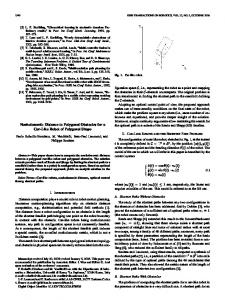
be tightly held by the loading machine without damaging the fibers. The first solution (plate I, Fig. 4) was to let the ends of the embedded fibers exit the plate from one of its sides, leaving the ends of the plate free to be grabbed. It will be seen below that this configuration was very sensitive to polarization-induced fluctuations, apparently due to the fact that part of the embedded fiber is bent. The radius of the bends was roughly 4 mm. The second plate (plate II, Fig. 4) was designed to solve this problem. The embedded part of the fiber is straight, and the fiber is exiting the plate from special holes near the ends of the plate. As shown below, this design was indeed less sensitive to polarization-induced fluctuations. IV. RESULTS To test our experimental setup and processing algorithms, the strain in a free SM fiber was measured (Fig. 5 below) for the three input SOPs: the two input PSPs and an arbitrary SOP. As expected, the sensor showed a linear response with no significant polarization dependency. Quite different behavior is observed in the case of a free HiBi fiber (Fig. 6). Dependence of the sensor response on the input SOP is clearly seen. Since the unstrained sensor was adjusted to zero output (quadrature condition) for the arbitrary SOP, and due to PMD, different input SOPs show nonzero responses at zero applied stress, resulting in vertical shifts of the curves. The size of the shifts, 780 microstrain, corresponds to a DGD of 2 ps in agreement with the specifications of the fiber. In accordance with (8), the upper and lower limits of the sensor output, at any particular stress condition, correspond to the slow PSP and fast PSP, respectively, and the response of the sensor for the case of the arbitrary SOP lies between these limits. The arbitrary, but known, input SOP can be expressed as a linear combiand of (8) can be nation of the input PSPs [(4)]. The easily measured, so that the corresponding time delay, as well
Fig. 4. Plate configurations.
as the resulting response of the sensor, can be estimated using (8). It turned out that in all measurements, the mixing between was small enough so that we could ignore PDL the PSPs effects. The estimated response, also plotted in Fig. 6, is in excellent agreement with the measurements. Note (Fig. 6) that the angle (on the Poincare sphere) between the output fast PSP at a given strain and its initial unstrained value remains constant, indicating that the PSPs do not change during straining. Fig. 7 plots the strain in an SM fiber (as measured by the RF sensor), embedded in plate I, versus the strain measured by a resistive-type strain gauge that was glued to the laminate skin. Significant polarization dependence is seen, and the response of the RF sensor, even when the input SOP was aligned with the PSPs, clearly deviated from linearity. Also plotted in
508
Fig. 5.
JOURNAL OF LIGHTWAVE TECHNOLOGY, VOL. 19, NO. 4, APRIL 2001
Measured strain versus applied strain in a free SM fiber.
Fig. 7. The response of the RF strain sensor versus the strain measured by the strain gauge in an SM fiber embedded in plate I.
(a)
Fig. 6.
Measured strain versus applied strain in a free HiBi fiber.
Fig. 7 is the cosine of the angular variations, in the Poincare representation, of the output fast PSP relative to its initial unstrained state. The variation of both the input and output SOPs of the fast PSP on the Poincare sphere is shown in Fig. 8(a) and (b). As can be seen from these plots, the PSPs considerably varied during the straining process. Using (8), we estimated the response of the sensor for the arbitrary input SOP from the measured values of its corresponding output SOP and the PSPs. The estimated response again fits well with the data plotted in Fig. 7. In an attempt to solve the problem of the polarization induced deviations from linearity (or fluctuations), the use of an HiBi
(b) Fig. 8. The variations of the fast PSP of the SM fiber embedded in plate I.
fiber was tested. HiBi fibers have two well-defined intrinsic principal axes. When light is launched into the fiber with its polarization parallel to either principal axis, it emerges at the output aligned with this axis, with only negligible coupling to the other principal axis. Since the principal axes of HiBi fibers do not depend on the optical frequency, it is clear that the PSPs of an HiBi fiber are aligned with its principal axes. Compared
EYAL et al.: RADIO-FREQUENCY INTERFEROMETRIC EMBEDDED FIBER-OPTIC SENSORS
509
Fig. 9. The response of the RF strain sensor versus the strain measured by the strain gauge in a HiBi fiber mbedded in plate I. Fig. 10. The variations of the fast PSP in the HiBi fiber embedded in plate I.
to SM fibers, HiBi fibers are much more tolerant to mechanical perturbations. It was thus hoped that embedded HiBi will produce more linear results in our sensor. However, this was not the case. The response of the interferometer and the variations of the output fast PSP in an HiBi fiber embedded in plate I appear in Figs. 9 and 10, respectively. The use of an HiBi fiber slightly reduced the variations of the PSPs (in comparison with the SM fiber) but enhanced the induced fluctuations. Note that the sensor responses to the fast PSP and to the slow PSP are anticorrelated, and their average, also plotted in Fig. 9, shows a relatively smooth linear response. The variation of the input and output PSPs with the straining process apparently indicates that the embedding process of plate I has altered the birefringence axes of the embedded part. We can thus consider the HiBi fiber to be composed of three segments: the input and output segments (I and III), which are the unembedded, free parts of the HiBi fiber leading to/from the plate; and the embedded segment (II). We now experimentally prove that the eigenmodes of the embedded HiBi fiber are now coupled. We first adjusted the polarization synthesizer to produce an SOP parallel to the system fast PSP. Small mechanical perturbations of segment I produced large circular variations (Fig. 11) of the output SOP on the Poincare sphere, indicating that the launched SOP was not parallel to an intrinsic axis (PSP) of segment I. On the contrary, if the input SOP was so aligned to minimize the effects of mechanical perturbations of segment I, a stable SOP appeared on the Poincare sphere (independent of mechanical perturbations to segment I), forming an angle of 9.5 with the system output PSP (Fig. 11). A similar measurement indicated that the angle between the output fast PSP of the system and the output fast PSP of Segment III was 23 . Thus, the PSPs of the full length of the HiBi fiber no longer correspond to its intrinsic axes, and the inherent resistance to mechanical variations is lost. Moreover, due to the relatively high values of DGD that characterize
the HiBi fiber, any variation in the SOP of the propagating light may lead to large fluctuations of its group delay (Fig. 9). It is important to note that this mode mixing was measured already at zero applied strain. Thus it is a direct result of the embedding process and is not due to applied strain. In contrast with the results obtained in plate I, the response of the sensor for the SM fiber, embedded in plate II, was close to linear (Fig. 12), and the PSPs showed relatively small variations (Fig. 13). V. DISCUSSION The conventional embedding process by which optical fibers are embedded into composite materials changes the polarization properties of the fibers. Nonbirefringent fibers become birefringent, and the intrinsic axes of HiBi fibers as well as their nominal beat length are changed due to the embedding process. The presence of birefringence may degrade the performance of embedded fiber-optic sensors. It is thus important to find ways to characterize its effects and to minimize them. When the relevant propagation velocities are group velocities, as occurs in numerous applications, the analytical description of the propagation can be formulated with the use of the principal states of polarization and their differential group delay. The results of this work demonstrate that the variations in the PSPs and the DGD are directly related to the observed effects of the birefringence in the sensor response. In addition, they suggest an approach to the minimization of the process-induced effects. The sensor needs to be designed to minimize the variations of the PSPs during the sensor operation. As displayed by the clear differences between the response of the sensor in the cases of plate I and plate II, the fluctuations in the sensor response strongly depended upon the embedding geometry, suggesting that it is
510
JOURNAL OF LIGHTWAVE TECHNOLOGY, VOL. 19, NO. 4, APRIL 2001
(a)
(b)
Fig. 11. (a) The difference between the system’s fast PSP and the output SOP corresponding to the fast PSP of Segment I. At both conditions, we have induced small mechanical variations to Segment I. While the output SOP remained stable when the SOP in Segment I was aligned with the local birefringence axes, large variations were observed for input SOP aligned with the system’s fast input PSP. (b) The difference between the system’s fast PSP and Segment III fast PSP. Here, mechanical variations were applied to Segment III.
Fig. 12.
The response of the RF strain sensor versus the strain measured by the strain gauge in an SM fiber embedded in plate II.
recommended to avoid bends in the embedded part of the fiber. While this approach does not reduce the typical beat length of the process-induced birefringence, it significantly reduces the variations of the PSPs during the straining process and in turn the related fluctuations in the sensor response. In contrast, the use of HiBi fibers could not eliminate the polarization-induced fluctuations, since the embedding process impaired the polarization properties of the fiber (when the embedded fiber was bent). The PSPs of the embedded HiBi fiber did not correspond to its intrinsic birefringence axes. Due to that, the embedded HiBi fiber could no longer maintain the state of polarizations of light aligned with its PSPs when the fiber was mechanically disturbed. Moreover, the large intrinsic DGD of the HiBi fiber
increased the polarization sensitivity of the sensor and the size of the induced fluctuations. In summary, in this paper, an RF interferometric sensor was used to measure the strain in free and embedded optical fibers. Both single-mode and high-birefringence fibers were tested. The effects of birefringence on the sensor response were analytically described in terms of the PSPs and their DGD. Based on this description, a novel experimental setup was constructed that enabled the simultaneous measurement of the PSPs and strain. This was utilized to find the response of the sensor corresponding to the fast and slow input PSPs and another arbitrary input SOP. The successful estimation of the sensor response for an arbitrary SOP in term of its response to
EYAL et al.: RADIO-FREQUENCY INTERFEROMETRIC EMBEDDED FIBER-OPTIC SENSORS
Fig. 13.
The variations of the fast PSP of the SM fiber embedded in plate II.
the PSPs clearly validates the analysis in the absence of PDL, which can be also applied to other sensing and communication applications involving embedded optical fibers. The setup was also used to check approaches to minimize the effects of PMD on the sensor response. It was found that significant reduction in PMD effects is achieved by designing the embedding geometry so that the embedded part of the fiber contains no bents. REFERENCES [1] B. Culshaw, Smart Structures and Materials. Norwood, MA: Artech House, 1997. [2] C. D. Poole and R. E. Wagner, “Phenomenological Approach to polarization dispersion in long single-mode fibers,” Electron. Lett., vol. 22, no. 19, pp. 1029–1030, 1986. [3] A. Eyal, M. B. Artzi, O. Shapiro, and M. Tur, “Polarization mode dispersion effects in embedded fiber optic strain sensors,” in Proc. SPIE, vol. 3321, 1996, pp. 306–13. [4] E. Udd, Fiber Optic Sensors—An Introduction for Engineers and Scientists. New York: Wiley, 1991. [5] C. B. Butter and G. B. Hocker, “Fiber optic strain gauge,” Appl. Opt., vol. 17, pp. 2867–2869, 1978. [6] R. M. A. Azzam and N. M. Bashara, Ellipsometry and Polarized Light. Amsterdam, the Netherlands: North-Holland, 1987.
511
[7] A. Eyal, M. B. Artzi, O. Shapiro, and M. Tur, “Description of polarization dispersion effects in embedded fiber optic strain sensors using the principal states of polarization,” in Proc. SPIE, vol. 3483, 1998, pp. 22–25. [8] A. Eyal, “Polarization mode dispersion in fiber lasers and fiber sensors,” Ph.D. dissertation, Tel-Aviv University, Israel, 1999. [9] P. A. Williams, “Modulation phase shift measurement of PMD using only four launched polarization states: a new algorithm,” Electron. Lett., vol. 35, no. 18, pp. 1578–1579, 1999. [10] L. E. Nelson, R. M. Jopson, H. Kogelnik, and J. P. Gordon, “Measurement of polarization mode dispersion vectors using the polarization dependent signal delay method,” Opt. Express, vol. 6, no. 8, pp. 158–167, 2000. [11] A. Eyal and M. Tur, “Measurement of polarization mode dispersion in systems having polarization dependent loss or gain,” IEEE Photon. Technol. Lett., vol. 9, no. 9, pp. 1256–1258, 1997. [12] G. B. Hocker, “Fiber-optic sensing of pressure and temperature,” Appl. Opt., vol. 18, no. 9, pp. 1445–1448, 1979. [13] B. Noharet, M. Turpin, J. Chazelas, P. Bonniau, D. Walsh, W. C. Miche, and B. Culshaw, “Microwave subcarrier optical fiber strain sensor,” in Proc. SPIE, vol. 2361, 1994, pp. 236–239.
A. Eyal (S’96–A’98–M’00), photograph and biography not available at the time of publication.
O. Dimenstein, photograph and biography not available at the time of publication.
M. Tur (M’87–SM’94–F’98), photograph and biography not available at the time of publication.
M. Zaidman, photograph and biography not available at the time of publication.
A. Green, photograph and biography not available at the time of publication.
S. Gali, photograph and biography not available at the time of publication.