methods. Test results demonstrate the validity and effectiveness of the proposed method. Index TermsâAdmittance matrix, load flow analysis, power distribution ...
IEEE TRANSACTIONS ON POWER SYSTEMS, VOL. 21, NO. 1, FEBRUARY 2006
153
A Unified Three-Phase Transformer Model for Distribution Load Flow Calculations Peng Xiao, Student Member, IEEE, David C. Yu, Member, IEEE, and Wei Yan
Abstract—This paper provides a unified method to model three-phase transformers for distribution system load flow calculations, especially when the matrix singularity caused by the transformer configuration arises. This paper shows that the singularity appears only in certain transformer admittance submatrices and only in certain transformer configurations. The unified method presented in this paper can solve the voltage/current equations in the forward/backward sweep algorithm for various types of transformer configurations, whether or not the corresponding admittance submatrices are singular. Comprehensive comparisons have been made between the proposed approach and other methods. Test results demonstrate the validity and effectiveness of the proposed method. Index Terms—Admittance matrix, load flow analysis, power distribution, power transformers.
I. INTRODUCTION
A
S the power distribution networks become more and more complex, there is a higher demand for efficient and reliable system operation. Consequently, two of the most important system analysis tools, power flow and short-circuit studies, must have the capability to handle various system configurations with adequate accuracy and speed. Of the several dedicated distribution system load flow methods used in the power industry, the forward/backward sweep algorithm [1], with its low memory and computation requirements and robust convergence characteristic, has gained the most popularity in recent years. The algorithm is also known to be the branch current-based feeder analysis. Based on the ladder theory for linear circuit analysis, the forward/backward sweep algorithm can fully utilize the radial structure of most distribution networks. With minor modifications, several methods [2], [3] have been proposed to extend its application in weakly meshed distribution systems. To take into account the existence of multiphase load and unsymmetrical feeders in distribution systems, three-phase system representation is generally used. The modeling of three-phase transformers is a vital step in distribution system analysis. Due to unbalanced system operations, a complete and accurate threephase model is desirable for distribution and inline transformers of various core and winding configurations. Manuscript received August 18, 2004; revised January 8, 2005. This work was supported in part by the Visiting Scholar Foundation of the Key Laboratory of High Voltage Engineering and Electrical New Technology, Education Ministry, China. Paper no. TPWRS-00450-2004. P. Xiao and D. C. Yu are with the Electrical Engineering Department, University of Wisconsin-Milwaukee, Milwaukee, WI 53211 USA. W. Yan is with the Electrical Power Department, Chongqing University, Chongqing 400044, China. Digital Object Identifier 10.1109/TPWRS.2005.857847
Fig. 1. General three-phase transformer model.
A two-block three-phase transformer model was presented in [4]. As shown in Fig. 1, a series block represents winding connections and leakage impedance, and a shunt block models real and reactive power losses in the transformer core. A similar model was proposed in [5], where the shunt block is connected to the primary side. The core loss of a transformer is approximated by shunt core loss functions on each phase of the secondary terminal of the transformer. Generally, the functions are nonlinear and the coefficients should be determined by experiments. Since transformer winding connections have little effect on core loss, this paper focuses mainly on the series block, while the core loss block can be treated as a three-phase load on either side of the transformer. To include such a transformer model into the forward/backward sweep algorithm, specific voltage/current relationships should be derived. Several approaches have been developed in the past several years. In [4], fictitious injection current sources were used to resolve the coupling between the primary and secondary sides, which greatly simplified the admittance matrix. However, this technique faces slow convergence problems when employed in the forward/backward sweep algorithm. In [5], voltage and current update equations were developed for three of the most commonly used transformer connections based on their equivalent circuits. In [9], voltage/current equations were derived in matrix form for transformers of the ungrounded wye-delta connection. However, these methods are mainly based on circuit analysis with Kirchhoff’s voltage and current laws. Different set of equations are needed to handle each connection type. Transformers of various winding connections can only be analyzed on a case-by-case basis, which is not convenient for efficient implementation and incorporation of new connection types. In this paper, a unified method is proposed to model the diverse distribution transformers into the forward/backward sweep load flow algorithm. A brief description of the forward/backward sweep algorithm is presented in Section II. In Section III, the proposed modeling procedure is explained in
0885-8950/$20.00 © 2005 IEEE
154
Fig. 2.
IEEE TRANSACTIONS ON POWER SYSTEMS, VOL. 21, NO. 1, FEBRUARY 2006
One section of a distribution network.
detail. Extensive computation and comparisons have been done to verify the method, and the results are presented in Section IV. II. FORWARD/BACKWARD SWEEP ALGORITHM Although the forward/backward sweep algorithm can be extended to solve systems with loops and distributed generation buses, a radial network with only one voltage source is used here to depict the principles of the algorithm. Such a system can be modeled as a tree, in which the root is the voltage source, and the branches can be a segment of feeder, a transformer, or other components between two buses. With the given voltage magnitude and phase angle at the root and known system load information, the power flow algorithm needs to determine the voltages at all other buses and currents in each branch. The forward/backward sweep algorithm employs an iterative method to update bus voltages and branch currents. During each iteration, a backward sweep is performed to update branch currents, and a forward sweep is performed to update bus voltages. The algorithm terminates when the voltages converge. A brief description of the main steps of the forward/backward sweep algorithm is shown as follows. A. Initialization Before the first iteration, the voltage at each leaf node, i.e., the buses that do not have child buses, is given an initial guess value. The guess values should be as close to the true values as possible to reduce the number of iterations and to avoid divergence. Typically, the voltage magnitude is set to one per unit, while the voltage phase angle can be chosen by considering transformer phase shift between the root and the leaf nodes. B. Backward Sweep With voltages at all the leaf nodes given, the backward sweep procedure determines the currents in the branches that connect these nodes and their parent nodes and the voltages at the parent nodes. When the voltages at the parent nodes are calculated, these nodes can then be treated as “leaf” nodes and the calculation continues until the root is reached. Fig. 2 shows one section of the system, in which bus is the parent node and bus is the leaf node. Each step of the backward sweep is to determine the currents flowing through the branch and the voltages at bus . Therefore, in the backward sweep, the branch components need to be modeled in a way that and can be obtained when and are known. C. Forward Sweep After backward sweep, the currents in all branches are updated. However, since calculations of these currents are based
on estimated bus voltages, incorrect voltage values will result in incorrect branch currents. In forward sweep, the root voltage information, together with the branch currents obtained from the last backward sweep, are used to update the leaf node voltages. Starting from the root node, the voltages at all the child nodes are calculated based on the parent bus voltages and the currents in the branches. The procedure continues until all the leaf node voltages are updated. As indicated in Fig. 2, the forward sweep requires that the can be obtained when branch be modeled in a way that and are known. The proposed method for modeling distribution transformer satisfies the requirements of the forward/backward sweep algorithm and can be easily integrated into the algorithm, regardless of the types of transformer configurations. III. TRANSFORMER MODELING PROCEDURE A. Construction of the Primitive Admittance Matrix The starting point for the proposed modeling approach is the of the transformer, which primitive admittance matrix can be determined according to the transformer winding connections. Depending on the system representation, both per-unit values or actual unit values can be used to form the matrix. A discussion of the advantages and disadvantages of both unit systems was presented in [6]. B. Conversion to Nodal Admittance Matrix The conversion from the primitive admittance matrix to the nodal admittance matrix was discussed in detail in [8]. Basically, the procedure involves using the node-to-branch incidence matrix with (1) can then be reduced to 6 6 by eliminating The matrix the neutral point nodes with Kron reduction. The resulted matrix . is the nodal admittance matrix In [10], a systematic approach utilizing symbolic mathematical tools was proposed to establish the nodal admittance matrices for various transformer connection types. Minor modifications are necessary to take into account the off-nominal tap ratio between the primary and secondary sides of the transformer. The matrices for the most common transformer configurations were proposed in [4]. Following the same transformer modeling procedures, it is straightforward to build the nodal admittance matrices for the more particular transformer configurations such as Open Wye/Open Delta. Once these matrices are determined, they can be used in the forward/backward algorithm. However, this paper does not discuss these more specialized transformer configurations due to space limitations. C. Characteristics of the
Submatrices
, the transformer With the nodal admittance matrix voltage-current relationship can be expressed as (2)
XIAO et al.: UNIFIED THREE-PHASE TRANSFORMER MODEL FOR DISTRIBUTION LOAD FLOW
Y
TABLE I SUBMATRICES FOR COMMON STEP-DOWN TRANSFORMER CONNECTIONS
where the
matrix is divided into four 3 3 submatrices: , and . Vectors , and are the three-phase line-to-neutral bus voltages and injection currents at the primary and secondary sides of the transformer, respectively. As described in the last section, in backward sweep proceand are known, while and are to be calcudure, lated. From (2), the following can be derived: (3) (4) In forward sweep, calculated. Similarly
and
are known, and
needs to be (5)
According to (3)–(5), the implementation of the forward/backward sweep algorithm requires the inversion of and . However, a close examination submatrices matrices for common transformer configurations of the shows that these submatrices are often singular. Table I shows for the nine most common step-down the submatrices of transformer connection types, and Table II shows the matrices for step-up transformers, where (6)
Y
155
TABLE II SUBMATRICES FOR COMMON STEP-UP TRANSFORMER CONNECTIONS
From (7) and (8), it is obvious that both and are is invertible only for connection, singular. Hence, is invertible only for and connections. and connection, (3)–(5) can be directly used for forward For connection, only and backward sweep calculations. For (5) can be used in forward sweep. For all other connection types, since the matrices are singular, there is no unique solution to the above equations. In essence, the singularity in those transformer configurations arises due to the lack of voltage reference point on one or both sides of the transformer. D. Solving the Singularity Problem To circumvent the singularity issue, it is noted that although and cannot be the three-phase line-to-neutral voltages obtained by solving (3) and (5), the nonzero-sequence components of the voltages can be uniquely determined. To illustrate this point in the backward sweep, rewrite (3) as (9) Let i.e.,
represent the nonzero-sequence components of
, (10)
where vector side; thus
is the zero-sequence voltage on the primary (11)
(7)
(8)
and is always zero for transformer The product of . This is because is repconfigurations other than resented by or in all other transformer configurations . From (7) and (8), it can be seen that except (12)
and is the per-unit transformer leakage admittance. For simplification, the leakage admittances of each phase are assumed to be identical. For transformers with unbalanced admittances, their nodal admittance matrices are more complex and do not take the forms shown in Tables I or II. However, it is proved that the singularity of the transformer submatrices remains the same.
so (11) can be reduced to (13) Equation (13) indicates that the zero-sequence component of does not affect the backward sweep calculation for transmatrix. The above analysis shows formers with a singular
156
IEEE TRANSACTIONS ON POWER SYSTEMS, VOL. 21, NO. 1, FEBRUARY 2006
that (3) can be used to calculate both and its nonzero-se. However, if is singular, (13) still quence components , and a modification is needed. cannot uniquely determine Since does not contain zero-sequence component, it satisfies (14)
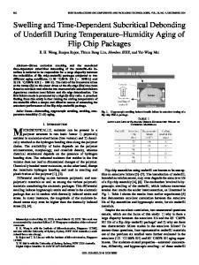
Fig. 3. Four-bus example system.
Equations (13) and (14) can be combined as Equation (20) can then be transformed into (15) is obtained by replacing the last row of with , while and are the same as and , except that elements in their last row are set to 0 so that (14) is satisfied. is not singular, the nonzero-sequence compoNow that nents of the voltages on the primary side can be determined by where
(22)
(16) Similar results can be obtained for forward sweep calculation (17) is the nonzero-sequence component of where is the same as , except that the last row is replaced with , and are obtained by setting the elements in to 0, respectively. the last row of and or are calOnce the nonzero-sequence components of culated, zero-sequence components are added to them to form the line-to-neutral voltages so that the forward/backward sweep procedure can continue. As an example, consider the backward sweep for an untransformer. According to Table I grounded
(18) and
(19)
E. Modified Forward/Backward Sweep Algorithm With the above transformation, the equations for transformer voltage calculation are no longer singular. However, the resulted and only contain the positive and transformer voltages negative sequence components. Thus, zero-sequence voltages must be added to them to form line-to-neutral voltages. The primary-side zero-sequence voltage can be initialized to 0 and is updated during the forward sweep. Since voltages are also calculated when line currents are updated, the secondary-side zero-sequence voltage can be obtained directly from the backward sweep. To illustrate the modified procedure, a four-bus example shown in Fig. 3 is used. 1) Initialization: The forward/backward sweep algorithm begins with all the load information and only the source voltage known. A guess value is given to the voltages on bus 4. given, the load currents can 2) Backward Sweep: With be calculated. If the transformer core loss is modeled on the secondary side, core loss functions can be used to determine the absorbed power and current. Thus, the three-phase currents that flows through feeder 3–4 can be obtained. Assume that line charging is neglected, then the currents flowing through the secare equal to . The voltages ondary side of the transformer on the secondary side of the transformer are
Thus, (13) becomes
(20) is evident. However, the matrix The singularity of matrix can be changed to nonsingular if one of its rows is replaced with , i.e.,
(21)
where is the line impedance matrix for feeder segment 3–4. -connected transformer, its matrix is not For the invertible. According to (16)
Since only contains the positive-and negative-sequence , an initial value of zero-sequence voltage components of is needed to get the transformer primary side voltage
XIAO et al.: UNIFIED THREE-PHASE TRANSFORMER MODEL FOR DISTRIBUTION LOAD FLOW
Next the currents at the ungrounded Wye side can be determined with
157
V
TABLE III DURING ITERATIONS
The backward sweep calculation continues until the source bus is reached. If the difference between the computed source and the actual source voltage is not within the voltage required error limit, a forward sweep is performed. 3) Forward Sweep: The forward sweep begins by setting to its actual value . Since the currents in feeder sections 1–2 have been calculated in the backward sweep, the voltage at bus 2 can be obtained by
where is the line impedance matrix for feeder segment , the zero-sequence component 1–2. Note that by updating is also updated and will be used in the next backward sweep procedure. based on the knowledge The next step is to determine and . Still, due to matrix singularity, only positive-and of negative-sequence components can be determined
The voltage can then be calculated by adding zero-sequence voltage , which is obtained from the last value of in backward sweep. The forward sweep then continues until bus 4 is reached. 4) Zero-Sequence Voltage Update: As illustrated above, for or submatrices, zero-setransformers with singular quence voltage update calculation cannot be performed from one side to the other. This is due to the fact that zero-sequence equivalent circuit is interrupted at a transformer with windings. Hence, the zero-sequence ungrounded Y and/or voltage on one side of the transformer cannot be determined based on line-to-neutral voltages on the other side, even when line current information on both sides is available. In these cases, the zero-sequence voltages on the primary side can be updated by the source voltage during the next forward sweep. However, the zero-sequence voltages on the secondary side with a or ungrounded Y winding will not be updated due to the lack of voltage reference point on the secondary side, which makes determining the real line-to-neutral voltage impossible. To avoid such difficulties, the method in [9] used the lineor ungrounded Y side of the transto-line voltage on the former and the line-to-neutral voltage in the remaining part of the system. The method in [5] introduced an arbitrary reference neutral point to convert the line-to-line voltages to the line-to-neutral voltages. The proposed method, using an initially guessed zero-sequence voltage on the primary side, does not reor ungrounded quire any special treatment in handling the Y transformers. With this initial zero-sequence voltage, line-toneutral voltages can be used throughout the system. The primary-side zero-sequence voltages are updated by the source voltage. The zero-sequence voltage on the secondary or ungrounded Y winding are determined by side with a
grounded elements that are connected to the same side of the transformer, such as grounded load, line charging, or other grounded transformers. However, due to the limitations of forward/backward sweep algorithm [11], zero-sequence voltage cannot be updated. Therefore, the secondary line-to-neutral voltages in these conditions are the assumed value. The common practice in the utility industry will seldom see a single phase-to-ground load connected to an ungrounded three-phase source or transformer, so the zero-sequence current is generally very small compared with load currents. Thus, even if the calculated line-to-neutral voltage is not real, the corresponding line-to-line voltage is still accurate. IV. TEST EXAMPLES To verify the proposed method, different transformer configurations were included in a three-phase distribution load flow program with a forward/backward sweep algorithm. Two different sized examples were implemented, and results were compared with other existing methods. A. Model Validation The IEEE four-node test feeder [12] was used to provide a simple system for the testing of various three-phase transformer connections. The one-line diagram of the example is shown in Fig. 3. The two distribution feeder segments have unequal mutual coupling between the phases. The load is unbalanced with different kilovoltampere and power factor in each phase. transformer connection, the proFor an ungrounded gram terminates after five iterations, and the difference between and specified source voltage computed source voltage are within 0.0001 p.u. The -phase line-to-line voltages at the load are listed in Table III. The results match very well with those listed in [9], where a detailed step-by-step example was given. Tests have been conducted for all other transformer connections, and the results match those listed in [12]. However, the method mentioned in [9] and [12] requires different sets of equations for different transformer configurations, which is not convenient for efficient implementation and incorporation of new connection types. The unified method proposed in this paper does not require any special equations to handle the transformers with the or ungrounded Y windings.
158
IEEE TRANSACTIONS ON POWER SYSTEMS, VOL. 21, NO. 1, FEBRUARY 2006
TABLE IV ZERO-SEQUENCE VOLTAGES AT BUS 2
TABLE VI LINE-TO-LINE VOLTAGES AT BUS 4
TABLE V ZERO-SEQUENCE VOLTAGES AT BUS 4
B. Zero-Sequence Voltage Update Different transformer configurations were implemented in the four-bus example to further test the updating behavior of the zero-sequence voltage. Two different initial values (0 and 0.1 p.u.) were chosen for each configuration. If different initial values always converge to the same final value, then it means the zero-sequence voltage can be correctly updated during the iterations for the given type of transformer configuration. Table IV shows the final zero-sequence voltages on the primary side of the transformer for different connection types. The results show that, for each transformer configuration, the primary side zero-sequence voltage always converges to a similar value, regardless of its initial value. These results indicate that the primary side zero-sequence voltage can be updated. This update takes place during the forward sweep, and it is due to the Y-grounded source voltage. Table V shows the final zero-sequence voltages on the secondary side (bus 4) of the transformer. The results indicate that for some transformer configurations, different initial values will produce different final values. This is true for every transformer and . The results further configuration except show that forward/backward sweep algorithm cannot produce unique secondary line-to-neutral voltages in these cases. It is should be noted that the initial zero-sequence voltage . obtained from the initial leaf-node voltages For and transformers, zero-sequence voltage on one side can be uniquely determined from voltages on the
Fig. 4.
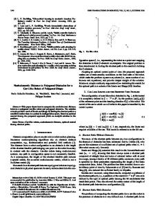
IEEE 123-bus example system.
other side together with current information. For other connections, a close examination reveals that the final values are in the vicinity of the initial value. In other words, zero-sequence voltages are not updated, even though the algorithm converges. This is due to the fact that without additional grounding devices on the secondary side, the subnetwork is isolated, and the zero-sequence voltage will not be affected by other part of the system. Table VI shows the corresponding line-to-line voltages at bus 4 for different transformer configurations with different initial zero-sequence voltages. The results indicate that even though different initial values may produce different final zero-sequence voltages, the corresponding line-to-line voltages are correct when the algorithm converges, which meets the requirement for most load flow analysis. C. Large System Tests The IEEE 123-bus example shown in Fig. 4 is used to demonstrate the transformer models in large systems. The load flow analysis calculation was performed using per-unit values on a basis of 115 kV/4.16 kV/480 V and 10 MVA. There are two transformers in this system. One is located between nodes 150 and 149, and the other is between nodes 61 and 610. Extensive tests have been performed on the system to verify the validity of the proposed method. Comparisons have been made against transformer modeling approaches developed in [4]
XIAO et al.: UNIFIED THREE-PHASE TRANSFORMER MODEL FOR DISTRIBUTION LOAD FLOW
TABLE VII ITERATION NUMBERS FOR DIFFERENT SYSTEM LOADING CONDITIONS
159
the corresponding zero-sequence voltage cannot be updated. This paper also proves that the line-to-neutral voltage, excluding its zero-sequence component, can still be used in the forward/backward sweep. Based on these findings, the proposed technique separates the zero and nonzero sequence voltage during the forward/backward sweep, regardless of the transformer configuration to avoid the singularity problem. For certain transformer connections, the zero-sequence voltage on the secondary side cannot be updated during the sweeps. The proposed method was implemented in two different sized examples, and tests were conducted to compare with other existing approaches. The results show the validity and effectiveness of the proposed technique. REFERENCES
TABLE VIII ITERATION NUMBERS FOR DIFFERENT R/X RATIOS
and [5]. For convenience, the proposed modeling method is labeled model 1 in the tables, and methods in [5] and [4] are labeled model 2 and model 3, respectively. Table VII compares the results under different loading conditions, and Table VIII compares the results under different R/X ratios. It appears that there is a strong agreement in terms of the resultant bus voltages and branch currents among the three models under all test conditions. From the results, it is observed that as the load increases, the number of iterations for convergence increases irrespective of the models. However, model 1 and model 2 appear to be less sensitive than model 3. Results further reveal that the iteration numbers for model 3 are larger than that of model 1 and 2. The major reason is that in model 3, the injection currents of all the equivalent current sources are calculated based on voltages obtained in the previous iteration, instead of the updated voltages. Even though the computation time needed for each iteration is less for model 3, the smaller amount of voltage/current update makes the total iteration number much higher. It can be seen that with increases in R/X ratios, all the models exhibit poor convergence, although model 1 and model 2 are less sensitive. V. CONCLUSION A unified method to incorporate three-phase transformers into the forward/backward sweep-based distribution load flow is presented. The singularity issues existing in certain transformer configurations were thoroughly examined. This paper indicates that the singularity appears only in certain transformer submatrices and only in certain transformer connections. This paper shows that when the singularity occurs,
[1] W. H. Kersting, Distribution System Modeling and Analysis. Boca Raton, FL: CRC, 2002. [2] G. J. Chen, K. K. Li, T. S. Chung, and G. Q. Tang, “An efficient two-stage load flow method for meshed distribution networks,” in Proc. APSCOM, 2000, pp. 537–542. [3] M. H. Haque, “Efficient load flow method for distribution systems with radial or mesh configuration,” Proc. Inst. Elect. Eng., Gener., Transm., Distrib., vol. 143, no. 1, pp. 33–38, Jan. 1996. [4] T. H. Chen, M. S. Chen, T. Inoue, P. Kotas, and E. A. Chebli, “Threephase cogenerator and transformer models for distribution system analysis,” IEEE Trans. Power Del., vol. 6, no. 4, pp. 1671–1681, Oct. 1991. [5] M. E. Baran and E. A. Staton, “Distribution transformer models for branch current based feeder analysis,” IEEE Trans. Power Syst., vol. 12, no. 2, pp. 698–703, May 1997. [6] R. C. Dugan, “A perspective on transformer modeling for distribution system analysis,” in Proc. IEEE Power Eng. Soc. General Meeting, vol. 1, Jul. 2003, pp. 114–119. [7] M. J. Gorman and J. J. Grainger, “Transformer modeling for distribution system studies part I: Linear modeling basics,” IEEE Trans. Power Del., vol. 7, no. 2, pp. 567–574, Apr. 1992. , “Transformer modeling for distribution system studies part II: Ad[8] and Z ,” IEEE Trans. Power Del., vol. 7, dition of models to Y no. 2, pp. 575–580, Apr. 1992. [9] W. H. Kersting and W. H. Phillips, “A new approach to modeling threephase transformer connections,” IEEE Trans. Ind. Appl., vol. 35, no. 1, pp. 169–174, Jan. 1999. [10] M. R. Irving and A. K. Al-Othman, “Admittance matrix models of three-phase transformers with various neutral grounding configurations,” IEEE Trans. Power Syst., vol. 18, no. 3, pp. 1210–1212, Aug. 2003. [11] Z. Wang, F. Chen, and J. Li, “Implementing transformer nodal admittance matrices into backward/forward sweep-based power flow analysis for unbalanced radial distribution systems,” IEEE Trans. Power Syst., vol. 19, no. 4, pp. 1831–1836, Nov. 2004. [12] W. H. Kersting, “Radial distribution test feeders,” in Proc. IEEE Power Eng. Soc. Winter Meeting, vol. 2, Jan. 2001, pp. 908–912. [13] A. Tan, W. H. Liu, and D. Shirmohammadi, “Transformer and load modeling in short circuit analysis for distribution systems,” IEEE Trans. Power Syst., vol. 12, no. 3, pp. 1315–1332, Aug. 1997.
Peng Xiao (S’04) received the M.S. degree in electrical engineering from North China Electric Power University, Beijing, China, in 2000. He is currently working toward the Ph.D. degree at the University of Wisconsin-Milwaukee.
David C. Yu (M’84) is currently a Full Professor with the Department of Electrical Engineering and Computer Science, University of Wisconsin-Milwaukee.
Wei Yan received the Ph.D. degree in electrical engineering from Chongqing University, Chongqing, China, in 1999. Currently, he is an Associate Professor and Associate Chairman of the Electrical Power Department, Electrical Engineering College, Chongqing University. His research interests include optimal operation and control in power systems.