Pulse source based on directly modulated laser and phase modulator Hao Hu1, Jinlong Yu1*, Litai Zhang1, Aixu Zhang1, Yan Li2, Yang Jiang1, and Enze Yang1 1
2
School of Electronic Information Engineering, Tianjin University, and Key Laboratory of Opto-electronic Information Science and Technology, Ministry of Education, Tianjin 300072, China, School of Precision Instrument & Opto-electronics Engineering, Tianjin University, Tianjin 300072, China, Email:
[email protected]
Abstract: We propose the simple pulse source, in which the pulses generated by large-signal directly modulated laser diode are phasemodulated, and then compressed into short pulses by an optimized length of DCF. On the one hand, phase modulator is used to enhance the negative chirp of large-signal directly modulated pulses. On the other hand, the largesignal directly modulated pulses are used to suppress the pedestal produced by the phase modulator. Using this technique, highly stable 10-GHz 5.5-ps optical pulses are obtained, which suppress pedestal up to 20dB and have a low timing jitter of 184fs. ©2007 Optical Society of America OCIS codes: (060.2330) Fiber optics and optical communications: Optic communication; (060.5060) Fiber optics and optical communications: Phase modulation; (320.5550) Ultrafast optics: Pulses; (320.1590) Ultrafast optics: Chirping.
References and links 1. B. Bakhshi and P. A. Andrekson, “40 GHz actively modelocked, polarization maintaining erbium fiber ring laser,” Electron. Lett. 36, 411–413 (2000). 2. P. Gunning, J. K. Lucek, D. G. Moodie, K. Smith, R. P. Davey, S. V. Chernikov, M. J. Guy, J. R. Taylor and A. S. Siddiqui, "Gainswitched DFB laser diode pulse source using continuous wave light injection for jitter suppression and an electroabsorption modulator for pedestal suppression," Electron. Lett. 32, 1010-1011 (1996). 3. V. Torres-Company, J. Lancis, and P. Andrés, “Unified approach to describe optical pulse generation by propagation of periodically phase-modulated CW laser light,” Opt. Express 14, 3171 (2006). 4. C. Yu, L.-S. Yan, T. Luo, Y. Wang, Z. Pan, and A. E. Willner, “Width-tunable optical RZ pulse train generation based on four-wave mixing in highly nonlinear fiber,” IEEE Photon. Technol. Lett. 17, 636-638 (2005). 5. S. Iezekiel, C. M. Snowden, and M. J. Howes, “Generation of ultrashort optical pulses by microwave modulation of laser diodes,” IEE Colloquium on Applications of Ultrashort Pulses for Optoelectronics, 9/1 9/7 (1989). 6. T. E. Murphy, “10-GHz 1.3-ps pulse generation using chirped soliton compression in a Raman gain medium,” IEEE Photon. Technol. Lett. 14, 1424-1426 (2002). 7. G. J. Spiihler, M. Dymott, I. Klimov, G. Luntz, L. Baraldi, I. Kilburn, P. Crosby, S. Thomas, 0. Zehnder, C. Y. Teisset, M. Brownell, K. J. Weingarten, R. Dangel, B. J. Ofiein, G. L. Bona, 0. Buccafusca, Y. Kaneko, L. Krainer, R. Paschotta, and U. Keller, “40 GHz pulse generating source with less than 350 fs timing jitter,” Electron. Lett. 38, 1031-1033 (2002) 8. T. Komukai, T. Yamamoto, and S. Kawanishi, “Optical pulse generator using phase modulator and linearly chirped Fiber Bragg Gratings,” IEEE Photon. Technol. Lett. 17, 1746-1748 (2005). 9. T. Otsuji, M. Yaita, T. Nagatsuma, and E. Sano, “10–80-Gb/s highly extinctive electrooptic pulse pattern generation,” IEEE J. Sel. Tops. Quantum Electron. 2, 643–649 (1996). 10. M. Osinski and J. Buus, “Linewidth broadening factor in semiconductor,” IEEE J. Quantum Electron. 23, 929 (1987) 11. C. Harder, K. Vahala, and A. Yariv, “Measurement of the linewidth enhancement factor of semiconductor lasers,” Appl. Phys. Lett. 42, 328-330 (1983). 12. K. Taira and K. Kikuchi, “Subpicosecond pulse generation using an electroabsorption modulator and a double-stage pulse compressor,” IEEE Photon. Technol. Lett. 15, 1288-1290 (2003)
#81702 - $15.00 USD
(C) 2007 OSA
Received 2 Apr 2007; revised 30 Apr 2007; accepted 3 May 2007; published 3 Jul 2007
9 July 2007 / Vol. 15, No. 14 / OPTICS EXPRESS 8931
1. Introduction High-quality and reliable short pulses have many applications in OTDM system. Several techniques have been developed to produce short pulses [1-7]. Mode-locked laser is capable of generating very short pulses with a high repetition frequency, but it requires a complex equipment to realize stable operation. Gain-switching laser is a simple and reliable short pulse source, but the generated pulse has considerable timing jitter. The pulses generated by directly modulated laser have low timing jitter, but the pulse width is usually not short enough for OTDM system. Recently, a simple optical pulse generator is reported [3] [8], in which continuous wave (CW) light is modulated by an electrooptic phase modulator and compressed into pulses by a group delay dispersive medium. However, the phase modulated CW light has both positive and negative chirp, so the compression typically results in pedestals after it passes through a group velocity dispersive medium, which makes it unsuitable for use in practical systems. Several techniques have been proposed to suppress pedestal, such as using intensity modulation and an optical bandpass filter [9]. In this paper, we report a simple and reliable optical short pulses source, in which largesignal directly modulated pulses are phase-modulated, and compressed into short pulses by an optimized length of dispersion compensation fiber (DCF). The pedestal produced by an electrooptic phase modulator can be suppressed by the large-signal directly modulated pulses. Using this technique, we obtain high-quality 5.5-ps pulses at a repetition rate of 10 GHz, with a high-pedestal suppression of up to 20dB, and 184-fs timing jitter determined by integrated phase noise over a frequency span of 100 Hz to 1 MHz. 2. Theoretical analysis It is well established that modulation of the current supply to a semiconductor laser leads to modulation of both the optical intensity and the optical frequency [10] [11]. Assuming that the pulse produced by the large-signal directly modulated laser diode is a Gaussian pulse, and the phase of the pulse changes with sinusoidal signal, the electrical field can be expressed as t2 (1) E(t ) = E0 Exp[− 2 ]Exp[− j(ω0 t + Δθ1 sin(2πf mt + π / 2))] 2T0 where E0 is the amplitude of electrical field, ω0 is the angular frequency, fm is modulation frequency, Δθ1 is the equivalent phase modulation index of large-signal directly modulated laser and T0 is the pulsewidth which is defined as half width of optical pulse when amplitude decreases to 1/e of the peak. Initial phase π/2 indicate that the pulse has negative chirp. The phase modulation index Δθ1 is directly related to the linewidth enhancement factor α of the semiconductor laser [10] [11], m (2) Δθ1 = iα 2 where m is intensity modulation index, and α can be calculated by [10], 2 P Δν (3) α = 0i 1 ΔP f m where P0 is the DC optical power, and ΔP is the peak-to-peak power excursion, Δν 1 is the optical frequency excursion, and fm is modulation frequency. If the large-signal directly modulated pulses are then phase modulated by the same frequency fm, the modulated electrical field can be expressed as E(t) = E0Exp(−
+
t2 )Exp[− j(ω0t + Δθ1 sin(2πfmt + π / 2) + Δθ2 sin(2πfmt Δϕ))] 2 2T0
(4)
where, Δθ2 is the modulation index of phase modulator, and Δϕ is the phase difference. In this case, the instantaneous frequency of the light is given by
#81702 - $15.00 USD
(C) 2007 OSA
Received 2 Apr 2007; revised 30 Apr 2007; accepted 3 May 2007; published 3 Jul 2007
9 July 2007 / Vol. 15, No. 14 / OPTICS EXPRESS 8932
+
1 ∂φ (5) = ω0 / 2π − f m Δθ1sin(2πf mt) + f m Δθ 2cos(2πf mt Δϕ) 2π ∂t Optical frequency chirp can be described as ∂ν 2 (6) = −2πf m [ Δθ 1 cos ( 2πf m t ) + Δθ 2 sin( 2πf m t + Δ ϕ )] ∂t when Δϕ=π/2, the chirp generated by the large-signal directly modulated laser has the same sign with the chirp generated by the phase modulator, and the optical frequency chirp (6) can be written as: ∂ν 2 (7) = − 2πf m ( Δθ 1 + Δ θ 2 )cos ( 2πf m t ) ∂t when t ε ((n-1/2) T, (n+1/2) T) (n is an integer), the optical frequency chirp is negative, and when t→n*T, the optical frequency chirp is almost linear, and the absolute value of the chirp reaches maximum.
ν (t) = −
ν − 2πf m Δθ 2
ω 0 / 2π
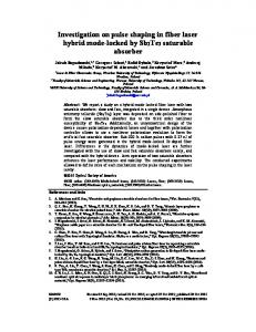
Fig. 1. Conceptual diagram (a) Large-signal directly modulated pulses with negative chirp (b) Instantaneous optical frequency of phase-modulated light
A conceptual diagram is shown in Fig. 1. By appropriately adjusting delay to make Δϕ=π/2, the negative chirp of large-signal directly modulated pulses can be enhanced, and the positive chirp of phase modulator can be prevented. The total optical frequency chirp is almost linear, with maximum negative chirp of: ∂ν 2 (8) = −2πf m ( Δθ 1 + Δθ 2 ) ∂t
Accordingly, an optimum length of DCF is used to compensate linear chirp, and the estimate optimum length of DCF can be given as: CT0 (9) L≈ D λ 2 Δν where C is optical speed in vacuum, T0 is the FWHM of large-signal directly modulated pulse, D is dispersion parameter, λ is the central wavelength of optical pulse, and Δν is the FWHM of optical spectrum. Substitute Δϕ=π/2 into (4), and after Fourier Transform, we can get the spectral function:
E(ω) = E0T0
∑J (Δθ + Δθ )i Exp[− T (ω −ω2+ 2nπf ) ] +∞
n
n=−∞
n
1
2
2 0
2
0
m
(10)
From (10), the FWHM of optical spectrum with different phase modulation index and modulation frequency can be calculated assuming that the large-signal directly modulated pulse has a duty ratio of 25%, as shown in Fig. 2. So the FWHM of optical spectrum can be approximately shown as: (11) Δν ≈ 2( Δθ 1 + Δθ 2 ) f m #81702 - $15.00 USD
(C) 2007 OSA
Received 2 Apr 2007; revised 30 Apr 2007; accepted 3 May 2007; published 3 Jul 2007
9 July 2007 / Vol. 15, No. 14 / OPTICS EXPRESS 8933
It can be seen from equation (11) and Fig. 2 that both large phase modulation index and high modulation frequency are useful to increase the spectral width.
Fig. 2. Calculated dependence of FWHM of optical spectrum on phase modulation index at different modulation frequency 5GHz, 10GHz, and 20GHz.
3. Experimental setup
Fig. 3. Experimental setup for short pulses source
Our short pulse source has a simple configuration, as shown in Fig. 3. 10GHz sinusoidal radio-frequency (RF) signals directly modulate a MQW-DFB laser (Irf=63mA, Ibias=50mA, Ithreshold=18mA), and produce 28-ps optical pulses at the wavelength of 1553 nm, as shown in Fig. 4. The optical spectrum is 0.494nm (about 62GHz in frequency), and the intensity modulation index is near 100%. The linewidth enhancement factor α can be calculated to about 6.2, so the phase modulation index Δθ1 is calculated to approximately 1.0π.
(a)
(b)
Fig. 4. Waveform (a) and optical spectrum (b) of large-signal directly modulated pulses
The large-signal directly modulated optical pulses pass through a variable optical delay line (ODL), and then are modulated by an integrated LiNbO3 phase modulator. The phase modulator is driven by the sinusoidal RF signals that are amplified by a RF amplifier. The RF power fed into the phase modulator is 23dBm, and the phase modulator index Δθ2 is approximately 0.9π. An adjustable optical delay line is used to allow temporal adjustment of #81702 - $15.00 USD
(C) 2007 OSA
Received 2 Apr 2007; revised 30 Apr 2007; accepted 3 May 2007; published 3 Jul 2007
9 July 2007 / Vol. 15, No. 14 / OPTICS EXPRESS 8934
the switching window created by the large-signal directly modulated pulses, which ensure the negative chirp of phase modulator to pass through and prevent the positive chirp. A polarization controller (PC) is used to align the polarization state of input light with the axis of phase modulator. The pulses with negative chirp that emerged from the phase modulator are then compressed into short pulses using a 147-m-long DCF (D=-142ps/nm/km) for chirp compensation. 4. Results The optical spectrum, eye diagram of sampling oscilloscope and autocorrelation trace are shown in Figs. 5(a) 5(b) and 5(c). The full-width at half-maximum (FWHM) of the optical spectrum of output short pulses is 0.912nm. The autocorrelation trace in the Fig. 5(c), measured by an intensity autocorrelation measurement with an assumption of gauss shape, shows a high quality 5.5-ps pulse with a pedestal suppression of about 20dB (limited by the measurement system resolution), which is suitable for OTDM system applications [12]. The pulse has a time-bandwidth product of 0.63, and the pulse width is limited because DCF can only compensate for linear chirp and nonlinear chirp remains. The short pulses obtained in the present scheme are limited by the modulation index of the phase modulator. One way to obtain shorter pulse is to increase the modulation voltage, and another way is to serialize several phase modulators.
(a)
(b)
(c) Fig. 5. Experimental results of short pulses source. (a) Optical spectrum. (b) Eye diagram of optical sampling oscilloscope. (c) Autocorrelation trace. The inset of graph (c) shows the autocorrelation trace in log scale.
#81702 - $15.00 USD
(C) 2007 OSA
Received 2 Apr 2007; revised 30 Apr 2007; accepted 3 May 2007; published 3 Jul 2007
9 July 2007 / Vol. 15, No. 14 / OPTICS EXPRESS 8935
(a)
(b)
Fig. 6. Characters of output without large-signal directly modulated pulses. (a) Optical spectrum. (b) Waveform.
In contrast, we remove the directly modulated microwave signal, and use it as a CW light source. Besides, we use a 306-m-long DCF (D=-142ps/nm/km) to compensating for negative chirp. The optical spectrum and waveform are shown in Figs. 6(a) and 6(b). The FWHM of optical spectrum is only 0.454nm, because it doesn’t include the phase modulation produced by large-signal directly modulation. From Fig. 6(b), we can see that the pulses have a large pedestal, whose suppression ratio is only 5.6dB, because both negative chirp and positive chirp pass through a positive dispersion medium. The negative part of chirp can be compressed into the pulse and the positive part of chirp becomes scattered light. Eye diagram accumulation of five minutes in Fig. 5(b) demonstrates the short pulses with long-term stability. Figure 7 shows the phase noise measurements with a microwave spectrum analyzer ranging from 100 Hz to 1 MHz offset frequencies. The phase noise corresponds to the RMS timing jitter of 165fs for HP 83711B signal generator, 184fs for the large-signal directly modulated pulses, 184fs for the 10 GHz short pulse source and 280fs for the phased modulated pulses without direct modulation. From Fig. 7, we can see that the phase noise of the 10 GHz short pulses source is the same as the phase noise of the large-signal directly modulated pulses, and close to the phase noise of HP signal generator. The phase noise of the phase modulated pulses without directly modulation is obviously increased relative to the 10 GHz short pulses source in the 100 KHz-1MHz regime, because the pulse produced by negative chirp can interfere with the scattered light produced by positive chirp, and beat noise is produced.
(a)
(b)
Fig. 7. Single-sideband phase noise power spectral density at 10 GHz. (a) shows 165-fs and 184-fs rms integrated timing jitter for HP 83711B signal generator and large-signal directly modulated pulses; (b) shows 184-fs and 280-fs rms integrated timing jitter for the phased modulated pulses with and without large-signal direct modulated pulses separately.
5. Conclusion In summary, the 10GHz short pulse source with a directly modulated MQW-DFB laser and a phase modulator is very simple and reliable. The method has successfully provided high
#81702 - $15.00 USD
(C) 2007 OSA
Received 2 Apr 2007; revised 30 Apr 2007; accepted 3 May 2007; published 3 Jul 2007
9 July 2007 / Vol. 15, No. 14 / OPTICS EXPRESS 8936
quality and stable 5.5ps pulses at 10GHz with low jitter of 184fs and high pedestal suppression of 20dB. This short pulse source is suitable for OTDM system, because of narrow pulsewidth, high pedestal suppression, low timing jitter, and long-term stability. Acknowledgment This work was partially supported by National Nature Science Foundation of China under Grant 60572013, Tianjin Nature Science Foundation under Grant 06YFJMJC01400, and the Program for New Century Excellent Talents in Ministry of Education of China.
#81702 - $15.00 USD
(C) 2007 OSA
Received 2 Apr 2007; revised 30 Apr 2007; accepted 3 May 2007; published 3 Jul 2007
9 July 2007 / Vol. 15, No. 14 / OPTICS EXPRESS 8937