SS 120002240—16/11/2001—SALLEN—38377
SEPARATION SCIENCE AND TECHNOLOGY, 37(5), 1–23 (2002)
PURIFICATION OF LANDFILL LEACHATE WITH MEMBRANE PROCESSES: PRELIMINARY STUDIES FOR AN INDUSTRIAL PLANT K. Tabet,1 Ph. Moulin,1,* J.D. Vilomet,2 A. Amberto,3 and F. Charbit1 1
Laboratoire d’Etudes et d’Applications des Proce´de´s Se´paratifs (LEAPS-EA 884), ENSSPICAM, Universite´ de St Je´roˆme, Avenue Escadrille Normandie Niemen, 13397 Marseille Cedex 20, France 2 CEREGE, Europoˆle Me´diterrane´en de l’Arbois, BP 80, 13545 Aix en Provence, France 3 DED, Ville de Marseille, 27 Bd Joseph Vernet, 13008 Marseille, France
ABSTRACT Purification of landfill leachates is a difficult question for which there is no general answer due to their diversity and possible evolution with time. The aim of this work was to characterize the landfill leachate considered and then to propose an efficient treatment for this effluent. The leachate analysis led us to consider a membrane separation process, namely ultrafiltration. The separation power was studied under several conditions. The results obtained show that purification is successful and we report the differences encountered using different membranes and *Corresponding author. Fax: (334) 910-27776; E-mail:
[email protected] 1 Copyright q 2002 by Marcel Dekker, Inc.
www.dekker.com
SS 120002240—16/11/2001—SALLEN—38377
2
TABET ET AL.
modules. The best results at lab-scale were performed again using bench-scale modules and finally this study makes it possible to define an efficient process for which the type of membrane, its cutoff, the experimental, and backwash conditions are determined. Good experimental conditions are quite flexible. The design of an industrial plant can be deduced, which no doubt ensures a good purification (i.e., a high chemical oxygen demand retention). Key Words: Ultrafiltration; Landfill leachate; Membrane; Industrial plant
BACKGROUND Since the beginning of the 20th century, Marseille refuses have been deposited in Crau at the Centre de Traitements Biologiques des Re´sidus Urbains (CTBRU) located in Saint Martin de Crau. Year after year, demographic growing, together with technical development and local geographic evolution, has turned this landfill into one of the major outdoor disposal sites in Europe. Rainwater passing through the landfill thickness extracts and carries contaminants; thus, it turns into wastewater, called leachate. The leachate is then gradually degraded by the bio-organisms that it contains; they naturally achieve an efficient biological treatment and wastewater coming out from the landfill is seemingly stabilized at a very high chemical oxygen demand (COD) value. In addition, standards for domestic water are increasingly strict, which reflects an increase of people’s concern. Ultimate effluent issued cannot be rejected directly. The first part of this paper concerned the leachate analysis. The results led us to consider membrane processes as a good treatment, first at lab-scale and then at bench-scale. In the second part, this paper presents how the leachate COD can be reduced substantially and determines the design of the pilot plant that is planned.
ANALYSIS OF LANDFILL LEACHATE Site Description The still-active site covers about 60 ha and its average height is 25 m. This landfill has no bottom liner, and wastes are placed directly on the ground. It is isolated from local industrial influences. The part concerned by the landfill, named Crau du Luquier, is constituted by a mix of calcareous, metamorphic, and endogenous quaternary crushed stones. The clayey sand matrix is abundant with illite, chlorite, vermiculite, and mixed layer clay (1). Subsurface investigations
SS 120002240—16/11/2001—SALLEN—38377
PURIFICATION OF LANDFILL LEACHATE
3
Q1 Q1
revealed a lateral shift of facies to a shoal caused by a paleochannel structure. The east side of the landfill may be a low from crushed stone (8 m thickness) to sandy clay (4.5 m thickness). Landfill may be on transmissivity zone. Groundwater is supplied by irrigation (70%) and rainwater by infiltration (30%). The overall flow direction is NE – SW and the hydraulic gradient is 3‰.
Materials and Methods of Analysis The groundwater quality was mapped by one piezometer located 1 km upgradient the waste disposal and two transects downgradient of the landfill. The first transect (900 m) is perpendicular to the flow direction and allows the determination of the main source of landfill leachate. Three piezometers have been investigated at a horizontal distance of approximately 300 m. Piezometers and one water well have been sampled. Water quality (pH, dissolved oxygen, temperature, and conductivity) was determined with depth (0.5 m increments) Q2 and measured in situ using electrodes in piezometers (WTW Profiline oxy 197a) equipped with a self-stirring dissolved oxygen probe (pH 197 and LF 197). Q2 Groundwater samples have been collected with a pump (Grundfos MP1) after a 15-min flush. Samples for trace-metal analyses have been collected from piezometers with acid cleaned low-density polyethylene bottles. They are stored unacidified at 48C to prevent floc formation and contamination from the bottle wall. Trace metals are measured by inductively coupled plasma and atomic absorption spectrometer. Organic matter values are determined by a total organic carbon analyzer. Nitrate, sulfate, and chloride are measured by capillary ion analysis.
Results The background groundwater quality is determined by samples taken 1 km upgradient the waste disposal. The pH is 7.1 in the entire water column. Due to seasonal agriculture contributions, chloride (19.6 –36 mg L21), sulfate (98 – 116 mg L21), and nitrate (8.5 –25 mg L21) are found in the water column. Species 21 Q3 of iron are not present in significant concentrations. NVOC is less than 2 mg L . The first transect shows that chloride concentration, organic matter concentration, and conductivity increase from the west side to the east side of the landfill. Thus, the main source of leachate seems to originate from the eastern side of the landfill. The leachate source in the aquifer is sampled in the piezometer 3. Effect of landfill on groundwater quality is reflected by a chloride concentration of 1500 ppm approximately, the organic matter (TOC) concentration equals 1500 ppm, iron concentration matches 36.5 ppm,
Color (NF T90-034) Alkalinity (NF T90-036) Suspension matter Temperature (NF T90-100) pH at 208C (NF T90-008) Conductivity at 208C Dissolved oxygen (NF T90-106) Dissolved oxygen (NF T90-106) Ammoniac Chloride (Rodier method) Sulfates (NF T90-040) Silica (Rodier method) Nitrites Nitrates (NF T90-012) Nitrates – nitrites (NF T90-012) Orthophosphates (NF T90-023) Boron (NF T90-041) Total organic carbon (NF T90-102) Hydrocarbon IR Phenol index Sodium (NF T90-019) Potassium (NF T90-019) Total aluminum . 0.1 mg L21 (NF T90-119) Total mercury (NF T90-113) Total iron .0.5 mg L21 (NF T90-112) Total manganese (NF T90-119) Total copper (NF T90-119)
Analysis
Table 1.
0.16 0.04
,0.005
26
1100 2 ,0.025 1480 1240 2
,0.5
1600 500 ,5 ,1 ,5
7.5 13,000 0.14
6200 600
Piezometer 3
0.11 0.015
0.0005
4 0.1 0.65 15 , 0.1 , 0.025
1480 17.4 7.9 1500 2.2 22 0.2 190 290
64
Piezometer 6
mS cm21 mg L21 O2 % of saturation mg L21 mg L21 mg L21 mg L21 mg L21 mg L21 mg L21 mg L21 mg L21 mg L21 mg L21 mg L21 mg L21 mg L21 mg L21 mg L21 mg L21 mg L21 mg L21
mg L21 French degree mg L21
Units
4
0.0007
200 0.05 1.5 28 ,0.1 ,0.025
13 17.7 7.5 2500 3.8 37 0.2 190 530
72
Piezometer 2
Characteristics of Landfill Leachate
SS 120002240—16/11/2001—SALLEN—38377
TABET ET AL.
Kjedhal nitrogen , 10 mg L21 (NF T90-110) Total phosphorus (NF T90-023) Total germs 378C 24 hr (NF T90-401) Total germs 228C 72 hr (NF T90-402) Total coliforms 228C (NF T90-414) Fecal coliforms (NF T90-414) Fecal streptococcus (NF T90-416) Turbidity (NF T90-033)
Total zinc (NF T90-112) Total arsenic (NF T90-119) Total cadmium (NF T90-119) Total nickel (NF T90-119) Total lead (NF T90-119) Total chromium (NF T90-199) Total selenium (NF T90-119) Total calcium (NF T90-005) Total barium (NF T90-119) Dieldrine (NF T90-120) H.C.H alpha (NF T90-120) H.C.H beta (NF T90-120) H.C.H gamma lindane (NF T90-120) H.C.H delta (NF T90-120) Fluoranthene (NF T90-115) Benzo b Fluoranthene (NF T90-115) Benzo k Fluoranthene (NF T90-115) Benzo a pyrene (NF T90-115) Benzo ghi perylene (NF T90-115) Indeno pyrene (NF T90-115) COD ND (NF T90-101) BOD5 ND (NF T90-103) Q1
3 32
.100 7.5
.100
5.2
0.12 , 0.005 , 0.005 , 0.005 , 0.005 , 0.005 0.08 0.2 0.1 0.085 0.1 0.11 95 3
, 0.002 0.005 , 0.005
0.03 , 0.005 , 0.005
.300 .300
960 1.8
0.12 0.01 0.006 0.31 0.002 0.85 ,0.002 39
.300 .300
0.18 ,0.005 ,0.005 ,0.005 ,0.005 ,0.005 ,0.010 ,0.010 ,0.010 ,0.010 ,0.05 ,0.05 105
,0.0002 0.015 ,0.005
0.04 ,0.005 ,0.0005
for 100 mL NTU
mg L21 mg L21 by mL by mL
mg L21 mg L21 mg L21 mg L21 mg L21 mg L21 mg L21 mg L21 mg L21 mg L21 mg L21 mg L21 mg L21 mg L21 mg L21 mg L21 mg L21 mg L21 mg L21 mg L21 mg L21 mg L21
SS 120002240—16/11/2001—SALLEN—38377
PURIFICATION OF LANDFILL LEACHATE 5
SS 120002240—16/11/2001—SALLEN—38377
6
TABET ET AL.
conductivity is 8 mS cm21, and dissolved oxygen concentration is below 1%. All the results of these analyses are given in Table 1.
Conclusion of the Analysis of Landfill Leachate Table 1 allows us to compare Entressen with other landfills, considered as old, recent, and intermediate, respectively [Table 2, Refs. (2 – 4)]. The new results obtained are perfectly consistent with the age of this landfill. They also provide some information about the composition: the micro-organism concentration is low, meanwhile several salts are present and a black tiny suspension, which is similar to lignin and responsible for the high COD value. These results suggest a mechanism by which the ratio BOD5/COD† would result in a surprisingly low value: the leachate contains and carries molecules produced by the biodegradation of paper and other cellulosic materials. Therefore, it might be assumed that a strong biological activity takes place around the interface between the landfill bottom and the aquifer surface; a self-purifying system could result, the residues from which are almost impossible to degrade further. Therefore, the BOD5 values measured are somewhat low. Nevertheless, in this case all the results allow us to conclude that there is no need of process constraints other than a decrease of COD below the standards: the treatment would only have to fulfill a condition of maximum COD level. For a stabilized leachate there are different treatments based on photochemical oxidation (6), aerated lagoon during the summer and winter (7,8), biogas combustion (9), activated sludge process (10,11), membrane separation (12,13), or processes coupling bioreactor and membrane (14). In our case, the ratio BOD5/COD is low, so that no treatment using activated sludge is possible. Lagoon treatment makes it possible to decrease COD from 600 to 300 mg L21, and that is the upper level required by DRIRE‡. Such an easy treatment should be prefaced with another to decrease initial COD to 600 mg L21. Photochemical oxidation was used to increase BOD5 but cannot decrease COD and biogas combustion was impossible in our case. Given that the leachate contains soluble salts and a black solid and that: .Q3 the landfill is located in PACA, where rain fluxes vary over a wide range; . the local COD standard is to date at 300 mg L21 (from DRIRE) †
BOD5/COD ratio indicates the biodegradation easiness of the sample considered. Up to 0.1, biodegradation encounters major obstacles; given that BOD5/COD equals 0.03 in this case, it can be considered that no biodegradation will occur. ‡ Direction Re´gionale Industrie Recherche Environnement.
Heavy metals Biodegradability
Age (years) PH Chemical oxygen demand (COD) (mg L21) BOD5/COD Organic compounds
5 – 10 6.5– 7.5 4000– 10,000 0.1– 0.3 5 –30% VFA þ humic and fulvic acids
,5 6.5 .10,000
. 0.3 80% Volatile fat acids (VFA) Low – medium Important Medium
Intermediate (Type 2)
,0.1 Humic and fulvic acids, small molecules (, 500 Da) Low Low
.10 .7.5 , 4000
Old (Type 3)
Classification of Landfill Leachate vs. Age [from Refs. (2,3)]
Recent (Type 1)
Table 2.
Low Very low
0.03 Humic and fulvic acids
.10 7.5– 7.9 ,4000
This Study
SS 120002240—16/11/2001—SALLEN—38377
PURIFICATION OF LANDFILL LEACHATE 7
SS 120002240—16/11/2001—SALLEN—38377
8
TABET ET AL.
we have considered membrane processes as good candidates. As membrane process, reverse osmosis (15,18) is more frequently used than ultrafiltration or nanofiltration (19) for leachate treatment. However, due to the lagoon that now exists in the landfill, it is sufficient to decrease COD to about 600 mg L21. Hereafter, this is the upper permeate COD we can obtain. Under these conditions, nanofiltration or ultrafiltration would be sufficient and the process is cheaper than reverse osmosis. MEMBRANE SEPARATIONS A short preliminary study was first undertaken, using different membranes in order to determine a possible molecular weight cut-off (MWCO) range for the separation aimed. Membranes Different membranes were tested (Table 3). The preliminary study led us to determine the best membranes for further experiments. Then, the feasibility study demonstrated that the landfill leachate could be purified efficiently by ultrafiltration using lab-scale membranes. Finally, we developed experiments at bench-scale using different industrial modules in order to determine precisely flexible experimental conditions for the plant.
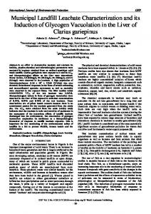
Experimental Set-Up The preliminary experiments were carried out in a ultrafiltration cell provided by Amicon (model 8200) of 200 mL capacity. This dead-end filtration Q2 cell can hold membrane discs of 4.2 cm diameter. The cell was pressurized with air. The experiments were carried out at 2.5 kPa as transmembrane pressure (TMP). Before collecting the permeate, the cell was equilibrated at least 5 min. The experimental set-up used in the feasibility study is shown in Fig. 1. The fluid, well stirred in the feed tank (10 L), is maintained at controlled temperature. A feed screw pump (PCM 2200F4, Moineau, Vanves, France) (A) ensures the circulation of the fluid and a by-pass (B) allows us to control the fluid velocity in the membrane module (C). In these experiments, permeate and retentate are totally recycled to the feed tank (D) in order to keep constant the composition of the upstream solution. At constant temperature, pressure, and cross-flow, experiments were therefore carried out under steady-state conditions; this is always achieved after a few minutes as verified by collecting successive permeate samples.
Mineral, Tubular
T1-70 1P19-40GL
Kerasep
Mineral Tubular
H10 P3-20
Organic (polysulfone) Plane
Chemistry, Geometry
Organic (polysulfone) Hollow fibers
H1 P3-20
M-2 YM 10 YM 3 YM 1 YC 05
Membrane
5000
1000
3000
20,000 10,000 3000 1000 500
Cut-Off (Da)
Industrial part Feasibility study Industrial part Industrial part
5.5 £ 1024 2.4 £ 1021 2.3 £ 1021
Feasibility study
6 £ 1022 9 £ 1021
Preliminary study
Part in This Study
1.38 £ 1023
Surface (m2)
Table 3. Membrane Characteristics
Rhodia-Orelis
US Filter
Millipore
Millipore
Reference
SS 120002240—16/11/2001—SALLEN—38377
PURIFICATION OF LANDFILL LEACHATE 9
SS 120002240—16/11/2001—SALLEN—38377
10
TABET ET AL.
Figure 1. Filtration set-up: (A) pump, (B) by-pass, (C) module, (D) tank, (E) retentate valve, (F, F0 ) pressure indicators, and (G) flowmeter. Q2 Q2 Q2 Q2
The pressure is controlled by gradually closing the valve (E), and TMP is defined as the mean value of upstream (F) and downstream (F0 ) pressures (MGS10/3-63, Serv’instrumentation, Irigny, France). The difference between these values is called pressure drop (DP ). The circulation flow rate is calculated using a flowmeter (G) (1307, Brooks Instrument, Veenendaal, Holland) and permeate mass measurements using a balance (SPO 61, Scaltec, Heiligenstadt, Germany). During filtration, temperatures of permeate and retentate are controlled. Separation experiments were carried out at different cross-flow velocities. At each velocity, the permeate flux was measured at different TMPs. The TMP was increased gradually until a limiting flux was reached. The values of the permeate fluxes were reconsidered at 208C, due to variations in viscosity linked to temperature. After each experiment, the membrane was cleaned carefully until initial permeability coefficient was reached for pure water.
RESULTS AND DISCUSSION Preliminary Study: Membrane Cut-Off The results obtained using Amicon Cell are given in Table 4. M-2 and YM10 membranes yield COD permeates, which exceed those requested for the industrial plant (600 mg L21) contrary to YC 05 membrane, which decreases
SS 120002240—16/11/2001—SALLEN—38377
PURIFICATION OF LANDFILL LEACHATE Table 4.
11
Chemical Oxygen Demand (COD) Variations for Different Membrane Cut-Off
Membranes Landfill leachate M-2 YM 10 YM 3 YM 1 YC 05
Cut-Off (Da)
COD (mg L21)
Aspect of Permeate
20,000 10,000 3000 1000 500
1300 1100 905 700 435 ,100
Black Black Black and clear Dark yellow and clear Yellow and clear Colorless and clear
permeate COD under 100 mg L21. This excellent result was not considered for further experiments due to the permeate flux, which is very low and would finally require high membrane surfaces. Given that the COD of the leachate considered, principally comes from solutes with molecular weights less than 3000, medium cut-off were chosen for the feasibility study. This is in agreement with published results on the treatment of an other landfill leachate (18).
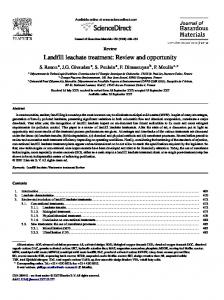
Feasibility Study Using two different lab-scale modules (H1 P3-20, T1-70) with the convenient MWCO previously determined, we investigated the purification of the landfill leachate. At constant velocity and different TMP, permeate COD was measured for samples collected from the organic membrane module. All over the TMP variation range, the permeate COD is constant around 660 mg L21. Similar results were obtained using the mineral membrane module. The COD values mentioned hereafter are those obtained with the minimum TMP. Figures 2 and 3 show the variations of permeate flux against the TMP at different cross-flow velocities for organic and mineral membrane modules. The permeate flux is expressed in L hr21 m22, which is the usual industrial unit. Before every experiment, the initial state of the membrane is verified by measuring pure water permeability coefficient Lp0 at 208C. At the end of every experiment and before membrane regeneration, pure water permeability was measured and the same value was obtained: it is the permeability after fouling. Thin lines in Figs. 2 and 3 show this fouling effect compared with pure water flux. At rather high velocities, Figs. 2 and 3 clearly show that the permeate flux is not influenced by velocity at a given TMP. In contrast, at low velocities, the increase in permeate flux seem to be less and less as soon as TMP is sufficient: a plateau value called “limiting flux” is reached. Similar results were obtained with the mineral membrane module.
SS 120002240—16/11/2001—SALLEN—38377
12
TABET ET AL.
Figure 2. Variations of permeate flux vs. TMP at different velocities (organic membrane module, COD0 ¼ 1500 mg L21 ; T ¼ 208C; d i ¼ 0:5 mmÞ:
Mineral membrane module yields permeate COD lower than the upper limit given as 600 mg L21 (Table 5). Organic membrane module gives permeate COD close to this value (700 ^ 50 mg L21). The experimental error range is ^ 50 mg L21 and the results are in agreement with those obtained in the preliminary study with respect to permeate COD vs. MWCO. Moreover, there is no influence of velocity on permeate COD either with mineral or organic membrane. It can be concluded from lab-scale results that the operating velocity in the final plant can be determined only with respect to the permeate flux (18) given that the velocity does not have a strong influence on the permeate composition. Moreover,
Figure 3. Variations of permeate flux vs. TMP at different velocities (mineral membrane module, COD0 ¼ 1300 mg L21 ; T ¼ 208C; d i ¼ 7 mmÞ:
SS 120002240—16/11/2001—SALLEN—38377
PURIFICATION OF LANDFILL LEACHATE
13
Table 5. Permeate Chemical Oxygen Demand (COD) at Different Velocities (Mineral Membrane Module: T1-70, T ¼ 208CÞ Velocity (m sec21)
Permeate COD (mg L21)
COD0 ¼ 1300 mg L21 0.9 1.4 1.8 2.3 2.8
470 335 420 310 420
the higher the TMP is, the higher the permeate flux. The industrial plant should be able to treat 2 m3 hr21, so that with medium velocity and minimum TMP as operating conditions, the membrane surface required could be estimated as: 50 m2 of organic membrane [yielding 40 L hr21 m22 (under 150 kPa)] or 33 m2 of mineral membrane [yielding 60 L hr21 m22 (under 400 kPa)]. Mineral membrane is attractive in terms of lower permeate COD, higher permeate flux, and lower membrane area. However, the equipment cost (3800 – 7600 =C m22) is not attractive compared with that of organic membrane (380 – 760 =C m22). It is now clearly demonstrated that a membrane process is efficient to purify this landfill leachate. However, some further experiments are still necessary in order to define the process the final retentate volume and membrane washing operation were studied using industrial modules.
Industrial Modules Permeate COD and permeate fluxes were measured in the same way as that described for lab-scale modules.
Organic Membrane Modules The initial feed COD is 1300 mg L21 and under these conditions the permeate COD is lower than or close to the upper limit (600 mg L21). In terms of permeate flux, the variation vs. TMP is in agreement with the results obtained with lab modules (Fig. 4). We thus performed a series of concentration experiments, including cleaning procedures.
SS 120002240—16/11/2001—SALLEN—38377
14
TABET ET AL.
Figure 4. Experimental permeate flux vs. TMP obtained with industrial and lab-scale modules (organic membrane, d i ¼ 0:5 mm; COD0 ¼ 1300 mg L21 Þ:
The initial permeability for pure water was 82 L hr21 bar21 m22. Further results are shown in Fig. 5. After the first experiment and a backwash with sodium chloride (0.2 N, TMP ¼ 200 kPaÞ; the water permeability decreased to 62 L hr21 bar21 m22 (2 25%). Analogous experiments and similar cleaning procedures were carried out. Successive permeability measurements obviously showed that the membrane was modified gradually. Therefore, the membrane Q1 washing was changed and an additional wash with ultrazyne was introduced in the procedure. As expected, the permeability coefficient was recovered close to 62 L hr21 bar21 m22. The 25% difference with the initial permeability of the new
Figure 5. Pure water permeability coefficients at the beginning of successive experiments (H10 P3-20, T ¼ 208CÞ:
SS 120002240—16/11/2001—SALLEN—38377
PURIFICATION OF LANDFILL LEACHATE
Figure 6. 208CÞ:
Q1
15
Permeate flux vs. time (H10 P3-20; v ¼ 0:52 m sec21 ; TMP ¼ 138 kPa; T ¼
membrane is encountered frequently according to the literature on this subject. However, organic membrane modules require a backwash with ultrazine for complete regeneration and constant permeability. A 29-L initial volume was filtered without permeate recycling. The final retentate volume was 0.4 L. It was observed that COD retentate increased and that the corresponding permeate flux decreased (Fig. 6). The COD permeate also increased and was finally 1500 mg L21. Though the lowest permeate fluxes could be considered as reasonable, the permeate COD was found to be higher than the upper acceptable limit. Due to the complex cleaning procedure together with the mean permeate COD, which is close to the upper limit, organic membrane modules were no longer considered as a possible treatment for the landfill leachate despite their cost advantages. Mineral Membrane Modules Different modules were tested. P19-40GL Cut-Off 1000 Da Concentration experiments were performed. First, the feed volume tank was maintained constant at its initial value (10 L) by fresh landfill leachate added to the feed at the same flux as permeate (diafiltration). In all, 50 leachate liters were treated in this way and then addition of fresh leachate was stopped.
SS 120002240—16/11/2001—SALLEN—38377
16
TABET ET AL.
Figure 7. Variations of permeate flux vs. time (1P19-40GL, TMP ¼ 500 kPa; T ¼ 208C; v ¼ 3:8 m sec21 Þ:
Filtration was carried on, until the final retentate volume was 2 L. The variations of permeate flux vs. time are presented in Fig. 7. The permeate flux first decreases during about 1 hr until it stabilizes around 30 – 35 L hr21 m22. At the same time, the feed COD continuously increases, and is finally 12,000 mg L21 at the end of the concentration procedure. The respective variations permeate COD and retentate COD vs. time are shown in Fig. 8. It can be seen that both COD values increase from the beginning, but in different ways. From 50 min on, the retentate COD increases more strongly than that of the permeate, which remains lower
Figure 8. Variations of the permeate COD and retentate COD vs. time (1P19-40GL, TMP ¼ 500 kPa; T ¼ 208C; v ¼ 3:8 m sec21 Þ:
SS 120002240—16/11/2001—SALLEN—38377
PURIFICATION OF LANDFILL LEACHATE
17
Q1
Figure 9. Variations of the permeate COD vs. retentate COD (1P19-40GL, TMP ¼ 500 kPa; T ¼ 208C; v ¼ 3:8 m sec21 Þ:
than 600 mg L21. As soon as concentration starts (no addition of fresh leachate), both COD values increase, particularly that of feed. Figure 9 shows the variations of the permeate COD vs. the retentate COD. Permeate COD remains lower than 600 mg L21 until retentate COD is lower than 4000 mg L21. Beyond this concentration, permeate COD exceeds the limit, though the membrane retention is still strong. The membrane retention (Rt) is defined by: Rt ¼ 1 2 CODpermeate =CODretentate Figure 10 presents Rt variations against time. It can be seen that the initial retention factor is around 60% and that it increases to reach a constant value around 90% from 3000 to 12,000 mg L21 as feed COD. For this mineral membrane module, there is no need of refined cleaning procedure: a usual acid – base wash is sufficient to recover totally the initial permeability coefficient after each experiment (Lp < 30 L hr21 m22 bar21). Taking into account the permeate flux, the permeate COD, and the easiness of the wash procedure, mineral membranes seem to be the best equipment for an industrial plant. However, given that the cut-off is defined specifically by each provider, we have tested a second industrial module, containing Kerasep membrane provided by Rhodia-Orelis. Q2
Kerasep Membrane: Cut-Off 5000 Da The permeate obtained from the same initial feed COD at 1400 mg L21, has a COD lower than 600 mg L21. At constant velocity, the permeate fluxes measured vs. increasing TMPs are shown in Fig. 11. The permeate flux is similar whatever the velocity, as it was observed previously. Though the cut-off given as
SS 120002240—16/11/2001—SALLEN—38377
18
TABET ET AL.
Figure 10. Variations of the retention factor vs. time (1P19-40GL, TMP ¼ 500 kPa; T ¼ 208C; v ¼ 3:8 m sec21 Þ: Q1
reference is higher than that of the US Filter equipment, the performance obtained is similar. No limiting flux was observed in our experimental ranges. Concentration experiments were carried out in the same way as previously mentioned. The variations of permeate flux and permeate COD vs. time are shown in Figs. 12 and 13, respectively. At the beginning, the permeate flux decreases and stabilizes about 15 L hr21 m22 bar21. It decreases very slowly, while the corresponding retentate COD increases. After 200 min, diafiltration stops and concentration takes place. A strong flux decrease is then observed. However, permeate COD remains about 450 mg L21 (much lower than 600 mg L21) until retentate COD is lower than 7200 mg L21 (Fig. 14).
Figure 11. Variations of the permeate flux vs. TMP at different velocities (Kerasep membrane, COD0 ¼ 1400 mg L21 ; T ¼ 208C; d i ¼ 3:5 mmÞ:
SS 120002240—16/11/2001—SALLEN—38377
PURIFICATION OF LANDFILL LEACHATE
19
Figure 12. Variations of the permeate flux vs. time ðv ¼ 1:94 m sec21 ; Ptm ¼ 4:25 bar; T ¼ 208CÞ:
Comparison of Mineral Membranes Figures 15 and 16 show permeate COD and permeate fluxes vs. COD retentate obtained using the two types of mineral membranes. Permeate COD were always found higher with the US Filter membrane. Moreover, the upper
Figure 13. Variations of the permeate COD vs. time ðv ¼ 1:94 m sec21 ; Ptm ¼ 4:25 bar; T ¼ 208CÞ:
SS 120002240—16/11/2001—SALLEN—38377
20
TABET ET AL.
Figure 14. Variations of the permeate COD vs. retentate COD ðv ¼ 1:94 m sec21 ; Ptm ¼ 4:25 bar; T ¼ 208CÞ:
feed concentration required to obtain satisfying permeate (4200 mg L21) is lower than that observed using Rhodia-Orelis membrane (9000 mg L21). In terms of permeate flux, Rhodia-Orelis membrane performance can be two times better. For these modules and this leachate, initial permeability is recovered totally in return for a simple wash.
Figure 15. Variations of the permeate COD vs. retentate COD for the two mineral membranes.
SS 120002240—16/11/2001—SALLEN—38377
PURIFICATION OF LANDFILL LEACHATE
21
Figure 16. Variations of the permeate flux vs. retentate COD for the two mineral membranes.
CONCLUSION This study describes the analysis of a landfill leachate and a filtration treatment for this effluent. Preliminary results obtained with an AMICON cell determined a range of cut-off for further investigations and feasibility study. They led us to prefer an ultrafiltration process to reverse osmosis for evident economical reasons. A feasibility study was then performed under constant concentration obtained by recycling the initial leachate. Organic and mineral membranes were compared and it was clearly established that: . qualitatively, the results are in agreement with those obtained in the preliminary study; . the permeate COD variations are similar, and the fluid velocity does not seem to have a noticeable influence; . higher permeate fluxes can be obtained using mineral membrane, which in addition can be used under higher pressures; . membrane regeneration is easier in the case of mineral membrane: a simple wash is sufficient to recover totally the initial permeability of the membrane. In contrast, organic membranes are 80% regenerated in return for an enzymatic wash. Although a disadvantage, these membranes have been investigated thoroughly due to their attractive cost. Then different membranes were tested using industrial modules at benchscale. These results perfectly ensure scaling up. The results obtained at constant concentrations are in agreement with those obtained during the feasibility study.
SS 120002240—16/11/2001—SALLEN—38377
22
TABET ET AL.
However, at increasing concentrations, organic membranes yield decreasing permeate fluxes the COD of which exceed the upper limit required. In addition, initial permeability is not totally recovered even after an enzymatic treatment. In contrast, the decrease of permeate flux at increasing feed concentration is smoother in the case of mineral membrane and the permeate COD remains lower than the standard aimed, as soon as the upstream concentration is lower than 4500 mg L21. An industrial pilot can now be designed now with this mineral and the purification process is flexible, efficient, and totally defined.
REFERENCES 1. 2. 3. Q4
4.
5. Q5
6. 7.
8.
9. 10.
11.
12.
Colomb, E.; Roux, R.M. La Crau Donne´es Nouvelles et Interpre´tations. Ge´ol. Me´d. 1978, 3, 303 –324. Chian, E.; Dewalle, F. Characterization of Soluble Organic Matter in Leachate. Environ. Sci. Technol. 1977, 11 (2), 158– 162. Millot, N. Les Lixiviats de De´charge Controˆle´e. Thesis, INSA, Lyon, France. Trebouet, D.; Le Coupannec, F.; Morin, D.; Peyrn, J.J.; Jaouen, P.; Quemeneur, F. Fractionnement et Caracte´risation des Lixiviats. Abstract of Papers. J. I. E. Poitiers 1996, 73, 1 –16. Edeline, F. L’e´puration des Lixiviats de De´charge. Trib. L’eau 1993, 566, 57 –65. Deswaef, S.; Baı¨dak, S.; Crine, M. Oxydation Photochimique de Lixiviats de De´charge. Trib. L’eau 1998, 590/591, 79 – 86. Vasel, J.L.; Vandevenne, L.; Berger, P. Epuration Par Lagunage Ae´re´ des Lixiviats D’une De´charge Controle´e de De´chets Me´nagers. Trib. L’eau 1991, 553, 7 –18. Mejbri, R.; Matejka, G.; Lafrance, P. Composition de la Matie`re Organique des Lixiviats de De´charges: Effet du Lagunage Ae´re´. Abstract of Papers. J. I. E. Poitiers 1996, 74, 1– 16. Prudhon, F. Code´pollution des Rejets des CET: Traitement des Lixiviats par Combustion de Biogaz. Environ. Technol. 1995, 143, 58– 59. Kamp, B.; Edeline, F. Ameliorations du Proce´de´ par Boues Active´es Pour e´purer un Lixiviat de De´charge D’ordure Me´nage`res. Trib. L’eau 1998, 590/591, 49– 69. Gourdon, R.; Comel, C.; Vernande, P.; Veron, J. Fractionation of the Organic Matter of a Landfill Leachate Before and After Aerobic or Anaerobic Biological Treatment. Wat. Res. 1989, 23 (2), 167 –173. Peters, T.A. Purification of Landfill Leachate with Membrane Technology. WQI Case Book 1996, 23– 26.
SS 120002240—16/11/2001—SALLEN—38377
PURIFICATION OF LANDFILL LEACHATE
13.
14.
15. 16. Q5q6
17. Q5
18.
19.
23
Trebouet, D.; Jaouen, P.; Malerlat, J.P.; Quemeneur, F. Traitement des Lixiviats de De´charge par les Proce´de´s a` Membrane. Technol. Mod. 1995, 10– 12, 26 –31. Mandra, V.; Amar, D.; Trouve, E.; Courant, P.; Coulomb, I. Couplage Biore´acteur a` Membrane et Osmose Inverse Pour le Traitement des Lixiviats de De´charge. Abstract of Papers. J. I. E. Poitiers 1994, 75, 1 –14. Linde, K.; Jo¨nson, A.S.; Winnerstedt, R. Treatment of Three Types of Landfill Leachate with Reverse Osmosis. Desalination 1995, 101, 21 –30. Peters, T.A. Purification of Landfill Leachate with Reverse Osmosis and DT-Module. Membrane Technology: Application to Industrial Wastewater Treatment. 1995, 175– 185. Drot, S. Le Traitement des Lixiviats de De´charge par Osmose Inverse. Trib. L’eau 1998, 590/591, 71– 78. Weber, B.; Holz, F. Landfill Leachates Treatment by Reverse Osmosis. Conference: Effective Industrial Membrane Processes, Benefits and Opportunities, Edinburgh, Scotland, 143 –154. Trebouet, D.A. Berland; Schlumpf, J.P.; Jaouen, P.; Quemeneur, F. Traitement de Lixiviats Stabilise´s de De´charge par des Membranes de Nanofiltration. Rev. Sci. Eau 1998, 3, 365– 381.
Received October 16, 2000 Revised July 2001