Lee D. Jones MONITORING LANDSLIDES IN HAZARDOUS TERRAIN USING TERRESTRIAL LIDAR - A CASE STUDY FROM THE ISLAND OF MONTSERRAT L. D. Jones British Geological Survey, Keyworth, Nottingham, NG12 5GG, UK. (e-mail:
[email protected])
INTRODUCTION It is important to monitor unstable slopes to determine where adverse changes in morphology are indicating the likelihood of failure and a consequent risk to life and property. However, where highly unstable slopes need to be monitored, their very nature precludes the use of direct measurement by surveyors and remote means must be used to protect the safety of the survey team. The use of LiDAR (Light Detection and Ranging) enables the accurate location of a network of points that can be used to create a detailed 3-D terrain model, or DEM (Digital Elevation Model), of greater coverage and accuracy than conventional methods, with almost complete safety of the operators. There can be few more hazardous situations than that of monitoring a volcanic andesite lava dome for signs of an impending collapse. Partial collapse of a lava dome generates hot, fastmoving pyroclastic density currents which are categorised as pyroclastic surge or block-andash flow deposits based on sedimentary structures. Monitoring in such circumstances requires that measurements are taken from a distance that minimises the threat from eruption and from asphyxiation by volcanic gases. The method also needs to be rapid to minimise the time spent by the monitoring team in the hazardous zone. The techniques described here are applicable to the monitoring of any unstable slope or active landslide where hazardous conditions threaten the survey team. SURVEY LOCATION Montserrat is a volcanic island of the Leeward Islands in the Caribbean Sea situated 43 km south west of Antigua. The survey was carried out from Perches Mountain, on the margin of
1
Lee D. Jones the Soufrière Hills volcanic crater (Figure 1). The survey covered an area of 900 m by 700 m which encompassed the majority of the crater floor and the area of active dome growth (Figure 2). BACKGROUND The Soufrière Hills volcano began to erupt in 1995 after at least 400 years of dormancy, generating primary and secondary volcanic hazards, including pyroclastic flows, lahars, ash falls, landslides and earthquakes. The resulting eruptions have been monitored by scientists from the Montserrat Volcano Observatory (MVO) and elsewhere. A series of papers can be found in Druitt and Kokelaar (2002) covering all aspects of these eruptions and their consequences. Ground deformation studies have been employed by the MVO to detect both long-term ground movement, and short-term rapid movements that could act as pre-cursors to failures in the flanks of the volcano, or the dome. Sparks et al. (1998) made measurements of the dome using compass and abney level surveys, supplemented by photographs and theodolite measurements. The estimates from this type of survey are subject to systematic and nonsystematic errors, whereas LiDAR surveys are not. LiDAR SURVEY A terrestrial laser scanner, combined with a Global Positioning System (GPS) allows an accurate digital 3-D terrain model of the unstable area to be made. Subsequent surveys can be compared to the previous models and differences in morphology can be assessed both quantitatively and qualitatively, following the methods described in Hobbs et al. (2002), for example. The surveys can be undertaken without the use of targets being placed on the unstable slopes, thus allowing a much safer method of monitoring, compared with conventional surveying or photogrammetry.
2
Lee D. Jones The Riegl LPM2K Long-Range Laser Scanner (Figure 3), as used for the surveys described herein, is designed to provide digital data for 3-D terrain modeling with a range of 2.5 km, a 10 mm resolution and an accuracy of 50 mm. It is able to operate in automatic mode for area scanning or manual mode to record individual targets or features. This feature, combined with its long-range capability and good resolution, gives significant flexibility for geoscience mapping. The laser uses ‘last-pulse’ time-of-flight detection to determine the distance to a reflective surface from the instrument position, along with its azimuth and elevation. It is controlled and logged using a ruggedised ‘Toughbook’ PC and, typically, 8,000 points can be data-logged in one hour in most weather and light conditions. The data may be transformed to a grid co-ordinate system using PC software by means of back-sighting to a known target in manual mode, or by independent survey (e.g. GPS). Using the transformed x, y, z data points, 3-D contoured surface models may be created in various CAD and mapping software packages. In addition, reflectivity values are recorded which may be used to distinguish between rock types and most rock/soil materials provide a good reflective surface. An additional advantage of LIDAR scanning is that where features are obscured by cloud or gas, as is often the case in the crater, a zero reading is obtained which can be filtered out and replaced by true data obtained when the cloud or gas has moved away. Thus, if necessary, a full coverage can be obtained by combining scan data from several partially obscured views. The lava dome topography changes rapidly, extruding lava at rates of 4 to 10 m3 per second, with visible changes being seen daily. This is why the ability of the laser scanner to collect thousands of data points rapidly and accurately is important. 3-D SLOPE MODEL The terrestrial LiDAR data produced by the oriented laser scan and GPS survey were processed to develop a 3-D terrain model of the crater. The raw data produced by the RiPROFILE™ program consisted of ‘point-clouds’ comprising approximately 3,000 x, y, z
3
Lee D. Jones points. This does not appear to be a vast amount of data, for the area scanned, but it is over ten times more than previously used when calculating the dome volume using photogrammetric methods. These data were oriented using the relative GPS positions of both the scanner and the backsight and output as an ASCII file, made up of x, y, z and intensity values. The data were imported into Surfer™ (a surface mapping program) and manipulated using a geostatistical gridding method, named Kriging, that produced a visually appealing map from the irregularly spaced data points. Figure 4 shows a contour map, colour shaded by relief and Figure 5 shows a surface model of the gridded data. The data were also imported into GoCAD™ (a digital 3-D drawing program) and ‘surfaced’ using a triangulation method to produce a solid 3-D model (Figure 6) that can be viewed from any orientation. The difference in the surfacing techniques is clearly displayed, Figure 5 is visually more easily understood but Figure 6 is a more accurate representation of the terrain for analytical use. Although the scanner has a resolution of 50 mm the surfaces were created at 1 m grid intervals, this is due to inaccuracies that could be caused by the spread of the data, and by the ability of the PC and the software to carry out the gridding calculations. Intensity plots, range plots and, after further surveys, change plots can also be shown using these surface models. It will also be possible to extract cross-sections and calculate volumes. CONCLUSIONS The successful creation of 3-D terrain models using LIDAR scanning in the extremely hazardous conditions of an active volcano has demonstrated the effectiveness of the technique for gathering data for the assessment of slope instability monitoring accurately, rapidly and safely with regard to the health and safety of the survey team and the work requirements.
ACKNOWLEDGEMENTS This paper is published with the permission of the Executive Director, British Geological Survey (NERC). A large number of individuals both at the British Geological Survey (BGS),
4
Lee D. Jones in Keyworth, and at the MVO, in Montserrat, have contributed to the survey. I would particularly like to thank the following: A Forster (British Geological Survey), Drs S Loughlin and G Ryan (Montserrat Volcano Observatory). REFERENCES Druitt, T.H. and Kokelaar, B.P. (eds) 2002. The Eruption of the Soufrière Hills Volcano, Montserrat, from 1995 to 1999. Geological Society, London, Memoirs, 21 (645).
Hobbs, P.R.N., Humphreys, B., Rees, J.G., Jones, L.D., Gibson, A., Rowlands, K., Hunter, G. and Airey, R. (2002). Monitoring the role of landslides in ‘soft cliff’ coastal recession. Proceedings, International Conference on Instability, Planning & Management, 589-600. Ventnor, Isle of Wight, May. Thomas Telford, London.
Sparks, R.S.J., Young, S.R., Barclay, J., Calder, E.S., Cole, P., Darroux, B., Davies, M.A., Druitt, T.H., Harford, C., Herd, R., James, M., Lejeune, A.M., Loughlin, S., Norton, G., Skerrit, G., Stasiuk, M.V., Stevens, N.S., Toothill, J., Wadge, G. and Watts, R. 1998. Magma production and growth of the lava dome of the Soufrière Hills Volcano, Montserrat, West Indies: November 1995 to December 1997. Geophysical Research Letters, 25 (18), 34213424.
5
Lee D. Jones
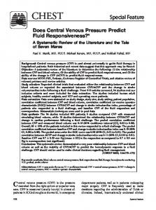
Figure 1. Location of the Soufrière Hills Volcano and extent of survey area (red box).
Figure 2. The volcanic crater and active andesite lava dome (centre) and unstable remnant of older, partially collapsed, lava dome (right).
6
Lee D. Jones
Figure 3. Setting-up the Riegl LPM-2K long range terrestrial laser scanner on Perches survey station.
Figure 4. Contour map (3-D), viewed from the southeast.
7
Lee D. Jones
Figure 5. Surface model (3-D), viewed from the southeast [Surfer™].
Figure 6. Surface model (3-D), viewed from the southeast [GoCAD™].
8