QoS-based Virtual Private Network Design for an MPLS network Anotai Srikitja and David Tipper Dept. of Information Science and Telecommunications University of Pittsburgh 135 N. Bellefield Avenue, Pittsburgh, PA 15260 email:
[email protected],
[email protected] Abstract In this paper, a VPN design model is proposed for the Next Generation Internet (NGI). With the use of MultiProtocol Label Switching (MPLS) in a backbone network, it is possible to create multiple logical sink-trees (directed multipoint-to-point trees ending at one exit node) carrying traffic of multiple VPNs. This makes the VPN design problem with MPLS different from those of circuit-switched networks and connection-oriented packet networks such as ATM. A big question is how to construct a tree and how to incorporate it in the network design model. Here, the VPN design is modeled as a mixed integer programming (InP) optimization problem to minimize the cost of laying out a VPN supporting different traffic types and service classes on a given topology while meeting QoS requirements. Realizing a sink-tree routing path, the proposed model aims to find an optimal VPN layout supporting multi-service classes during different time periods (multi-hour periods) considering that the traffic demand may vary during the course of the day. Our numerical results show that use of sink-tree approach in VPN design can greatly reduce the amount of bandwidth and the number of label switched paths required. I. INTRODUCTION Virtual Private Networks (VPNs) provide a private and dedicated environment over a shared private or public network infrastructure. With the advent of broadband technology, a deployment of QoS-based VPNs supporting integrated service for voice, data and video applications together over public data networks appears to be economically appealing since it allows a high-speed access with performance and Quality of Service (QoS) guarantees. Major challenges in deploying QoS-based VPNs over the Internet are delivering a performance guarantee and security assurance to a degree that is comparable to a real private network. MultiProtocol Label Switching (MPLS) technique proposed by IETF uses a label-swapping forwarding paradigm to expedite a packet-forwarding process [1,2]. MPLS provides a connection-oriented, QoS-based approach to the NGI together with a traditional, connectionless, besteffort approach. Deploying MPLS over a IP network makes it easier for VPN services to provide performance at required levels. Since MPLS is designed to have a traffic engineering capability, provisioning for traffic having different QoS requirements in different Classes of Service (CoS) is possible [3]. In term of security, another no-less important issue, the goal is to protect VPNs data from maliciously or accidentally
misconduct. IP Security Protocol (IPSec) [4] is aimed to be used for this purpose. Using MPLS, multiple VPNs can be constructed on the same network through the use of different MPLS Forward Equivalent Classes (FECs). FEC is used to defined traffic that will be forward in the same manner through a MPLS network. Thus, different FECs will be used to classify traffic from different VPNs which may or may not use the same forwarding path and may or may not share a portion of network bandwidth. The path through an MPLS network can be a multipoint-to-point paths or a sink-tree path ending at one exit node. To guarantee performance to VPN services, a service provider has to be concerned with capacity provisioning and routing coexisting VPNs having different service classes and topologies over the same network infrastructure. In addition, in designing a VPN, one must be concerned with scalability issues in order to support a large number of customers. In another words, a well-designed VPN must be easy to manage and attain bandwidth efficiency. Over a MPLS network, this means that the number of label switched paths (LSPs) and required labels must be kept small. In term of capacity efficiency, different levels of traffic aggregation may be considered, for example, aggregation of traffic from different VPNs belonging to the same CoS, aggregation of traffic from same VPNs exiting at the same egress node, etc. From a design perspective, the concept of a virtual network in general can be applied to VPNs. The notion of virtual networks has long been used to refer to a logical network layout over a network architecture. VPNs over a circuitswitched or an ATM network, are often viewed as a logical mesh network with point-to-point demands between node pairs. A logical full-mesh is a topology where each point-topoint demand pair is independently given a logical link that may be routed over multiple switched-points. The use of sink-tree paths in MPLS makes VPN design problem differ from those in traditional connection-oriented networks previously mentioned. Traffic of different VPNs with the same QoS requirement may/may not be carried on the same routing tree and may/may not share network bandwidth. A big question is how to construct a tree and how to incorporate it in the network design model. Only recently has work appeared on optimization models to solve traffic engineering problems in general over MPLS network. In [5], authors provided integer programming formulations for flow assignment problem given a set of
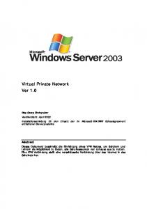
point-to-point LSPs and it can be extended to solve a capacity planning problem. However, several trivial assumptions are made including : (i) one-to-one relationship between traffic trunks and LSPs, (ii) no aggregation, de-aggregation and merging of LSPs. (iii) the model is valid only if one or more feasible solutions exist. [6] proposed the use of multipoint-topoint LSPs in flow assignment problem. A set of pre-selected LSPs is forced to include at least two routes which do not share any single node to each ingress/egress node. The optimization model aims to minimize the maximum link load without considering cost of link capacity. Realizing a sink-tree routing path, this paper proposes mathematical formulations for the problem of VPN design in order to simultaneously find optimal VPNs logical topologies and their dimensions over a service provider IP infrastructure supporting MPLS to carry multi-service, multi-hour VPNs traffic from various customers. Here we exploit pre-computed sink-tree paths (multipoint-to-point paths) over which VPN traffic is routed in a MPLS core network. In the model, different levels of bandwidth aggregation/multiplexing occur across different service classes and routes within one VPN, but not across different VPNs. It is clearly shown that such problem formulations yield a NP-hard complexity. Therefore, preliminary work is conducted for simple cases where only single-service, single-hour VPN traffic is considered. Obtaining the solution to this problem provides a benchmark measure and a guidance to solution feasibility. SINK-TREE LSP PATH As previously mentioned, a label switched path (LSP) in MPLS can be a multipoint-to point path referred in here as a sink-tree path. A clear benefit is its scalability since fewer LSPs must be created compared to using a point-to-point path between each demand pair. The number of labels required is also smaller. Thus, management is simpler. For example, applying a full-mesh design where there is a point-to-point paths between all node-pairs, to a N -node network, the total number of LSPs required is N ⋅( N − 1) . However, this number can be reduced to N paths using a sink-tree design. Figure 1 displays a full-mesh versus sink-tree design for a 3-node VPN over an 8-node MPLS network. Assume that there is a directional demand of one unit between 3-node pairs in VPN network and each link in the MPLS network has one unit cost. A full-mesh design requires 6 LSPs compared to 3 LSPs in sink-tree design. Both designs use the same links in MPLS network. However, the first yields 14 unit cost while, in the latter, the cost is reduced to 12. The cost saving results from the capacity efficiency gain attained, when traffic is merged in a sink-tree design. II.
III. VPN DESIGN METHODOLOGY
The design of VPNs is expected to be a part of the traffic engineering procedure that can be done offline to obtain the VPNs routing plan and virtual network link (VNL) dimension. This is shown in Figure 2. During an operational
Overlay VPN Network
1 1
1 2
2
2 3
5
3
5 6
6
4 4
Service Provider MPLS Network
(a)
Full-Mesh Design 2
2
2 2 1 1 3
1 3
1 3
3
Service Provider MPLS Network
(b) Sink-tree Design
Figure 1 : Full-mesh versus sink-tree design
period, network management will monitor the changes in traffic patterns, network topology or link cost metrics. When it notices any changes that will invalidate the current settings, it will start a global optimization procedure to do an offline recomputation. Note that, the optimization procedure can be done separately for each VPN or jointly for all VPNs to achieve a true optimal solution. For QoS-based VPNs over MPLS, the proposed network design process aims to find the optimal logical sink-tree(s) and its dimension so as to minimize the total network cost while satisfying QoS constraints. Three main tasks are involved in the design process: (i) Tree generation/selection, (ii) Dimensioning and (iii) Routing Optimization. The first task is concerned with generating a candidate set of logical trees for a given source and a set of destinations. The second task is to find a bandwidth that will be allocated to each link in a tree whose bandwidth may/may not be shared by different VPNs traffic. The last task aims to find an optimal route assignment for a given traffic demand. In general, these three main tasks can be solved independently or jointly. The network topology and node locations (e.g. locations of MPLS edge routers and core routers) will be used to generate multipoint-to-point tree paths which are selected based on traffic QoS constraints. For instance, a bound on maximum delay can be translated into a maximum hop limitation. A precomputed path set is used in the optimization model over which the optimal routes and capacity requirements are determined. The bandwidth allocation/dimension of the virtual network should provide sufficient Grade-of-Service (GoS) (e.g., connection blocking probability) and fairness to different services while satisfying several performance
Path Selection Procedure
- Network topology and node locations
Candidate Trees Generation
- QoS constriants (Maximum delay requirement)
Feasible Trees Selection
n
Off-line Global Optimization Procedure
1
3
VPN n
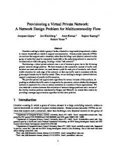
Depth = n-1
VPN 1
Virtual Network Dimensioning - GoS - Packet loss probability
Effective Bandwidth Calculation
Virtual Link Dimensioning Network Route Optimization
Depth = 1
- Traffic demand matrix - Qos
- Link cost matrix
2
3
4
n
(a) Sink-tree with 1-hop depth Change in network topology
VPNs optimal routing plan and Virtual link dimension
Change in link cost
Change in traffic demand
On-line Traffic Optimization and Monitoring
Figure 2 : VPN traffic engineering procedure
constraints at the traffic layer such as packet loss rate and delay. In addition, considering the effects of statistical multiplexing among different connections (when possible), bandwidth allocation can be reduced. Here, we use the concept of “effective bandwidth” to represent service rates required by each traffic connection belonging to different service classes. Effective bandwidth calculations will encapsulate the QoS requirements in term of packet loss rate and delay. Thus, by using the concept of effective bandwidth, traffic flows with different characteristics and QoS requirements can be represented as being steady with a deterministic bandwidth requirement. This simplifies our optimization model. Lastly, the routing optimization will optimally assign a route to a traffic demand, given a set of candidate routes and link capacities. Other than minimizing cost of laying out a given traffic, a route assignment may also aim to balance the load across the network such that the number of over-utilized links and under-utilized link is reduced. IV. TREE SELECTION
The choice of a tree is important as it affects the goodness of the solution obtained and the computation time. To reduce the problem size (and thus computation time) for a large network, a precomputed candidate set of trees will be used in the model over which the optimal routes and capacity requirements are determined. A path set will be generated for each source and its destinations given the physical network topology. This set will be limited by a maximum hop-count allowed between each source-destination pair such that the maximum end-to-end delay is bounded. The choice of a routing tree also affects the capacity required and if bandwidth of traffic flows is aggregated and multiplexed
2
1
(b) Sink-tree with (n-1)-hop depth
Figure 3 : Sink-tree routing paths for n nodes
when they are merged at one node. For connections within the same class of service, in which a statistical multiplexing can be achieved, a certain part of allocated bandwidth can be shared among them. Hence, in tree selection, there is a trade off, between minimizing an end-to-end delay requirement versus minimizing cost of link capacity. Shown in Figure 3 are two different choices of a sink-tree for n nodes. The depth of a tree is defined as the distance between the root node and a leave node. Figure 3(a) show a sink-tree of 1-hop paths with a maximum depth of 1. This choice of a tree yields a minimum delay between demand node-pairs, but, since 1-hop paths merge at the root node, no bandwidth aggregation is possible. Oppositely, the tree in Figure 3(b) with a depth of (n-1) yields a maximum bandwidth gain due to statistical multiplexing at all links after the merge points. Different types of trees including spanning trees, shortest (distance) path trees and Steiner trees (minimum-cost trees) are among potential choices. V. MPLS-VPN DESIGN FORMULATIONS Given a network topology, node location and link capacity, an optimization model is formulated for VPN design. A physical network is represented by a graph G (N , L, C ) where N , L , C is a set of nodes, links and link capacities of the network respectively. M ( M ⊂ N ) is a set of edge nodes (edge routers) where there is a demand traffic entering or exiting. Thus, N − M represents a set of core nodes (core routers). The complete notation of the formulation is given below. For each link l ∈ L , utilization factor α l limits the
proportion of the link capacity
Cl
to be allocated for VPN
traffic. This utilization factor may be used to protect certain links from being overly subscribed or subjected to potential congestion. For example, a smaller value of α l may be assigned to links connecting to core-routers than ones connecting to edge-routers. This factor is assumed to be known.
A. Notation αl Maximum utilization factor of link
C. Selection of Candidate Paths Feasible sink-trees or multipoint-to-point paths are used in the optimization model where a traffic demand may be assigned. The feasible path set Pkν , s can be pre-computed for
l∈L
Pν , s
Demand set index, K ⊂ M Set of feasible sink-trees ending at node
Dν , s, k
spanning all nodes m ∈ M of service class s ∈ S of VPN ν ∈V Set of point-to-point demand pairs in demand set
K k
k∈K
Bνd, h, s, k
of service class
s∈S
of VPN ν ∈V
Bandwidth requirement of demand pair service class
s∈S
k∈N
d ∈ Dν , s, k
of
of VPN ν ∈ V during hour-period
h∈H Yl
Sizing (topology) variables, capacity assigned to
ψl
VPN traffic on link l ∈ L Cost of a capacity on link
l
Capacity at link
Uν , h
hour-period p
X ν , h, s , k
l∈L
l∈L
allocated to VPN ν ∈ V during
h∈H
Demand-path routing decision variables =1
γ lp, d
if path
p ∈ Pkν , s
k∈K
of service class s ∈ S of VPN ν ∈ V during hour period h ∈ H = 0 otherwise Link path incidence matrix =1
if demand pair uses path
EBνl , h, s, k
is used for demand set
d ∈ Dν , s, k
p ∈ Pkν , s
of set
k∈K
that
is directed using link
l∈L
=0 otherwise Estimated BW requirement of all demand type
VPN ν and service class s having different QoS requirements (i.e., maximum end-to-end delay requirement). A path p ∈ Pkν , s is selected from candidate sink-tree paths which are spanning trees rooted at egress node k ∈ K and spanning over all the edge nodes m ∈ M or a subset of the edge nodes. Set of candidate paths can be generated by enumerating all distinctive spanning trees. Algorithms to determine these trees can be found in previous works including [7]. The maximum end-to-end delay requirement is translated in to the hop-count limitation constraint. This constraint will limit the path set where only feasible paths are selected from all candidate paths. D. Bandwidth Calculation The bandwidth requirements at each link will be estimated based on an effective bandwidth calculation [8] where the traffic parameters such as connection peak rate and its burstiness are taken into account. Two classes of services in a differentiated service model are considered including premium/guarantee service and assured services. ( i ) Premium Service In the premium service class, packet loss, delay and delay jitter must be bounded. The traffic of this class requires an absolute bandwidth guarantee. Thus each traffic connection in this class is allocated a bandwidth equal to a source peak rate R peak . Assuming that η connections are multiplexed within one link, total allocated bandwidth ( Eqv )
on link l ∈ L of service class s ∈ S of VPN ν ∈ V during hour-period h ∈ H ) Equivalent bandwidth calculation function for traffic in service class s ∈ S with requirement of bandwidth amount B ( with traffic descriptor Ts and quality of service requirement Qs )
where η is derived from an inverse Erlang formulation such that a grade of service constraint (GoS) of a connection (i.e., connection blocking probability - P b ) is met.
B. Traffic Demand The complete matrix of VPNs traffic demand is assumed to be given. It can be derived from all SLAs (Service Level Agreements), between customers and service providers. SLAs typically specify various classes of service and how much traffic in each service class a user is allowed to send. In more detail, for each source-destination (ingress-egress) node-pair, the matrix of each VPN specifies the required bandwidth and its QoS parameters (i.e., end-to-end delay requirement, delay jitter). Traffic demand Dν , s, k will be
( ii ) Assured Service In the assured service class, applications are expected to have the ability to tolerate a certain amount of delay and loss. For this traffic class, a mean bandwidth guarantee is only needed along with a statistical delay bound. In bandwidth calculation, source traffic in the assured service class is assumed to be characterized by its source peak rate - R peak ,
k∈K
Eqv(B, Ts , Qs
assigned a route based on its egress node where K ⊂ M , called the demand set index.
k∈K
,
Eqv
(1)
= η ⋅ R peak
(2)
η = InvErlang ( a, Pb )
where a is the source utilization or an offered load of a connection.
utilization factor - ρ , and mean burst period - b . In this case, the allocated bandwidth ( Eqv ) is less than η ⋅ R peak .
{
Eqv = min η ⋅ m + α ′σ ,
η ⋅ cˆi
}
(3)
where α ′ = − 2 ln(ε ) − ln(2π ) given m − a mean bit rate, σ − a variance bit rate, and ε − buffer overflow probability. Equivalent capacity estimation for each source cˆi is cˆi
= R peak
(a − 1)2 + 4 ρ a
a − 1+
(4)
2a
=
−
traffic demand pair
Dν , s, k
and bandwidth requirement
, (iii) a precomputed sink-tree path set
corresponding link path incidence matrix
ν,s
and a
γ lp, d .
The
Pk
formulation seeks to find VPN link capacity allocation and its route
p
X ν , h, s , k
Uνl , h
for all VPNs in each hour period.
Formulation-I shows the case where there is no bandwidth aggregation. The objective of the formulation is to minimize the total capacity cost in providing service to all VPNs. For each VPN, service class, and hour period, constraint (5) selects only one path from a pre-computed set of feasible sink-tree paths ending at egress node Pk for each demand set k . Constraints (6) − (9) imposes that capacity assigned at each link must not be greater than a utilization limit of link capacity ( α l ⋅ Cl ). Note that, in constraint (6), the capacity calculation is done separately for each traffic demand-pair. Constraints (10) and (11) require that routing variables and capacity assignment variables must be positive. This formulation yields different route assignment and capacity allocation at different hour-periods. Formulation-I Minimize
∑ ψ l ∗ Yl
∑
EBν , h, s, k
∑
ν ∈V
,
s∈S
h∈H
,
l∈L
Xνp, h, s, k
,
l∈L
(6)
(7) l∈L
;∀: l∈L
(8) (9)
{0, 1} ; ∀ : ν ∈V ,
h∈H
,
s∈S
,
k∈K
,
p ∈ Pkν , s
;∀: l∈L
≥ 0
Yl
k∈K
;∀ : h∈H ,
≤ Yl
∈
,
≤ Uν , h
≤ α l ⋅ Cl
Yl
(10) (11)
F. General Case with Bandwidth Aggregation. Here, we introduce a case where bandwidth of various traffic demand is aggregated at links where possible. The aggregation only occurs within a demand set destined to the same egress node of a VPN. In this case, the objective function and constraints are similar to previous case except for constraint (6) is replaced by (12). The total traffic demand routed on one link is aggregated and bandwidth allocation is done together. Formulation-II Minimize
∑ ψ l ∗ Yl
l ∈L
Subject to :
(5), (7), (8), (9), (10), (11), and EBνl , h, s, k = Eqv ∑ Bνd, h, s, k ∗ ∑ γ lp, d ∗ Xνp, h, s, k , Ts , Qs d ∈D p∈Pν , s ν , s, k k
∀ : ν ∈V , h ∈ H , s ∈ S , k ∈ K , l ∈ L
(12)
PRELIMINARY NUMERICAL STUDY The mixed-integer formulations for the VPN design problem, shown previously, have a NP-hard complexity. A simplified version of these formulations can be derived when we only consider traffic demand of VPNs having one service class and hour-period. Thus, the formulation-I can be reduced to: VI.
Formulation-III Minimize
∑
p∈Pk
= 1
; ∀ : ν ∈V ,
Uνl , h
h∈H
l
∑ ψ l ∗ Yl
Subject to :
Subject to :
∑
; ∀ : ν ∈V ,
l ∈L
l ∈L
p X ν , h, s , k
∑
; ∀ : ν ∈V ,
E. General Case without Bandwidth Aggregation Using a sink-tree routing path, traffic demand can be merged within the network, thus the required bandwidth after the merged point can be allocated separately for each demand-pair or multiplexed together within the same service class. The latter yields a reduction in bandwidth requirements especially for traffic in the assured service class, due to a statistical multiplexing gain. The basic formulations are given below. The model assumes that the followings are given: (i) link utilization factor α l and the link capacity Cl , (ii) set of
p∈Pν , s k
∑
l
b (1 − ρ ) ln ε B
assume that B − buffer size and ε − packet loss ratio are known. The number of connections η multiplexed can be found as before from an inverse Erlang formulation.
Bνd, h, s, k
p d l ∗ Eqv Bν, , T , Q γ X ∗ ∑ h, s, k s s p, d ν, h, s, k p∈Pν,s d ∈Dν, s, k k
s∈S k∈K
where a
l EBν, = h, s, k
h∈H
,
s∈S
,
k∈K
(5)
X kp
= 1
; ∀ : k∈K
(13)
Eqv Bkd , T , Q ∗ ∑ γ lp, d ∗ X kp ≤ Yl k ∈ K d ∈Dk p∈Pk
∑
)
≤ α l ⋅ Cl
Yl p
Xk Yl
(
∑
∈
{0, 1}
≥ 0
;∀: l∈L ;∀: l∈L
(14) (15)
; ∀ : k ∈ K , p ∈ Pk
(16)
;∀: l∈L
(17)
(a) 8-node network
In the same manner, the formulation-II can be reduced to : Formulation-IV Minimize
∑ ψ l ∗ Yl
l ∈L
Subject to :
(13), (15), (16), (17), and d l p Eqv B ∗ γ ∗ X , T , Q ∑ ∑ p, d ∑ k ≤ Yl k d ∈Dk k∈K p∈Pk
;∀: l∈L
(18)
Obtaining a solution to problems stated in formulation-III and IV is easier than ones in formulation-I and II. A pilot study was conducted by translating formulation-III and IV using the AMPL model description language and solution is obtained using CPLEX 6.6 optimization solver implementing a branch and bound solution technique. The networks studied were small networks with 8 and 10 nodes, with equal capacity link-cost, shown in Figure 4. The capacity of each link Cl was set to Cl = 1000 ; ∀l ∈ L , so that capacity was not a limiting factor. Different cases are shown in Table 1. For case-I, asymmetric load of fixed demands was studied that is there was one unit of demand from each node to every other node. For case-II, a symmetric load of demand was considered with the demand generated from a Uniform(1,5) distribution. For case-III, an asymmetric load of demand was studied with nonzero demand only from a subset of network nodes. The nodes with nonzero demand were randomly selected with a random load drawn from a Uniform(1,5) distribution. From Table 1, one can see that the optimal solutions obtained from a sink-tree design with no bandwidth aggregation are not different from ones obtained from a fullmesh design. It is observed that a path used in a sink-tree design (with no bandwidth aggregation) is simply a shortestpath tree. This is similar to a full-mesh design where a demand is routed along a shortest path. In terms of cost, when bandwidth aggregation is considered in a sink-tree design, a cost reduction is realized approximately by 30-40 percent in all cases. This is because traffic demand may be routed using a sink-tree path that is different from a shortest path tree. Note that there is a huge difference in the number of LSPs used between the sink-tree and full-mesh design approaches. In order to obtain a solution to general case problem, where multi-service and multi-hour period are considered, and where multiple VPNs layouts are simultaneously
(b) 10-node network
Figure 4 : Networks under study
optimized, one seeks to find more efficient solution method due to the problem complexity. Results from the pilot study suggest that a heuristics method may start out its search from a so-called near-optimal solution obtained by routing demand traffic using shortest-path trees, then seek out a better solution as it moves along a projected direction within a feasible search space. One may apply various heuristics techniques explored in the literature, such as greedy algorithm, simulated annealing, or genetic algorithm, to solve this problem. VII. CONCLUSION In this paper we have formulated the MPLS based multihour VPN design problem with and without bandwidth aggregation. We modeled a VPN as multiple logical sink trees which reduces the number of label switch paths and allows the possibility of bandwidth savings. Sample numerical results for different studied cases shows that a sink-tree design with no bandwidth aggregation yields the same solution as a full-mesh design where demand was routed along a shortest-path. However, when bandwidth aggregation is considered in a sink-tree design, demand was routed along a tree that is different from a shortest-path tree such that a link capacity assignment can be smaller and the total capacity cost reduction is realized.
[1] [2] [3] [4] [5]
REFERENCES E. Rosen, A. Viswanathan, and R. Callon, "Multiprotocol Label Switching Architecture," RFC 3031, January, 2001. B. Davie and Y. Rekhter, MPLS : technology and applications, San Francisco: Morgan Kaufmann Publishers, 2000. D. Awduche, et al., "Requirements for Traffic Engineering Over MPLS," RFC 2702, September, 1999. S. Kent and R. Atkinson, "Security architecture for the Internet Protocol," RFC 2401, November, 1998. K. M. Girish, B. Zhou, and J.-Q. Hu, "Formulation of the Traffic Engineering Problems in MPLS based IP Networks," Proceedings ISCC 2000. Fifth IEEE Symposium on Computers and Communications. , Los Alamitos, CA, USA, pp. 214-219, 2000.
[6] H. Saito, Y. Miyao, and M. Yoshida, "Traffic Engineering using Multiple multipoint-to-point LSPs," IEEE INFOCOM 2000, pp. 894-901, March, 2000. [7] N. Christofides, Graph Theory and Algorithmic Approach, London: Academic Press Inc., 1986.
Full-Mesh Design Topology
Optimal Cost
Simplex Iterations
No. of LSPs
[8] R. Guerin, H. Ahmadi, and M. Naghshineh, "Equivalent Capacity and Its Application to Bandwidth Allocationin High-Speed Networks," 7th ITC Seminar, Morristown, NJ, October, 1990.
Sink-Tree(s) Design (w/o BW aggregation) Optimal Simplex No. of Cost Iterations LSPs
Sink-Tree(s) Design (with BW aggregation) Optimal Simplex No. of Cost Iterations LSPs
Case I : Symmetric fixed-load 8-node
104
54
56
104
241
8
56
473
8
10-node
174
162
90
174
308
10
90
925
10
Case II : Symmetric variable-load 8-node
346
64
56
346
99
8
203
2,016
8
10-node
562
112
90
562
242
10
410
4,239
10
Case III : Asymmetric variable-load 8-node
166
42
33
166
101
7
105
319
7
10-node
212
76
35
212
216
7
129
565
7
Table 1 : Comparison for different design cases