Home
Search
Collections
Journals
About
Contact us
My IOPscience
Quality assurance and functionality tests on electrical components during the ATLAS IBL production
This content has been downloaded from IOPscience. Please scroll down to see the full text. 2014 JINST 9 C01046 (http://iopscience.iop.org/1748-0221/9/01/C01046) View the table of contents for this issue, or go to the journal homepage for more
Download details: IP Address: 107.175.212.39 This content was downloaded on 19/01/2016 at 13:28
Please note that terms and conditions apply.
P UBLISHED BY IOP P UBLISHING FOR S ISSA M EDIALAB R ECEIVED: November 15, 2013 ACCEPTED: December 13, 2013 P UBLISHED: January 23, 2014
TOPICAL W ORKSHOP ON E LECTRONICS 23–27 S EPTEMBER 2013, P ERUGIA , I TALY
FOR
PARTICLE P HYSICS 2013,
A. Bassalat1 Le Laboratoire de l’Acc´el´erateur Lin´eaire (LAL), Orsay, France
E-mail:
[email protected] A BSTRACT: During the shutdown of 2013–2014, for the enhancement of the current ATLAS Pixel Detector, a fourth layer (Insertable B Layer, IBL) is being built and will be installed between the innermost layer and a new beam pipe. A new generation of readout chip has been developed, and two different sensor designs, a rather conventional planar and a 3D design, have been bump bonded to the Front Ends. Additionally, new staves and module flex circuits have been developed. A production QA test bench was therefore established to test all production staves before integration with the new beam pipe. Quality assurance measurements under cleanroom conditions, including temperature and humidity control, are being performed on the individual components during the various production steps of the IBL; namely, connectivity tests, electrical tests and signal probing on individual parts and assembled subsystems. This paper discusses the pre-assembly QC procedures, the capabilities of the stave qualification setup, and recent results from stave testing. K EYWORDS : Solid state detectors; Hybrid detectors; Manufacturing; Front-end electronics for detector readout
1 On
behalf of the ATLAS collaboration.
c CERN 2014 for the benefit of the ATLAS collaboration, published under the terms
of the Creative Commons Attribution 3.0 License by IOP Publishing Ltd and Sissa Medialab srl. Any further distribution of this work must maintain attribution to the author(s) and the published article’s title, journal citation and DOI.
doi:10.1088/1748-0221/9/01/C01046
2014 JINST 9 C01046
Quality assurance and functionality tests on electrical components during the ATLAS IBL production
Contents Introduction
1
2
Motivation
1
3
IBL and stave characteristics
2
4
Quality assurance and functionality tests 4.1 Module loading and stave quality control (QC) at the loading site 4.2 Stave QA and selection at CERN
2 2 3
5
Bad pixels identification
4
6
Stave ranking and selection
5
7
Conclusion
6
1
Introduction
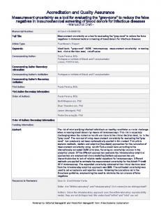
The Large Hadron Collider (LHC) is the largest particle accelerator in the world. ATLAS detector [1] is one of the main four experiments and one of the two general purpose detectors of the LHC. The Inner Detector, a subsystem of ATLAS Detector, comprises the Pixel Detector, the SemiConductor Tracker (SCT) and Transition Radiation Track (TRT). The Pixel Detector is closest to the interaction point, being the most sensitive tracker, and has three pixel layers with 80 million readout channels used to identify and to reconstruct the primary and secondary vertices and also to track the charged particles to make a measurement of momentum. Several upgrades are planned for the LHC operating at high luminosity. Upgrade of the Pixel Detector is underway during the current LHC shutdown, to deal with the high track multiplicity and harsh radiation environment. A new fourth layer of pixels, the Insertable B-Layer (IBL) [2], is planned to be installed by mid-2014 between the existing pixel system and a new beam pipe with a reduced diameter (of 29 mm) as shown in figure 1.
2
Motivation
The principal motivation for the IBL is to provide improved tracking robustness in order to maintain excellent reconstruction efficiency in the foreseen high luminosity environment [3]. The IBL requires the development of several new technologies to cope with increased radiation and pixel occupancy. Reducing the pixel size will improve the physics performance as the instantaneous luminosity of the LHC increases beyond the design luminosity of 10−34 cm−2 s−1 .
–1–
2014 JINST 9 C01046
1
Table 1. General IBL characteristics.
3
Layout
14 staves
Number of modules
280
Type of modules
Planar silicon + 3D silicon
Number of pixels
12 million
Active length
64 cm
Mean active geometric radius
33.4 mm [3]
Number of IBL pixels/number of pixels in Pixel Detector
15%
IBL and stave characteristics
The IBL provides a significant upgrade of the Inner Detector, as shown by the main characteristics listed in table 1. The IBL will be made of 14 staves. All staves are tilted at 14◦ to the new beam pipe. Each stave consists of 20 modules [3], with 12 modules made of planar sensors bump bonded to 24 Front End (FEI4) [4] (each module is bump bonded to two FEI4) to cover the central part of the stave. Both ends of the stave have the 3D sensors bump bonded to 8 FEI4 (each modules is bump bonded to one FEI4) as shown in figure 2. The FEI4 [2] was fabricated with 130 nm CMOS technology [4], to improve the performance and the radiation hardness of the present Front End chip.
4 4.1
Quality assurance and functionality tests Module loading and stave quality control (QC) at the loading site
After the modules are received from the production sites, they are fully tested at the loading site where modules are selected based on the breakdown voltages and the number of bad pixels per module as shown in table 2. Figure 3 shows the number of bad pixels per module, where only two modules do not satisfy the IBL requirements as listed in table 2. Up to 270 (1%) bad pixels per FEI4 were accepted for the first two staves due to lack of modules.
–2–
2014 JINST 9 C01046
Figure 1. Drawing of the IBL inside the Inner Detector.
Figure 3. Distribution of the number of bad pixels per module. More than 99% of the modules have less than 0.35% bad pixels. Table 2. First selection criteria — modules.
Criteria for the first selection — modules Number of bad pixels < 0.35% (100 pixel/FEI4) Breakdown voltage > 120 V for planar and 80 V for 3D
4.2
Stave QA and selection at CERN
After the staves arrive at the cleanroom at CERN, they are fully tested, then ranked based on criteria listed in table 3 in preparation for the decision to choose the highest quality staves for inclusion in the IBL. The stave QA setup allows to test two staves in parallel. It uses CO2 cooling to achieve −35◦ C. Using a linear motor, an automatic long source scan is performed using radioactive elements, Am241 and Sr91 , figure 4. Within the two weeks of stave QA, burning tests are also completed to analyze the stave performance by using cosmic rays for a few days and tuning the
–3–
2014 JINST 9 C01046
Figure 2. Schematic view for the stave (middle) with planar modules in the central region (right) and 3D modules in the forward region (left).
Table 3. Second selection criteria — staves.
Criteria for the second selection — stave Number of bad pixels < 0.35% (100 pixel/FEI4) Tunable at low threshold, no noisy pixels (less than 100 noisy pixel) staves is performed for different threshold values (3000 electron (e) to 1500 e) at the real operational temperature of ATLAS around −15◦ C and −20◦ C. In addition to the burning tests, the main functionality tests include: • connectivity tests, power cycling, and IV curves for sensor characterization; • basic FEI4 operational tests (digital and analog) followed by threshold scan, noise scan and cross talk scan for identification the bad pixels for each module and each stave; • detailed tuning in cold and warm temperatures for different threshold values (3000 e to 1500 e); • long source scan using Am241 and Sr91 , as shown in figure 5 and burning tests with cosmic rays for few days and nights; • stave selection and rating based on table 3.
5
Bad pixels identification
Bad pixels are categorized according to seven definitions as listed in table 4. The fault causing a pixel to be classified as bad mainly was due to the chip electronics or problems in the bump bonding
–4–
2014 JINST 9 C01046
Figure 4. The stave QA setup in SR1. It allows to test two staves in parallel.
Table 4. Main bad pixels classes found in the staves tested and qualified at CERN up to this point.
The bad pixels type
The definition
Dead digital pixel
Some failure in the digital part of the FE
Dead analog pixel
Some failure in the analogue part of the FE
Disconnected bumps
No contact between sensor and electronics
Merged bumps
Neighboring bumps are connected together
Noisy pixels
Pixels show too many noisy hits
Non-tunable pixel
Pixels can not be tuned
Extra Xtalk pixel
Pixels show high X-talk
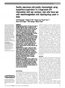
between the sensor and chip electronics. The method used to identify the bad pixels in each stave during the QA is described in figure 6. The ratio plot shows that the dead digital pixels contribute only a small fraction of the total bad pixels in each module, while between 40% and 45% of the bad pixels were due to disconnected bumps, as shown in figure 7. Regardless of the type of bad pixels, modules with more than 0.4% bad pixels were rejected, corresponding to 100 bad pixels in FEI4, 200 pixels in the planar modules and 100 pixels in the 3D modules.
6
Stave ranking and selection
From all the staves produced, the highest quality 14 staves will be chosen based on the ranking attributed to each stave. The number of bad pixels is one of the main factors to make this ranking. Figure 8 shows the good quality of the staves already tested, since the IBL requires the number of bad pixels to be less than 0.35%.
–5–
2014 JINST 9 C01046
Figure 5. Stave 08 occupancy from Am241 source scan. The scan was performed at −20◦ C.
Figure 7. The ratio of bad pixels in each class. Approximately 45% of the total number of bad pixels are due to disconnected bumps.
7
Conclusion
Detailed QA has been carried out for all modules that were loaded into the staves in order to select the highest quality modules. QA has been carried out on the first seven staves at CERN, at time of writing, to evaluate the quality of each stave. Pixels with failure in FEI4 and in bump bonding were
–6–
2014 JINST 9 C01046
Figure 6. The method used to identify the bad pixels in each stave during QA.
assigned as being bad pixels, all modules with < 0.35% of bad pixels were considered for the IBL. The staves are selected based on table 3 and figure 8. The seven tested staves can be considered as good candidates for IBL, unless unexpected problems are found.
References [1] ATLAS collaboration, The ATLAS experiment at the CERN Large Hadron Collider, 2008 JINST 3 S08003. [2] ATLAS collaboration, ATLAS insertable B-layer technical design report, Technical Report CERN-LHCC-2010-013, ATLAS-TDR-019, CERN, Geneva Switzerland (2010). [3] ATLAS IBL collaboration, Prototype ATLAS IBL modules using the FE-I4A front-end readout chip, 2012 JINST 7 P11010 [arXiv:1209.1906]. [4] FE-I4 collaboration, The FE-I4A integrated circuit guide, V.11.2 (2011).
–7–
2014 JINST 9 C01046
Figure 8. The total number of bad pixels in each stave tested in SR1 (red), and the number of noisy pixels at low threshold tuning (blue).