Mar 10, 2014 - FÃsica Aplicada, Universitat Politècnica de València, Camino de Vera s/n, ... 2Centro de TecnologÃas FÃsicas: Acústica, Materiales y AstrofÃsica, ...
Applied Physics Express 7, 042201 (2014) http://dx.doi.org/10.7567/APEX.7.042201
Quantitative characterization of bandgap properties of sets of isolated acoustic scatterers arranged using fractal geometries Sergio Castiñeira-Ibáñez1, Constanza Rubio2, Javier Redondo3, and Juan Vicente Sánchez-Pérez2* 1
Dpto. Física Aplicada, Universitat Politècnica de València, Camino de Vera s/n, 46022 Valencia, Spain Centro de Tecnologías Físicas: Acústica, Materiales y Astrofísica, Universitat Politècnica de València, Camino de Vera s/n, 46022 Valencia, Spain 3 Paranimf 1, 46730 Gandia, Universitat Politècnica de València, Valencia, Spain E-mail: jusanc@fis.upv.es 2
Received January 9, 2014; accepted February 15, 2014; published online March 10, 2014 The improvement in the bandgap properties of a set of acoustic scatterers arranged according to a fractal geometry is theoretically quantified in this work using the multiple scattering theory. The analysis considers the growth process of two different arrangements of rigid cylinders in air created from a starting cluster: a classical triangular crystalline array and an arrangement of cylinders based on a fractal geometry called a Sierpinski triangle. The obtained results, which are experimentally validated, show a dramatic increase in the size of the bandgap when the fractal geometry is used. © 2014 The Japan Society of Applied Physics
he emergence of artificial periodic systems as devices capable of controlling the propagation of wave fields, such as electromagnetic or elastic fields, has attracted considerable interest during the last decade. The peculiar behavior of waves when they are transmitted through these periodic materials, which are generally known as wave crystals, is caused by the existence of bandgaps (BGs).1,2) These BGs can be defined as ranges of frequencies, related to the geometrical properties of the crystals, where the transmission of waves is forbidden.3) Destructive Bragg interference due to a multiple scattering process is the physical mechanism of this attenuation phenomenon. In acoustics, where the periodic systems are generically called phononic crystals, the BG properties have been used to design several control devices.4–7) However, the creation of large attenuation bands by means of Bragg interference, which is necessary to design devices that are competitive with others based on different physical principles, is not easy owing to the high number of parameters involved in the formation of the BGs. Two ways of enhancing the BG properties have traditionally been considered. On the one hand, the possibility of designing scatterers including new control mechanisms has been developed. In this sense, some research in the field of environmental acoustics has proposed the construction of mixed scatterers in such a way that Bragg interference is not the only mechanism involved in the creation of wide attenuation bands. Thus, absorption or resonances are included in the design of these scatterers.8) On the other hand, the possibility of obtaining new arrangements of scatterers unlike the crystalline ones and with high performance in BG creation has also been explored. Thus, the use of quasicrystals,9) quasiordered structures,10) or even amorphous structures based on the concept of hyperuniformity11) in different types of wave crystals has been analyzed. Joining both lines of research, acoustic barriers with high noise control capabilities due to the existence of wide attenuation bands have been designed, constructed, and homologated.12) Following this second line of research, some authors have analyzed the possibility of using fractal geometries in the design of wave crystals to obtain large BGs.13) Fractal geometries have been used successfully by either adapting the shape of the scatterers14) or designing new arrays of scatterers in which the increase in the size of the BG is due to the coexistence of several identical arrays with a different
T
lattice constant, one within the other.15) In this last case, the resultant arrangements are usually called quasifractal structures because only a few levels of the fractal geometry are achieved, although the fractal construction follows an infinite iterative process. Nevertheless, even though it has been qualitatively demonstrated that the size of the BG increases when the scatterers are arranged following a quasifractal geometry, it seems technologically interesting to quantify this improvement in order to examine the real possibilities of using these geometries to design technologically advanced devices based on arrangements of isolated scatterers. According to this last argument, in this work we present an experimentally verified theoretical study devoted to quantifying the enhancement in the BG properties of a set of rigid isolated scatterers arranged according to a two-dimensional fractal geometry. To properly organize the study, we followed two steps. First, we measured the variations in the BG properties throughout the growth process of a quasifractal structure created from the smallest possible starting cluster. In this growth process, the starting cluster is repeated as many times as necessary according to the fractal geometry selected. In this process, only translations of the starting cluster are needed to create the quasifractal pattern. In the second step, we repeated the growth process but arranged the scatterers according to a classical crystalline pattern. In this case, the typical translations and rotations of the starting cluster necessary in crystalline growth were used. The growth processes were interrupted at the fourth level in such a way that the highest samples can be analyzed according to our computational and experimental capabilities. Finally, we quantitatively compared the BG properties of the quasifractal and crystalline samples. We took into account that the samples with the same level of growth in both cases (quasifractal and crystalline) must have the same external shape and size in order to compare their BG properties, where the number of scatterers and their arrangement were the only differences allowed. Although this study and the obtained results can be applied to any type of wave field in ranges of frequencies where the physics of the process is linear, we worked with a particular type of phononic crystal called a sonic crystal,16,17) which is formed of rigid cylinders acting as scatterers in air. These two-dimensional arrays of scatterers are widely used in research for several reasons, such as their simplicity, their size, and the high symmetry of the cylinders, which provide a
042201-1
© 2014 The Japan Society of Applied Physics
Appl. Phys. Express 7, 042201 (2014)
(a)
S. Castiñeira-Ibáñez et al.
cluster a r a
Sierpinski triangle (b)
S
1m
Quasifractal arrangement 1m R
YX
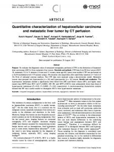
Fig. 1. (a) Sierpinski triangle fractal geometry up to fifth level with cross-sectional view of largest quasifractal arrangement of cylinders considered (fourth fractal level). Picture shows experimental sample used in the measurements. Inset shows starting cluster. (b) Comparison of IL spectra obtained theoretically by multiple scattering simulations (solid red line) and experimentally (dashed black line). Inset shows setup used.
low computational cost in theoretical simulations. Thus, we chose a starting cluster formed of three aluminum cylinders with a radius of 0.02 m and a length of 1 m as the scatterers. These cylinders are arranged according to a triangular pattern with a lattice constant a = 0.0635 m. We chose this pattern because, among all the crystal lattices, it presents the largest BG owing to its degree of hyperuniformity.11,15) The inset of Fig. 1(a) shows a cross-sectional view of the cluster. From this cluster, we grew a classical crystalline array following a triangular pattern. On the other hand, the quasifractal structure was grown according to a fractal geometry called the Sierpinski triangle, which has been successfully used in other works.15) The shape of this fractal is shown in Fig. 1(a); its geometry is obtained by removing triangles of different sizes from the starting triangle, bearing in mind that the fractal level increases as the removed triangles become smaller. Here the fifth level is shown. Note that the shape of each part of the fractal is always the same as that of the whole, which is an important property of fractal symmetries. In addition to this shape, in Fig. 1(a) we also show the quasifractal structure formed from the starting cluster and a picture of the experimental sample constructed to validate the theoretical results, which rises to the fourth level. The calculations were implemented using the well-known multiple scattering theory.18–22) This analytical self-consistent method is used to obtain the scattered field of arrays of isolated scatterers considering all the orders of scattering, and consists of solving the following infinite system of linear equations: N q¼1 X X Als � tjs Ajq �ljsq ¼ tls Sls ; ð1Þ j¼1 q¼�1
where Als represents the coefficients of the series of Hankel functions that characterize the scattered waves. With this methodology, the acoustic pressure at the target point (x, y) for a distribution of cylinders at the frequency ¯ can be expressed as N sX ¼1 X pð�; x; y; kÞ ¼ p inc þ Als Hls ðkrl Þeð�s�l Þ ; ð2Þ l¼1 s¼�1
where k is the wave number (k ¼ 2��=c), p inc ¼ P s �s� is the incident plane wave, ðr; �Þ are the polar s � Js ðkrÞe coordinates of the point ðx; yÞ, and ðrl ; �l Þ are the polar coordinates of the point ðx; yÞ with respect to the cylinder l. In this work, the attenuation properties are represented using the insertion loss (IL), which is defined as IL ¼ 20 log
jp inc j : jpj
ð3Þ
To quantify the attenuation properties of the considered samples, we used the attenuation area (AA) parameter in the analyzed range of frequencies (0–6500 Hz) and along the OX axis (¥X direction of the sonic crystal). The AA parameter has been used successfully in previous works related to sets of isolated cylinders in air10,15) and can be defined as the area enclosed between the positive IL spectra and the 0 dB threshold in the selected frequency range. The experiments for ascertaining the validity of the analytical results were conducted in an anechoic chamber 8 © 6 © 3 m3 in size. We obtained the pressure pattern at a point located 1 m behind the sample according to the scheme shown in the inset of Fig. 1(b), using a prepolarized freefield 1/2″ microphone (B&K 4189) and a sound source (GENELEC 8040A) emitting continuous white noise. The
042201-2
© 2014 The Japan Society of Applied Physics
Appl. Phys. Express 7, 042201 (2014)
S. Castiñeira-Ibáñez et al.
FS4 TS1
TS2
243 cyl.
TS3
Cry st tran al-Frac sitio tal n
FS3
CS4
Fra
528 cyl. 2 A=174,5cm
cta row
lg FS2
Crystalline growth
th
CS3
Fractal samples (FS)
A=86,5cm
2
CS2
2
A=42,5cm
CS1
FS1 Starting cluster
Transition samples (TS) Crystalline samples (CS)
2
A=20,5cm
(%)
Fig. 2. Attenuation capabilities vs filling fraction of crystalline (red squares connected by solid black line) and quasifractal (blue circles connected by dotted black line) growth processes. Steps in creation of largest quasifractal structure (FS4) from a complete crystalline sample of equal size (CS4) are also shown (green pentagons connected by dashed black line). Cross-sectional views of each sample with its main characteristics, including the starting cluster, are also shown.
frequency response of the sample was recorded from the Fourier transform of the temporal signal obtained by the microphone. The samples were constructed by hanging the aluminum cylindrical scatterers on a periodic frame with triangular symmetry, as shown in the picture in Fig. 1(a). In Fig. 1(b), we compare the experimental and theoretical IL spectra. The results exhibit fairly good agreement, so we can validate the theoretical model used. To analyze the attenuation capabilities of the samples, in Fig. 2 we show their AAs as a function of the filling fraction (ff ). To compare properly the BG results for both types of samples, the crystalline ones have been grown with an external triangular shape, as the quasi fractal ones have due to the fractal geometry used. Note that, at each level of growth, the area occupied by both types of samples is the same. Thus, the couples CS1–FS1, CS2–FS2, CS3–FS3, and CS4–FS4 have equal areas, which are greater when the level of growth (1, 2, 3, and 4 in ascending order) is higher. The numerical values of these areas are shown in Fig. 2 below the crosssectional view of each crystalline sample. To represent the growth patterns of the samples, in all cases we used the ff of the entire samples, defined as the sum of the areas of all the cylinders forming each sample divided by the total area occupied by the sample. This definition differs from the classical ff definition, but here it seems necessary because the rules of the crystalline state are not fulfilled for the fractal geometries. Nevertheless, this definition allows us to determine the area occupied by the cylinders that form each
sample divided by the total area occupied by the sample in the quasifractal cases, and coincides with the classical definition of the ff used for crystalline arrangements. Figure 2 shows both types of growth on the main graph. On the right, the growth pattern of the crystalline samples (squares connected by a solid black line) is shown. In this case, the ff remains constant throughout the growth process, ff = 36%, whereas the AA increases at the same time as the area of the samples increases, which is typical behavior in crystalline growth. Thus, the largest crystalline sample (CS4) is formed by 528 cylinders occupying an area of A = 174.5 cm2, with an AA value of 39.580 Hz0dB. On the other hand, on the left, one can observe the growth pattern of the quasifractal samples (circles connected by a dotted black line). As an aid to correct understanding of the fractal growth, in the transversal cut from the different samples, a black rectangle indicates the previous sample. Note that the first samples in both growth processes are formed from the starting cluster. In the quasifractal case, the trend observed in the growth process indicates a decrease in the ff from 28 to 14%, whereas the AA increases significantly in the process, from 3.158 Hz0dB (FS1) to 64.954 Hz0dB (FS4), with this last value being that of the largest quasifractal sample analyzed. The AA, and hence the attenuation capabilities, of the FS4 sample is clearly higher (164%) than the corresponding value of the equivalent crystalline sample (CS4). On the other hand, FS4 is formed of 243 cylinders, 46% of those used in the construction of the CS4 sample. These results confirm that (i)
042201-3
© 2014 The Japan Society of Applied Physics
Appl. Phys. Express 7, 042201 (2014)
S. Castiñeira-Ibáñez et al.
if a set of scatterers is arranged according to a fractal pattern, a rapid increase in the attenuation properties is achieved compared with the crystalline case; (ii) if a device formed by a set of scatterers has to occupy a predetermined area, a quasifractal arrangement provides much more attenuation using fewer scatterers than when the scatterers are arranged according to a crystalline pattern. Additionally, in the main graph of Fig. 2, one can observe the transition between the crystalline and quasifractal growth processes (green pentagons connected by a dashed black line). This transition can be understood as the creation of the quasifractal FS4 from a complete crystalline sample (CS4), where the TS3, TS2, TS1, and FS4 samples are the four levels of the Sierpinski quasifractal created. In this transition, one can observe a decrease in the ff when the AA increases in the samples, which maintains a constant external area throughout the transition. In summary, in this work we showed quantitatively the suitability of arranging scatterers according to fractal geometries to obtain the largest BG instead of using the classical crystalline patterns. We compared the attenuation results, given by the AA parameter, obtained for a set of cylinders in air arranged using either fractal or triangular geometries. The obtained results show that at only four levels of growth, the quasifractal samples exhibited significantly improved attenuation properties while using less than half of the scatterers required in the crystalline case. These results can be technologically relevant in the design of wave control devices using arrangements of scatterers that are competitive with devices based on different physical principles.
Acknowledgment This work was financially supported by the Spanish Ministry of Science and Innovation through project MTM2012-36740-C02-02.
1) E. Yablonovitch, Phys. Rev. Lett. 58, 2059 (1987). 2) S. John, Phys. Rev. Lett. 58, 2486 (1987). 3) J. V. Sánchez-Pérez, D. Caballero, R. Mártinez-Sala, C. Rubio, J. SánchezDehesa, F. Meseguer, J. Llinares, and F. Gálvez, Phys. Rev. Lett. 80, 5325 (1998). 4) D. Torrent and J. Sánchez-Dehesa, New J. Phys. 9, 323 (2007). 5) F. Wu, Z. Hou, Z. Liu, and Y. Liu, Phys. Lett. A 292, 198 (2001). 6) L.-Y. Wu, L.-W. Chen, and C.-M. Liu, Physica B 404, 1766 (2009). 7) J. O. Vasseur, P. A. Deymier, B. Djafari-Rouhani, Y. Pennec, and A.-C. Hladky-Hennion, Phys. Rev. B 77, 085415 (2008). 8) V. Romero-García, J. V. Sánchez-Pérez, and L. M. Garcia-Raffi, J. Appl. Phys. 110, 014904 (2011). 9) Y. Lai, X. Zhang, and Z.-Q. Zhang, J. Appl. Phys. 91, 6191 (2002). 10) V. Romero-García, E. Fuster, L. M. García-Raffi, E. A. Sánchez-Pérez, M. Sopena, J. Llinares, and J. V. Sánchez-Pérez, Appl. Phys. Lett. 88, 174104 (2006). 11) M. Florescu, S. Torquato, and P. J. Steinhardt, Proc. Natl. Acad. Sci. U.S.A. 106, 20658 (2009). 12) S. Castiñeira-Ibáñez, C. Rubio, V. Romero-García, J. V. Sánchez-Pérez, and L. M. García-Raffi, Arch. Acoust. 37, 455 (2012). 13) N.-K. Kuo and G. Piazza, Appl. Phys. Lett. 99, 163501 (2011). 14) X.-J. Liu and Y.-H. Fan, Chin. Phys. B 22, 036101 (2013). 15) S. Castiñeira-Ibáñez, V. Romero-García, J. V. Sánchez-Pérez, and L. M. Garcia-Raffi, Europhys. Lett. 92, 24007 (2010). 16) M. M. Sigalas, E. Economou, and M. Kafesaki, Phys. Rev. B 50, 3393 (1994). 17) E. Economou and M. M. Sigalas, Phys. Rev. B 48, 13434 (1993). 18) Y.-Y. Chen and Z. Ye, Phys. Rev. E 64, 036616 (2001). 19) V. Twersky, J. Acoust. Soc. Am. 24, 42 (1952). 20) D. Torrent and J. Sánchez-Dehesa, New J. Phys. 10, 023004 (2008). 21) J. Mei, Y. Wu, and Z. Liu, Europhys. Lett. 98, 54001 (2012). 22) J. Mei, C. Qiu, J. Shi, and Z. Liu, Phys. Lett. A 373, 2948 (2009).
042201-4
© 2014 The Japan Society of Applied Physics