UBS = exp[iθ(abâ + aâ b)]. (4) where a and b are the annihilation operators corresponding to two coherent state qubits. |γãa and |βãb, with γ and β taking values ...
arXiv:quant-ph/0110115v2 21 Oct 2001
Quantum Computation with Coherent States, Linear Interactions and Superposed Resources. T. C. Ralph 1 , W. J. Munro 2 and G. J. Milburn 1,3 1 Centre for Quantum Computer Technology, University of Queensland, Australia 2 Hewlett Packard Laboratories, Filton Road, Stoke Gifford, Bristol BS34 8QZ, U.K 3 Institute for Quantum Information, California Institute of Technology MC 107-81, Pasadena, CA 91125-8100. (February 1, 2008)
Abstract We show that quantum computation circuits using coherent states as the logical qubits can be constructed from very simple linear networks, conditional measurements and coherent superposition resource states.
Quantum optics has proved a fertile field for experimental tests of quantum information science, from experimental verification of Bell inequality violations [1,2] to quantum teleportation [3]. However, quantum optics was not thought to provide a practical path to efficient and scalable quantum computation, and most current efforts to achieve this have focussed on solid state implementations. This orthodoxy was challenged recently when Knill et al. [4] showed that, given single photon sources and single photon detectors, linear optics alone would suffice to implement efficient quantum computation. While this result is surprising, the complexity of the optical networks required is daunting. In this letter we propose an efficient scheme which is elegant in its simplicity. By encoding the quantum information in multi-photon coherent states, rather than single photon states, simple optical manipulations acquire unexpected power. The required resource, which may be produced non-deterministically, is a superposition of the vacuum and a coherent state. Given this, the scheme is deterministic and requires only simple linear optics and photon counting. Qubit readout uses homodyne detection which can be highly efficient. The idea of encoding quantum information on continuous variables of multi-photon fields has emerged recently [5] and a number of schemes have been proposed for realizing quantum computation in this way [6–8]. One drawback of these proposals is that “hard”, non-linear interactions are required “in-line” of the computation. These would be very difficult to implement in practice. In contrast this proposal requires only “easy’, linear in-line interactions. The hard interactions are only required for “off-line” production of resource states. A related proposal is that of Gottesman et al [9] in which superpositions of squeezed states are used to encode the qubits. There the hard interactions are only used for the initial state preparation. However, quadratic, squeezing type interactions, are required in-line along with linear interactions. 1
The output of a single mode, stabilised laser can be described by a coherent state, |αi where α is a complex number which determines the average field amplitude. Coherent states are defined by unitary transformation of the vacuum [10], |αi = D(α)|0i, where D(α) is the displacement operator. Let us consider an encoding of logical qubits in coherent states with “binary pulse code modulation”, |0iL = |0i |1iL = |αi
(1) (2)
where we take α to be real. The advantage of using such states is that detection is relatively easy, requiring only efficient homodyne detection. These qubits are not exactly orthogonal, but the approximation of orthogonality is good for α even moderately large, 2 /2
hα|0i = e−α
(3)
We will assume for most of this paper that α >> 1. In single photon optics two qubit gates, in which the state of one photon controls the state of the other, represent a formidable challenge. Surprisingly, for our coherent state encoding, a non-trivial two qubit gate can be implemented using only a single beamsplitter. Consider the beamsplitter interaction given by the unitary transformation UBS = exp[iθ(ab† + a† b)]
(4)
where a and b are the annihilation operators corresponding to two coherent state qubits |γia and |βib , with γ and β taking values of α or 0. It is well known that the output state produced by such an interaction is UBS |γia |βib = | cos θγ + i sin θβia | cos θβ + i sin θγib
(5)
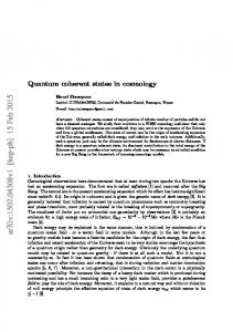
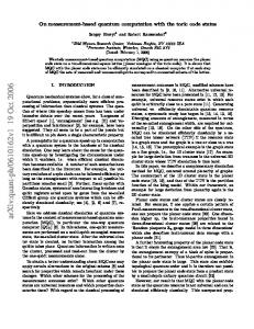
where cos2 θ (sin2 θ) is the reflectivity (transmissivity) of the beamsplitter. Now consider the overlap between the output and input states. Using the relationship [10] hτ |αi = exp[−1/2(|τ |2 + |α|2 ) + τ ∗ α] we find hγ|a hβ|b| cos θγ + i sin θβia | cos θβ + i sin θγib = exp[−(γ 2 + β 2 )(1 − cos θ) + 2i sin θγβ] (6) Now suppose that θ is sufficiently small such that θ2 α2 > 1. To evaluate just how large α needs to be we use the exact expression for the BS gate, as given in Eq.5, to calculate the output state of the CNOT. We assume ideal bit flip operations and cat state preparation. Our figure of merit is the average fidelity between the exact output and the ideal output, as given by Eq.16. The results are shown in Fig.3. In Fig.3(a) the average fidelity is plotted as a function of α. Fidelities of 0.9 and above require α > 10. Such signal sizes, although commonplace in the computational basis would be challenging to produce and control in the superposition basis and the required technology is probably some years away. On the other hand in Fig.3(b) a renormalised average fidelity is plotted. This is obtained by normalising the fidelity of getting the correct output state against the sum of the fidelities for all the possible output states in the computational subensemble. If there was no movement of states out of this subensemble one would expect the two plots to be identical. The fact that the renormalised fidelities remain high for much lower values of α shows that qubit leakage is the major reason for the decreasing fidelities at moderate levels of α in Fig.3(a). This in turn suggests that experimental demonstrations, albeit with low efficiency, may be possible for α’s as small as 3. The major sources of error in our scheme are expected to be, in order of increasing significance: (i) errors due to non orthogonal code states, (ii) errors due to failure of the two qubit gate condition (θ2 α2 3 (see Eq.3). Figure 3(a) shows that the second source of errors is small for α > 20. The third source is equivalent to a small rotation error in the code space; the fourth source causes a collapse to the one logical state, while the final source is a phase error. It can be shown [17] that good quantum error correction codes are available to correct these errors and further that error correction can be implemented in a fault tolerant fashion. In this letter we have presented a quantum computation scheme based on encoding qubits as vacuum and coherent states, and their superposition. The optical networks required are simple and compatible with current optical communication networks. As well as the long term goal of quantum computation, applications in quantum communication protocols seem likely. Although the coherent amplitudes needed for scalable computation are quite large our results indicate that experimental demonstrations with modest amplitudes should be possible.
5
REFERENCES [1] P. G. Kwiat, E. Waks, A. G. White, I. Appelbaum and P. H. Eberhard, Phys. Rev. A 60, R773 (1999). [2] W. Tittel, J. Brendel, B. Gisin, T. Herzog, H. Zbinden and N. Gisin, Phys. Rev. A 57, 3229 (1998). [3] D. Bouwmeester, J. W. Pan, K. Mattle, M. Eibl, H. Weinfurter and A. Zeilinger, Nature 390, 575 (1997). [4] E. Knill and L. Laflamme and G. J. Milburn, Nature 409, 46 (2001). [5] A. Furasawa, J. L. Sørensen, S. L. Braunstein, C. A. Fuchs, H. J. Kimble and E. S. Polzik, Science 282, 706 (1998) [6] S. Lloyd, S. L. Braunstein, Phys. Rev. Lett. 82, 1784 (1999). [7] S. D. Bartlett, Hubert de Guise, B. C. Sanders, quant-ph/0109066 (2001). [8] H. Jeong and M. S. Kim, quant-ph/0109077 (2001). [9] D. Gottesman, A. Kitaev, J. Preskill, Phys. Rev. A 64, 012310 (2001). [10] D. F. Walls and G. J. Milburn, Quantum Optics (Springer-Verlag, Berlin, 1994). [11] M. Nielsen and I. Chuang, Quantum computation and quantum information (Cambridge University Press, Cambridge, UK 2000). [12] S. Song, C. M. Caves and B. Yurke, Phys. Rev. A 41, 5261 (1990). [13] M. Dakna, T. Anhut, T. Opatrny, L. Knll and D. -G. Welsch, Phys. Rev. A 55, 3184 (1997). [14] C. Monroe, D. M. Meekhof, B. E. King and D. J. Wineland, Science 272, 1131 (1996). [15] M. Brune, E. Hagley, J. Dreyer, X. Maitre, A. Maali, C. Wunderlich, J. M. Raimond and S. Haroche, Phys. Rev. Lett. 77, 4887 (1996). [16] Q. A. Turchette, C. J. Hood, W. Lange, H. Mabuchi and H. J.Kimble, Phys. Rev. Lett. 75, 4710 (1995). [17] T. C. Ralph, G. J. Milburn and W. J. Munro, in preparation (2001). Acknowledgements. GJM acknowledges the support of the Institute for Quantum Information, California Institute of Technology where this work was initiated. WJM acknowledges funding in part by the European project EQUIP(IST-1999-11053). The Australian Research Council Special Research Centre for Quantum Computer Technology supported this work.
6
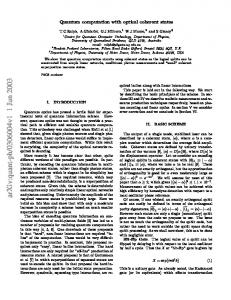
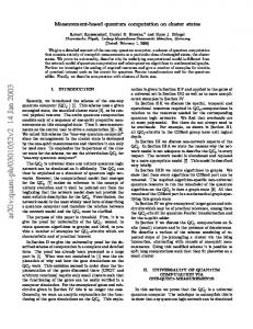
FIGURES FIG. 1. Schematic of Hadamard gate based on the two qubit beamsplitter gate (BS) and conditional implementation of the bit flip gate (F). If an even number of photons is counted then the output is in the desired state. If an odd number of photons is counted a bit flip operation is needed to place the output in the correct state. FIG. 2. Schematic of CNOT gate based on two qubit beamsplitter gates (BS) and conditional implementation of bit flip gates (F). FIG. 3. Performance of the CNOT gate as a function of the magnitude of α. In (a) the average fidelity is plotted against α. The high fidelities at very low values of α are an artefact of the non-orthogonality of small α states. In (b) the fidelities are renormalised against the total fidelity for a result within the computational subensemble of states.
7
plus cat=no flip minus cat=bit flip
|unkown> BS |plus cat>
Ralph_fig1
F
|output>
|control>
|control out> plus cat=no flip minus cat=bit flip
|target>
BS plus cat=no flip minus cat=bit flip
BS |plus cat>
F BS |plus cat>
Ralph_fig2
|target out> F
(a)
1 0.8
average Fidelity
0.6 0.4 0.2 10
20
30
40
50
coherent amplitude (α)
coherent amplitude (α) (b) 2 0.8
renormalized average 0.6 Fidelity 0.4 0.2
Ralph_fig3
4
6
8
10