tion 2.4 presents the tools used for QCA design and simulation, and a survey of .... of these four distinct classes of QCA and their advantages and disadvantages ..... The basic elements of sequential circuits including latches and counters have.
2 Quantum-dot Cellular Automata Weiqiang Liu, Máire O’Neill, and Earl E. Swartzlander, Jr.
As a replacement for CMOS technology, quantum cellular automata was proposed by Lent et al. [1] to implement classic cellular automata with quantum dots. In order to distinguish this proposal from models of cellular automata performing quantum computation, the term has been changed to quantum-dot cellular automata (QCA). QCA is a revolutionary technology that exploits the inevitable nanolevel issues to perform computing. It has potential advantages including high speed, high device density, and low-power dissipation. Research on QCA has received considerable interest since its invention. A number of leading research groups around the world are working at both the physical and logic levels. The research group at the University of Notre Dame [2] has been leading QCA research for two decades. Most of these groups were only involved in research at the physical level before the release of the state-ofart design and simulation tool QCADesigner in 2004 [3]. Since then, QCA research at the logic level has expanded dramatically. A survey of the simulation and experimental research on the fabrication of QCA devices has been provided by Macucci [4], and an aggregation of previous work on the design and test of digital circuits in QCA has been presented by Lombardi and Huang [5]. This chapter provides background information on QCA technology and surveys previous research into QCA circuit design. This chapter is organized as follows. Section 2.1 outlines QCA fundamentals including the general QCA model, basic gates, wires, and crossover options. Possible physical implementations of QCA circuits are overviewed in Section 2.2. The clocking schemes in QCA are introduced in Section 2.3. Section 2.4 presents the tools used for QCA design and simulation, and a survey of 11
12
Design of Semiconductor QCA Systems
general digital design in QCA is presented in Section 2.5. A preliminary set of design rules for QCA is discussed in Section 2.6, and a summary of the chapter is provided in Section 2.7.
2.1
QCA Fundamentals
2.1.1 QCA Cells and Wires
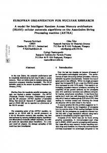
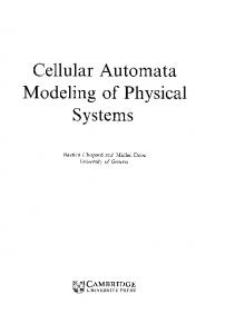
A general QCA cell is a square nanostructure with four quantum dots as shown schematically in Figure 2.1(a). Dots are the places where a charge can sit. The cell is populated with two electrons that can tunnel between the four quantum dots. Tunneling action only occurs within the cell and no tunneling happens between cells. The numbering of the dots (denoted as i ) in the cell goes clockwise starting from the dot on the top right: top right dot i =1, bottom right dot i =2, bottom left dot i =3 and top left dot i =4. A polarization P in a cell is defined as P=
( ρ1 + ρ3 ) − ( ρ2 + ρ4 ) ( ρ1 + ρ2 + ρ3 + ρ4 )
(2.1)
where ρi denotes the electronic charge at dot i. The polarization measures the charge configuration—that is, the extent to which the electronic charge is distributed among the four dots. Binary information is represented in QCA by
Quantum dot
Electron “0” Polariztion –1
“1” Polariztion +1 (a)
(b) Figure 2.1 Schematics of QCA cell and wire: (a) binary QCA cells, (b) a QCA wire composed of coupled cells.
Quantum-dot Cellular Automata
13
using the position of two mobile electrons in each logic cell. When the barriers between dots are low enough to free the electrons under the control of the clocking scheme, these two electrons tend to occupy antipodal sites within the cell due to Coulombic repulsion [1] as shown in Figure 2.1(a). The two charge configurations can be used to represent binary “0” and “1” with a polarization of –1 and +1, respectively. The combination of quantum confinement, Coulombic repulsion, and the discrete electronic charge produces bistable behavior. If a cell is placed near a driver cell whose polarization is fixed, the cell will align its polarization with that of the driver cell. It has been illustrated that the cell-to-cell interaction is highly nonlinear, (i.e., even a slightly polarized input cell induces an almost fully polarized output cell) [6]. Therefore, information can be transferred by interaction between neighboring cells along a line of QCA cells. The polarization of the input can be transferred by the intercell Coulombic repulsion along the one-dimensional cell array. A QCA “wire” is a chain of cells as shown in Figure 2.1(b), where the cells are adjacent to each other rather than a physical wire. Such a wire is used as an interconnection between all kinds of logic components. Therefore, QCA has the ability to offer “processing-in-wire” [7]. Since no electrons tunnel between cells, QCA provides a mechanism for transferring information without current flow. 2.1.2 QCA Basic Gates
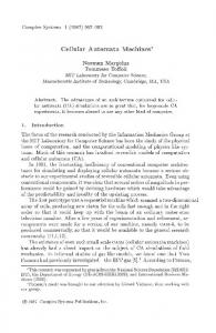
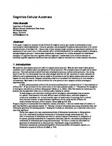
Based on the mutual interaction between cells, basic logic components including an inverter and a three-input majority gate can be built in QCA. Examples of these two gates are shown in Figure 2.2. An inverter is made by positioning cells diagonally from one another to achieve the inversion functionality. A majority gate consists of five QCA cells that realize the following function: M (a ,b , c ) = ab + bc + ac
(2.2)
Majority gates can be easily converted to AND or OR gates by using a fixed value for one of the inputs. For example, a two-input AND gate is realized by fixing one of the majority gate inputs to “0”: AND (a ,b ) = M (a ,b ,0) = ab
(2.3)
Similarly, an OR gate is realized by fixing one input to “1”: OR (a ,b ) = M (a ,b ,1) = a + b
(2.4)
14
Design of Semiconductor QCA Systems
Input
Output
(a) a
b
Output
c (b) Figure 2.2 QCA basic gates: (a) inverter, (b) majority gate.
In combination with inverters, these two logic components can be used to implement any logic function. 2.1.3 QCA Wire Crossings
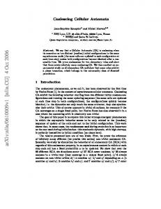
One of QCA’s unique characteristics is the capability to create different signal wire crossings. In QCA technology, two crossover options are available: coplanar crossings and multilayer crossovers. A coplanar crossing [6] was proposed as a unique property of a QCA layout and implements crossovers by using only one layer, as shown in Figure 2.3(a), which demonstrates different forms of coplanar crossings. Half-cell displacement inverters comprised of only two regular cells, as shown in Figure 2.3(a), are used in order to propagate signals correctly. This will result in using a large number of this type of inverter in coplanar designs. A coplanar crossing uses both regular and rotated cells. The two types of cells do not interact with each other when they are properly aligned. Previous research suggests that coplanar crossings may be quite sensitive to misalignment [8] and vulnerable to noise [9, 10]. The other alternative is a multilayer crossing [11], which uses more than one layer of cells similar to the routing of metal wires in CMOS technology, as shown in Figure 2.3(b). Multilayer crossovers are expected to achieve more
Quantum-dot Cellular Automata
15
(a)
(b) Figure 2.3 Two crossover options in QCA: (a) coplanar crossover, (b) multilayer crossover.
reliable results in simulations [12]. However, multilayer crossovers are not easy to fabricate due to the multiple layer structure, and the cost to fabricate a multilayer crossover is expected to be significantly greater than that of a coplanar crossing. The cost difference between the coplanar and multilayer crossovers affects the overall cost of a design to some extent.
2.2
Physical Implementations of QCA
To date, a number of different implementations to realize the bistable and local interaction required by the QCA paradigm have been proposed. Both electrostatic interaction-based QCA implementations (metal-dot, semiconductor, and molecular) and magnetic QCAs have been investigated. A brief overview
16
Design of Semiconductor QCA Systems
of these four distinct classes of QCA and their advantages and disadvantages follows. 2.2.1 Metal-Island QCA
The metal-island QCA cell was implemented with relatively large metal islands (about 1 micrometer in dimension) to demonstrate the concept of QCA [13, 16]. The dots are made of aluminum with aluminum oxide tunnel junctions between them. In this metal-island QCA cell, electrons can tunnel between dots via the tunnel junctions. These two pairs of dots are coupled to each other by capacitors. Two mobile electrons in the cell tend to occupy antipodal dots due to electrostatic repulsion. Metal-island QCA components including majority gates, binary wires, memories and clocked multistage shift registers have been fabricated [16–19]. The operating temperature for metal-island QCA is extremely low, in the range of milli-Kelvin, to achieve the appropriate electron filling. This prevents the construction of complex QCA circuits running at room temperature. Therefore, the metal-island implementation is not currently seen to be a practical approach for future QCA systems. 2.2.2 Semiconductor QCA
A semiconductor QCA cell is composed of four quantum dots manufactured from standard semiconductive materials [20–22]. A device was fabricated in [23] using a GaAs/AlGaAs heterostructure with a high-mobility two-dimensional electron gas below the surface. Four dots are defined by means of metallic surface gates. The cell consists of two double Quantum-Dot systems (half cells). Half cells are capacitively coupled. The charge position is used to represent binary information and the Quantum-Dot interactions are dependent on electrostatic coupling [24]. A semiconductor implementation promises the possibility of fabricating QCA devices with the advanced fabrication processes used for existing CMOS technology. However, current semiconductor processes cannot provide mass production with the ultrasmall feature sizes required by QCA technology. To date, most QCA device prototypes have been demonstrated with semiconductor implementations. Hence, the research presented in this book is conducted based on semiconductor QCA. However, the conclusions drawn from the research based on semiconductor implementation are applicable to other implementation types. 2.2.3 Molecular QCA
A molecular QCA cell [25–28] is built out of a single molecule, in which charge is localized on specific sites and can tunnel between those sites. In the molecule shown in [29], the free electrons are induced to switch between four ferrocene
Quantum-dot Cellular Automata
17
groups that act as quantum dots due to electrostatic interactions, and a cobalt group in the center of the square provides a bridging ligand that acts as a tunneling path. The molecules are expected to be as small as 1 nm or even smaller, which promises room-temperature operation, ultrahigh density and high speed in the terahertz range. Room-temperature operation of a molecular QCA cell has been experimentally confirmed [30]. The difficulty in realizing molecular QCA is due to the high-resolution synthesis methods and positioning of molecule devices. New construction methods for molecular QCA, including selfassembly on DNA rafts, are under investigation [31]. However, it is still very difficult to fabricate molecular QCA systems with current technologies. 2.2.4 Magnetic QCA
A magnetic QCA cell is an elongated nanomagnet with a length of around 100 nm and a thickness of 10 nm [32–34]. The shape of the nanomagnet varies for different schemes. The binary information in magnetic QCA cells is based on their single domain magnetic dipole moments. The usage of magnetic interaction inherently minimizes the energy. Although its operating frequency is rather low (around 100 MHz), it has the advantage of room-temperature operation, extremely low power dissipation and high thermal robustness. A three-input majority gate in magnetic QCA has been fabricated [34]. The first large-scale QCA systems appear to be possible with a magnetic QCA circuit, which has fewer challenges during the manufacturing process compared with other implementations [33].
2.3
Clocking Schemes
Functional QCA circuits need to be clocked in order to operate correctly. The transitions of QCA states occur under the control of potential barriers between the quantum dots in QCA cells, and it is the QCA clock that lowers and raises the tunneling barriers. Clocking in QCA not only controls data flow but also serves as the power supply [35]. 2.3.1 Typical Four-Phase Clocking
Quasi-adiabatic four-phase clocking is typically used in QCA circuits offering deep pipelines. Quasi-adiabatic switching ensures the system is always in its instantaneous ground state, which significantly reduces metastability issues [36]. In quasi-adiabatic switching, QCA cells are timed in four successive clocking zones. A calculation is performed in one clocking zone. Its state is then frozen and used as the input to a successor zone. During the calculation, the successor
18
Design of Semiconductor QCA Systems
zone is kept in an unpolarized state so that it has no influence on the predecessor zone. The four clocking phases exist in each QCA clocking zone and there is a 90° phase shift from one clocking zone to the next, which is shown in Figure 2.4(a). The clock signals of QCA circuits are generated by applying an electric field to the QCA cells to modulate the tunneling barrier between dots (i.e., the interdot barrier). The electric field can be generated by CMOS circuits or carbon nanotubes [37]. The cells are in the HOLD phase when the interdot barrier is high and in the RELAX phase when the interdot barrier is low. When the inter-dot barrier changes from low to high or high to low, the cell is in the SWITCH or the RELEASE phase, respectively. The transition of information occurs during the SWITCH phase. A cell is latched while it is in the HOLD phase. Since the cells in one clocking zone become latched and remain in this state until the cells are latched in the next clocking zone, a clocked QCA “wire” can be treated as a chain of D-latches. The smallest unit of delay in QCA is a clocking zone delay (D−1), which is a quarter of a clock cycle delay(Z−1). As shown in Figure 2.4(b), the following relationship holds:
(a)
(b)
Figure 2.4 Typical QCA clocking scheme: (a) clock signals in four clocking zones, and (b) a clocked QCA wire.
Quantum-dot Cellular Automata
Z −1 = D −4
19
(2.5)
Although conventional logic functions can be easily mapped to majority logic, the unique clocking scheme in QCA makes it difficult to translate a CMOS architecture directly into its QCA counterpart. Although other clocking schemes have been proposed for magnetic QCA [38], in this book fourphase clocking is assumed. 2.3.2 Clocking Floorplans
Two types of clocking floorplans [39] can be used in QCA circuit implementations, namely columnar regions [Figure 2.5(a)] and zone regions [Figure 2.5(b)]. The columnar approach is assumed to be more practical in physical implementation. However, it has difficulty in realizing short feedback loops and high circuit densities. On the other hand, the zone approach can achieve these aspects. Smaller clocking zones also increase the robustness of a QCA circuit in terms of thermal effects [40]. The size of a zone is a trade-off between imple-
(a)
(b)
Figure 2.5 QCA clocking floorplans: (a) columnar region, and (b) zone region.
20
Design of Semiconductor QCA Systems
mentation difficulty and circuit efficiency. Smaller zones are more difficult to implement but can be more area-efficient. The floorplan of the QCA timing zones has a significant impact on the actual layout of a QCA circuit. This is sometimes referred to as the “layout = timing” problem [41]. In this book, the main focus is on the functionality of circuits. Therefore, the clocking floorplans of the proposed QCA architectures are designed using small zones. 2.3.3 Clocking for Reversible Computing
An alternative clocking scheme, namely Bennett clocking, was proposed as a practical means to perform reversible computing with lower power dissipation in QCA circuits [42]. The principle of Bennett clocking is to keep copies of the bit information by echoing inputs to outputs [43]. An example of Bennett clocking waveforms is shown in Figure 2.6. The timing of the Bennett clock is altered in order to keep the bit information in place until a computational block is finished. Then the information is erased during the reverse order of computation. To implement Bennett clocking in QCA, only the timing of the clocking is required to be altered without changing the circuit itself. Bennett clocking can reduce the power dissipation to even less than kBT ln(2) [42]. However, this is achieved at the cost of speed. A general floorplan was also proposed for reversible QCA circuits [44].
2.4
Design and Simulation Tools
Several design and simulation tools for QCA circuits have been developed by using approximations with low computational complexity, which can be used for relatively large scale circuit layout and simulation. These tools include MA-
Figure 2.6 Bennentt clocking waveforms.
Quantum-dot Cellular Automata
21
QUINAS [45, 46], QBART [47] and QCADesigner [3]. A SPICE macro model for QCA has also been proposed and experimentally verified [48], in addition to the hardware description language (HDL)–based design tool HDLQ, for verifying the logic behavior of QCA circuits [49]. More recently, a number of add-on features for the QCADesigner tool have been developed. These include an automatic layout generator for combinational circuits in QCADesigner [50] and a simulator for power dissipation and error estimation known as QCAPro [51]. Of these simulation tools, QCADesigner is the state-of-the-art and the most widely used QCA simulation tool. QCAPro is the first simulator for estimating both the polarization error and power dissipation in QCA circuits. These two design tools are introduced here. 2.4.1 QCADesigner
QCADesigner [3] is the most popular simulation tool for semiconductor QCA circuit design. It allows users to quickly layout a QCA design and determine its functionality in a reasonable time frame. QCADesigner supports both coplanar and multilayer crossings. The design flow of QCADesigner is shown in Figure 2.7. In the current version, QCADesigner ver 2.0.3 [52], there are two simulation engines: the bistable engine and the coherence vector engine. 2.4.1.1 Bistable Simulation Engine
The Bistable engine is implemented with each cell modeled as a simple twostate system. The following Hamiltonian matrix can be used to describe the two-state system: ⎡ 1 k ⎢ − 2 Pj E i , j Hi = ⎢ ⎢ −γ ⎢⎣
⎤ ⎥ ⎥ 1 Pj E ik, j ⎥ ⎥⎦ 2 −γ
(2.6)
where, Pj is the polarization of cell j. E k is the kink energy between cell I and j. This kink energy is associated with the energy cost of two cells having opposite polarization γ is the tunneling energy of electrons within the cell, which is controlled by the clock. The engine uses the intercellular Hartree approximation (ICHA) [1] [6] [53] to solve a quantum mechanical system by treating each individual cell quantum-mechanically and coupling neighboring cells based on the Coulombic interaction between cells. ICHA is a very important method to determine the stable state of multicell QCA systems, as it is the foundation of almost all QCA work that has been done so far [54].
22
Design of Semiconductor QCA Systems
Figure 2.7 The design flow of QCADesigner.
In the ICHA method, the sum of the Hamiltonian is over all cells within an effective radius of cell i. Only the effects of cells that fall into a circle defined by the radius-of-effect, R (in nanometers), are considered for each cell. R is an important parameter that can be set before simulation. It is assumed that the circuits remain very close to the ground state during switching which is quasiadiabatic. Therefore, the stationary state of each cell can be calculated by solving the time-independent Schrödinger equation [3] as follows: H i Ψi = E i Ψi
(2.7)
Quantum-dot Cellular Automata
23
where, Hi is the Hamiltonian described by (2.6). ψi is the state vector of the cell, and Ei is the energy associated with the state. To verify the logical functionality of a design, this eigenvalue problem reduces to performing the following calculation: E ik, j ∑ j Pj 2γ Pi = (2.8) ⎛ E ik, j ⎞ 1+ ⎜ P ∑ j j⎟ ⎝ 2γ ⎠ The bistable engine iteratively computes the polarization of each cell in the circuit until the whole circuit converges to within a preset tolerance. Full quantum mechanical calculation including quantum correlation effects within and between cells is computationally intractable for large QCA systems due to the exponential growth of the size of the Hamiltonian. By using the ICHA method, the computation only increases linearly with the number of QCA cells. Therefore, the bistable engine using ICHA is able to simulate large QCA circuits in a very efficient manner. Recent work [54] has shown that the ICHA method is generally valid and sufficient for verifying the functionality of a QCA circuit. However, the price of the quick computation is inaccuracy of the QCA dynamics due to ignoring the intercellular entanglement [55], which sometimes causes incorrect logical outputs of the QCA circuits. In order to overcome the shortcomings of the ICHA method, modifications to the circuits are usually required to make the designs robust. It should be noted that these modifications may not be necessary in practice. It is important to emphasize that the designs in this book are good starting points, but they will need refinement before actual circuits are fabricated. 2.4.1.2 Coherence Vector Simulation Engine
The coherence vector engine is a more accurate engine that provides dynamic simulation. It is based on the density matrix approach and is commonly used in simulation of QCA dynamics. The cells in the engine are modeled similarly to those in the bistable engine. However, it includes the power dissipative effects and performs a time-dependent simulation. In the density matrix approach, the coherence vector λ is a vector representation of the density matrix of a cell. The motion for the coherence vector including dissipative effects can be described as follows [35]: ∂λ 1 = Γ × λ − λ − λss ∂t τ
(
)
(2.9)
24
Design of Semiconductor QCA Systems
where, Γ an energy vector representing the energy environment of the cell, ⎤ 1⎡ Γ = ⎢ −2 γ,0, ∑ E ik, j Pj ⎥ ⎢⎣ ⎥⎦ j ∈S
(2.10)
is the relaxation time that is implementation dependent and λss is the steady state coherence vector, ⎛ Γ ⎞ Γ ⎟ λss = − tanh ⎜ (2.11) ⎜⎝ 2kBT ⎟⎠ Γ where, ប is the reduced Planck constant, T is the temperature in Kelvin and kB is the Boltzmann’s constant. The coherence vector for each cell is calculated by Equation (2.9) using an explicit time marching algorithm. For each time step the Γ and λss for each cell is evaluated and then the coherence vector for each cell is stepped forward in time. For more details on the dynamics of QCA systems using the coherence vector formalism, refer to [35, 56]. It is computational expensive to determine the steadily state density matrix [55]. Meanwhile, simulation using either a bistable engine or a coherence vector engine provides the same result for semiconductor QCA circuits in most cases. Therefore, a bistable engine is usually used in the simulation of QCA circuits. 2.4.1.3 Simulation Parameters
In the current QCADesigner version 2.0.3, the size of the basic quantum cell was set at 18 nm by 18 nm with 5 nm diameter quantum dots. The center-tocenter distance is set at 20 nm for adjacent cells. Research with silicon atom dangling bonds [30] shows the potential to operate at room temperature with cell sizes on the order of 2 nm × 2 nm, which will reduce the area by two orders of magnitude. The larger size was used in this research to maintain consistency with other recent QCA designs. There are several parameters that can be set by designers in the bistable engine. The total simulation is divided by the number of samples. For each sample, the simulation engine looks at each cell and calculates its polarization based on the polarizations of its effective neighbors that are determined by the radius of effect. The number should not be chosen too small as there will be insufficient samples to get the correct results. However, a larger number results in a longer simulation time. If the simulation results should be something other than that they are, a larger number should be used [52]. The radius of effect determines how far each cell will look to find its neighbors’. The least radius of effect should include the next-to-nearest neighboring cells. For multilayer
Quantum-dot Cellular Automata
25
crossings, the radius of effect should be greater than that of the layer separation. In this book, the default value (i.e., 65 nm) is used. Based on the above reasons, different numbers of samples are selected for each simulation in the following chapters. All the other parameters that are the defaults for the bistable approximation are listed as follows: • Convergence tolerance = 0.001; • Radius of effect = 65 nm; • Relative permittivity = 12.90; • Clock high = 9.80e −22J; • Clock low = 3.80e −23J; • Clock amplitude factor = 2.00; • Layer separation = 11.50 nm; • Maximum iterations per sample =100. 2.4.2 QCAPro
QCAPro is a probabilistic modeling tool that can be utilized to estimate the polarization error and power dissipation under abrupt switching in QCA circuits. It is a graphic user interface (GUI)-based tool built on the Bayesian network [57, 58]. The tool can estimate erroneous cells in large QCA circuit designs by fast approximation. It also estimates switching power loss in QCA circuits using the upper bound power model [59]. Several parameters can be used to analyze and optimize QCA designs. Users can set values for temperature and tunneling energy. QCAPro estimates the upper bound of power dissipation as a function of cell polarization, clock energy, and quantum relaxation time. The input required for the current version, QCAPro 1.0 [51], is the layout file generated by QCADesigner. It can provide the average, maximum, and minimum power consumption of a QCA circuit during input switching. The design flow of QCAPro is shown in Figure 2.8.
2.5
Research Into QCA Digital Design
Although the implementation of QCA technology is still at an early stage, researching high-level logic design is as important as physical design and can help guide its development. QCA technology not only provides a fundamentally novel physical structure, but also offers a new kind of computing architecture for digital design. The special “processing-in-wire” and “memory-in-motion”
26
Design of Semiconductor QCA Systems
Behavioral Description
Figure 2.8 The design flow of the QCAPro tool. (From [51]. © 2011 IEEE.)
features [7] require the development of novel circuit architectures and new design methods that are different from traditional CMOS technology. The unique characteristics of QCA technology also present new challenges for design and testing. 2.5.1 Computer Arithmetic Circuits
Among the circuits designed in QCA, adders and multipliers have received considerable interest due to their importance in computing systems [60–62]. The first QCA circuit proposed was a 1-bit full adder [6] using five majority gates. The design was further optimized by Wang et al. [63], to use only three majority gates and three crossovers, thus significantly reducing the complexity of the adder. Wang’s adder was later revised for multilayer implementation [64]. The Hänninen adder [65, 66] uses the same addition algorithm as Wang’s adder, but with an optimized layout. The clocking zones were rearranged to achieve a more robust design. A CFA was proposed by Cho and Swartzlander [67], and is a layout optimized multilayer full adder. This QCA CFA consumes only one clocking zone delay per bit, which significantly reduces the overall delay in large adders. Cho and Swartzlander also designed and analyzed a CLA [68] and
Quantum-dot Cellular Automata
27
CSAs [69, 70]. More recently, a family of prefix adders (which are variations of CLAs) including Kogge-Stone, Brent-Kung, Ladner-Fisher and Han-Carlson adders, were designed in QCA by reducing the carry computation to a prefix computation [71, 72]. By using a new majority logic reduction technique, the prefix adders achieve the best performance to date in terms of delay, especially for large adders. Binary multiplier designs based on the direct paper-and-pencil algorithm have also been extensively studied in QCA. The first QCA multiplier proposed was a bit-serial multiplier with one operand in bit-serial format and the other in parallel format [60]. The design was further optimized to perform more robustly by Hänninen and Takala [73]. Cho and Swartzlander designed a serial parallel multiplier based on filter networks using a bit-serial systolic array structure [74] [67]. Fast multipliers have also been proposed by using Wallace and Dadda approaches to reduce the propagation delays [75]. Array multipliers were studied in QCA in which both operands arrive in parallel [76, 77]. A radix-4 recoded multiplier was also designed using modified Booth recoding and carry-save addition to achieve stall-free pipeline operation [78]. Other research into QCA computer arithmetic circuits has included the design of an iterative Goldschmidt divider [79] and a restoring divider [80]. A novel QCA matrix multiplier was recently proposed [81] based on majority gates, data flow using quasi-adiabatic switching, an OR loop memory, and a tristate buffer. Systolic matrix multipliers of varying size and dimension have been designed and analysed [82, 83]. Galois Field multipliers [84, 83] and Montgomery multipliers [85, 86] for cryptographic algorithms have also been designed. Decimal arithmetic for specific applications has also been studied in QCA [87–90]. 2.5.2 Combinational Circuits
Combinational circuits based on majority gates and inverters have been considered in QCA. A universal gate, the and-or-inverter (AOI) gate [91], was proposed to efficiently implement elementary gates. Two-level logic functions can be easily implemented by a single AOI gate. Various multiplexer architectures [92–94] have been designed for more complex circuits. A 4-bit barrel shifter comprising a shifting unit, decoder and serial OR array was designed by Vetteth et al. [95] and Huang et al. [96] designed a decoder and parity checker using a modular tile-based method. 2.5.3 Latches and Sequential Circuits
The basic elements of sequential circuits including latches and counters have been investigated. R-S latch [97, 98], D latch [98–101] and J-K latch [102, 103] designs in QCA have been studied. Logically reversible latches were de-
28
Design of Semiconductor QCA Systems
signed based on the basic reversible Toffoli and Fredkin gates [104]. However, how to design the latches in QCA is still an open issue. A state machine design in QCA is also a challenge. As a starting point, counter designs have been proposed such as a Gray code counter [98], a ring counter [99], and a synchronous counter [103]. A traffic light controller and an ISCAS89 S27 benchmark were also designed in QCA using a stretching algorithm for delay matching [98]. A data tag method was proposed [79] as an alternative way to control the various elements of the machine. 2.5.4 Memory Design
Unlike CMOS technology, there is no QCA equivalent of a capacitor to keep the state. The states must be kept in a ring of QCA cell arrays through a loop of clocking zones, which is sometimes referred to as “memory-in-motion” [7]. QCA memory structures can be categorized as two types: loop-based and linebased memory. The loop-based memory cell [7, 105–108] stores data with a closed QCA wire loop which is partitioned into four clocking zones. As a result, a large number of clocking zone delays are introduced. In a line-based memory cell [109–111], information is stored through a QCA line with a revised clocking scheme to achieve higher memory density. 2.5.5 General and Specific Processors
A microprocessor named “Simple 12” was designed in QCA [41, 47, 112]. The design was further improved to achieve robust operation in the presence of sneak noise paths [9]. A 4-bit processor design based on an accumulator architecture shows that QCA technology could potentially be applied in future computers [8, 12, 113]. Programmable logic has also been studied to implement universal logic in QCA [114–117]. Special purpose processors have also been investigated to perform signal processing tasks. For example, nonlinear filters based on QCA arrays were proposed for signal processing algorithms [118], and filters and an array processor were proposed for image processing in QCA [119, 120]. Cryptographic processors for block ciphers and stream ciphers have also been designed [121, 122]. 2.5.6 Design Methods and Design Automation
General design methods to achieve large-scale modular and efficient QCA circuits are important. A specific arrangement of clocking—namely, trapezoidal clocking—was proposed to reduce the design area [41]. This was also considered to be a possible method to implement feedback paths. Tile-based modular design was studied to implement versatile logic [96] and based on the conventional concept of a flip-flop, and a stretching algorithm was proposed [98] for
Quantum-dot Cellular Automata
29
assigning clocking zones to QCA sequential circuits by matching delays. The delay-matching design method ensures that all paths from the outputs to the inputs of flip-flops have the same delays. However, many unnecessary delays are introduced due to the strict matching strategy resulting in an expansion of the overall number of cells and circuit size. Two-dimension clocking was proposed [97] to reduce the longest line length in each clocking zone. A globally asynchronous, locally synchronous (GALS) method was also proposed to reduce the “layout=timing” dependency [123–125]. A cut-set retiming procedure as described in Chapter 6, was proposed to resolve the timing issues in QCA [85, 86] and general systematic approaches for the design of systolic array architectures, as outlined in Chapter 7, have been studied [82, 83]. Research into design automation, including logic synthesis, placing, routing and layout, is required to deal with the design challenges in QCA systems. As majority gates are the logic primitive in QCA, logic synthesis based on majority logic has been extensively studied [126–129]. A tool referred to as the majority logic synthesizer (MALS) was developed for general multilevel majority/minority network synthesis [130, 131]. An algorithm targeting logic-level abstraction for area minimization was also proposed for QCA circuits [132] and automatic partitioning and placement for the generation of QCA layouts have been investigated [133, 134]. 2.5.7 Testing, Defects and Faults
The testing of defects and faults is critical in nanoscale integration such as QCA circuits. Although it is difficult to address the testing of QCA devices at this early stage, this aspect has been investigated by theoretical analysis and simulation. Fault models and prototype tools have been developed [135, 136]. Unique testing features and the defect characteristics have also been identified and studied [137–139]. The scaling of QCA basic gates in the presence of defects from process variations has been evaluated [140] and defect tolerance properties in tile-based QCA design studied [141]. The reliability dependence on the failure rates of macro components for arithmetic circuits has been investigated [142, 143]. Other research in this area has included the study of defect characterization and tolerance in sequential circuits [144, 145], an analysis of the displacement tolerance of QCA interconnects [146] and a discussion on the defects and faults in QCA programmable logic [147]. An information-theoretic method was also proposed to analyze the defect tolerance of QCA circuits [148]. The testing and fault tolerance of reversible QCA circuits has also been investigated [149–151].
30
2.6
Design of Semiconductor QCA Systems
Basic Design Rules1
When mapping a digital design to majority logic-based QCA circuits, knowledge of the layout and timing constraints is necessary. The objective of defining design rules is to simplify mapping from a circuit schematic to an actual layout implementation. Design rules have played an important role in the development of CMOS technology. A CMOS design rule set specifies certain geometric and connectivity restrictions to ensure sufficient margins that take into account variability in the semiconductor manufacturing processes to ensure that circuits function correctly. Limited research has been conducted into defining design rules for QCA circuits [152, 153] and guidelines for achieving robust QCA designs [10]. Developing design rules for QCA technology will help designers understand QCA features and how to efficiently achieve correct functionality and reliability in QCA circuits. This will ultimately help to promote the development of practical QCA systems. Due to the unique clocking scheme used in QCA, there is a critical relationship between the layout and timing, referred to as “layout=timing” [41]. Consequently, the timing rules are as important as the layout in QCA. The careful placement of the cells to satisfy both types of rules can produce a more reliable design. Based on the research conducted into QCA circuit designs, a set of basic QCA design rules has been compiled [84]. Both the layout and timing rules are discussed in this section. Note that most rules are based on QCADesinger using the ICHA. 2.6.1 Layout Rules
A design rule set specifies certain geometric and connectivity restrictions to ensure that circuit components operate correctly. Following this concept, some layout design rules for QCA are described with regard to the following: 1. The maximum number of cells in a clocking zone; 2. The minimum number of cells in a clocking zone; 3. The minimum wire spacing for signal separation. 2.6.1.1 The Maximum Number of Cells in a Clocking Zone
QCA computation is achieved by relaxing the physical array to its ground state. Computing with the ground state has the undesired accompanying effect of being temperature sensitive. Thermal fluctuations may excite the QCA array above its ground state, which may produce an incorrect output. A complete analysis of thermodynamic effects has been conducted by Lent et al. [40]. As more cells are placed in a single clocking zone, more errors may occur. The 1. Section 2.6 is based on [84].
Quantum-dot Cellular Automata
31
limitation on the number of QCA cells to avoid undesired kink effects is given by [40]: N ≤e
Ek kBT
(2.12)
where, N is the number of cells in the array, Ek is the kink energy between two cells, kB the Boltzmann constant, and T is the operating temperature. The maximum operating temperature is affected by the QCA cell size. The different forms of QCA (semiconductor, magnetic, and molecular) have different kink energies, which will result in different wire length constraints [154]. Long QCA wires also result in an increased delay in signal propagation and switching, which can significantly reduce the overall operating speed. Therefore, the clock rate can be improved if a small number of cells are set into a single clocking zone. Long QCA wires should be partitioned into different clocking zones to ensure correct functionality. 2.6.1.2 The Minimum Number of Cells in a Clocking Zone
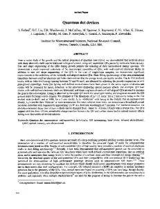
A clocking zone can contain only a single QCA cell. However, the waveform of a one-cell clocking zone can become distorted, and cascading of this kind of clocking zone could lead to incorrect results [9]. In the simulation of a wire in QCADesigner (in a range of radius of effect from 21 to 80 nm) as shown in Figure 2.9, the signals in clocking zone 1 are distorted and become worse in clocking zone 2 and finally lead to a wrong output in clocking zone 3. To achieve a reliable result, it is suggested that in most cases there should be at least two cells in each clocking zone. For a long QCA wire, the cells should be put into different clocking zones and divided evenly to avoid the effects of a one-cell clocking zone and to ensure robust signal transmission.
Figure 2.9 Distorted waveforms from one-cell clocking zones. (© 2011 IEEE. From [84].)
32
Design of Semiconductor QCA Systems
2.6.1.3 The Minimum Wire Spacing for Signal Separation
QCA cells interact through a quadrupole-quadrupole interaction, which decays inversely by a power of five of the distance between cells. Referring to Figure 2.10(a), the relationship between the cell position and the kink energy is as follows [152]: E k (r , θ ) ∝ r −5 cos ( 4 θ )
(2.13)
where, r is the distance between two cell centers. If two QCA cells are aligned properly with a center-to-center distance of one cell size as shown in Figure 2.10(b), the kink energy between them is proportional to r1–5 For two cells with a center-to-center distance of two cells, the kink energy is proportional to 1 r1−5 which is 32 times smaller. Therefore, 32 the kink energy will decay rapidly with distance, and the effective neighborhood of interacting cells can be reduced. In the QCADesigner tool, the effective neighborhood of interacting cells is determined by the radius of effect. When the next-to-nearest neighbors are included in this radius, a space of one QCA
(a)
(b) Figure 2.10 Relationship between QCA cell position and kink energy: (a) general interaction between two cells, (b) two cells with a center-to-center distance of one cell. (© 2011 IEEE. From [84].)
Quantum-dot Cellular Automata
33
cell size is sufficient separation between two wires carrying different signals. However, for a larger radius of effect, more space is required between QCA signal wires. 2.6.2 Timing Rules
A successful QCA layout is largely determined by an appropriate clocking zone assignment due to the unique “layout = timing” aspect of QCA. Therefore, when considering QCA design rules, the timing rules are as important as the layout rules and include the following: 1. The logic component timing rule; 2. Majority logic reduction to mitigate timing constraints; 3. The clocking zone assignment rule. 2.6.2.1 Logic Component Timing Rule
The timing constraint on a QCA majority gate is that all three inputs are expected to reach the device cell (central cell) at the same time in order to have fair voting. If all three input wires are equally long, the device cell can be within the same clocking zone as the inputs. However, in practice, the length of input wires is usually different. Therefore, these three inputs should be designed within the same clocking zone i, and the majority gate as well as its output should be in the successive clocking zone [(i + 1) mod 4]. As a result, at least one clocking zone delay (denoted as D −1) is required in a majority gate. A robust majority gate design is shown in Figure 2.11. Thereupon, the minimum delay in its derivatives, (that is the OR and AND gate) is also one clocking zone delay (D −1). However, the QCA inverter has only one input that does not need to be synchronized. Therefore, the QCA inverter does not require extra clocking zone
a Clocking Zone [(i+1) mod 4]
Clocking Zone i
output
b
c
Figure 2.11 A robust QCA majority gate design. (© 2011 IEEE. From [86].)
34
Design of Semiconductor QCA Systems
delays. It has been found this timing rule comes from the simulations using the ICHA method [155]. However, this timing rule should be followed to make a robust design in QCADesigner. 2.6.2.2 Majority Logic Reduction
The logic primitive used in QCA is the majority gate. Although conventional AND and OR gates can be derived from the majority gate, it is costly in terms of cell-count to design QCA circuits by directly mapping from the equivalent CMOS design. Majority logic based reduction methods [126, 129] can significantly mitigate the timing constraints of QCA circuits and reduce the circuit complexity. A QCA design should be optimized using majority logic reduction before translating it into the layout. 2.6.2.3 Clocking Zone Assignment Rule
In QCA circuits, even combinational logic, as defined in CMOS, should be synchronized. It is easy to assign clocking zones to a signal-forward architecture in QCA, as this only requires adding delays, but for conventional sequential circuit architectures, especially those with feedback, the clocking zone assignment may be very difficult. The QCA cut-set retiming procedure as proposed by Liu et al. [86] and summarized in Chapter 6 can be used to assign correct clocking zones in complex architectures with feedback.
2.7
Summary
This chapter provides comprehensive background information on QCA technology. The general QCA model and QCA cells, wires, basic gates, and crossings are introduced. Four kinds of physical implementation for QCA are discussed with their advantages and disadvantages. Since most QCA device prototypes to date were demonstrated with semiconductor implementation, this book is based on the semiconductor QCA. However, the conclusions could also be applied to other implementation forms. Two types of clocking schemes, (i.e., quasi-adiabatic four-phase clocking and reversible Bennett clocking, are presented with their floorplans. Design and simulation tools that are extensively used in QCA research are discussed with a focus on the state-of-the-art simulation tool, QCADesigner. A survey of the QCA digital designs and testing methods proposed to date is presented. A set of basic design rules for QCA circuit design that should be followed in order to achieve robust designs is also discussed.
References [1]
Lent, C., et al., “Quantum Cellular Automata,” Nanotechnology, Vol. 4, 1993, pp. 49–57.
Quantum-dot Cellular Automata
35
[2]
“QCA Home Page,” website, 2013, http://www.nd.edu/~qcahome/.
[3]
Walus, K., et al., “QCADesigner: A Rapid Design and Simulation Tool for Quantum-Dot Cellular Automata,” IEEE Transactions on Nanotechnology, Vol. 3, 2004, pp. 26–31.
[4]
Macucci, M., Quantum Cellular Automata, London: Imperial College Press, 2006.
[5]
Lombardi, F., and J. Huang, Design and Test of Digital Circuits by Quantum-Dot Cellular Automata, Norwood, MA: Artech House, Inc., 2007.
[6]
Tougaw, P., and C. Lent, “Logical Devices Implemented Using Quantum Cellular Automata,” Journal of Applied Physics, Vol. 75, 1994, pp. 1818–1825.
[7]
Frost, S., et al., “Memory in Motion: A Study of Storage Structures in QCA,” in Proceedings of 1st Workshop on Non-Silicon Computing, Vol. 2, 2002, pp. 30–37.
[8]
Walus, K., G. Schulhof, and G. Jullien, “High Level Exploration of Quantum-Dot Cellular Automata (QCA),” in Conference Record of the 38th Asilomar Conference on Signals, Systems and Computers, Vol. 1, 2004, pp. 30–33.
[9]
Kim, K., K. Wu, and R. Karri, “Towards Designing Robust QCA Architectures in the Presence of Sneak Noise Paths,” in Proceedings of the Conference on Design, Automation and Test in Europe-Volume 2, 2005, pp. 1214–1219.
[10]
Kim, K., K. Wu, and R. Karri, “The Robust QCA Adder Designs Using Composable QCA Building Blocks,” IEEE Transactions on Computer-Aided Design of Integrated Circuits and Systems, Vol. 26, 2007, pp. 176–183.
[11]
Gin, A., P. Tougaw, and S. Williams, “An Alternative Geometry for Quantum-Dot Cellular Automata,” Journal of Applied Physics, Vol. 85, 1999, pp. 8281–8286.
[12]
Walus, K., and G. Jullien, “Design Tools for An Emerging SoC Technology: QuantumDot Cellular Automata,” Proceedings of the IEEE, Vol. 94, 2006, pp. 1225–1244.
[13]
Orlov, A., et al., “Realization of A Functional Cell for Quantum-Dot Cellular Automata,” Science, Vol. 277, No. 5328, 1997, pp. 928–930.
[14]
Bernstein, G., et al., “Observation of Switching in A Quantum-Dot Cellular Automata Cell,” Nanotechnology, Vol. 10, 1999, pp. 166–173.
[15]
Orlov, A., et al., “Correlated Electron Transport in Coupled Metal Double Dots,” Applied Physics Letters, Vol. 73, 1998, pp. 2787–2789.
[16]
Amlani, I., et al., “Digital Logic Gate Using Quantum-Dot Cellular Automata,” Science, Vol. 284, No. 5412, 1999, pp. 289–291.
[17]
Orlov, A., et al., “Experimental Demonstration of A Binary Wire for Quantum-Dot Cellular Automata,” Applied Physics Letters, Vol. 74, No. 19, 1999, pp. 2875–2877.
[18]
Amlani, I., et al., “Experimental Demonstration of A Leadless Quantum-Dot Cellular Automata Cell,” Applied Physics Letters, Vol. 77, No. 5, 2000, pp. 738–740.
[19]
Orlov, A., et al., “Experimental Demonstration of Clocked Single-Electron Switching in Quantum-Dot Cellular Automata,” Applied Physics Letters, Vol. 77, No. 2, 2000, pp. 295–297.
[20]
Khaetskii, A., and Y. Nazarov, “Spin Relaxation in Semiconductor Quantum Dots,” Physical Review B, Vol. 61, No. 19, 2000, pp. 12639–12642.
36
Design of Semiconductor QCA Systems
[21]
Single, C., et al., “Towards Quantum Cellular Automata Operation in Silicon: Transport Properties of Silicon Multiple Dot Structures,” Superlattices and Microstructures, Vol. 28, No. 5, 2000, pp. 429–434.
[22]
Smith, C., et al., “Realization of Quantum-Dot Cellular Automata Using Semiconductor Quantum Dots,” Superlattices and Microstructures, Vol. 34, No. 3, 2003, pp. 195–203.
[23]
Perez-Martinez, F., et al., “Demonstration of a Quantum Cellular Automata Cell in a GaAs/AlGaAs Heterostructure,” Applied Physics Letters, Vol. 91, 2007, pp. 032 102(1–3).
[24]
Walus, K., R. Budiman, and G. Jullien, “Impurity Charging in Semiconductor QuantumDot Cellular Automata,” Nanotechnology, Vol. 16, 2005, pp. 2525–2529.
[25]
Lent, C., “Bypassing the Transistor Paradigm,” Science, Vol. 288, No. 5471, 2000, pp. 1597–1599.
[26]
Lent, C., B. Isaksen, and M. Lieberman, “Molecular Quantum-Dot Cellular Automata,” Journal of the American Chemical Society, Vol. 125, No. 4, 2003, pp. 1056–1063.
[27]
Li, Z., A. Beatty, and T. Fehlner, “Molecular QCA Cells: 1. Structure and Functionalization of An Unsymmetrical Dinuclear Mixed-Valence Complex for Surface Binding,” Inorganic Chemistry, Vol. 42, No. 18, 2003, pp. 5707–5714.
[28]
Wang, Y., and M. Lieberman, “Thermodynamic Behavior of Molecular-Scale QuantumDot Cellular Automata (QCA) Wires and Logic Devices,” IEEE Transactions on Nanotechnology, Vol. 3, 2004, pp. 368–376.
[29]
Lu, Y., and C. Lent, “Theoretical Study of Molecular Quantum-Dot Cellular Automata,” Journal of Computational Electronics, Vol. 4, No. 1, 2005, pp. 115–118.
[30]
Haider, M., et al., “Controlled Coupling and Occupation of Silicon Atomic Quantum Dots at Room Temperature,” Physical Review Letters, Vol. 102, No. 4, 2009, pp. 46 805– 46 808.
[31]
Hu, W., et al., “High-Resolution Electron Beam Lithography and DNA Nano-Patterning for Molecular QCA,” IEEE Transactions on Nanotechnology, Vol. 4, 2005, pp. 312–316.
[32]
Cowburn, R., and M. Welland, “Room Temperature Magnetic Quantum Cellular Automata,” Science, Vol. 287, No. 5457, 2000, pp. 1466–1468.
[33]
Bernstein, G., et al., “Magnetic QCA Systems,” Microelectronics Journal, Vol. 36, No. 7, 2005, pp. 619–624.
[34]
Imre, A., et al., “Majority Logic Gate for Magnetic Quantum-Dot Cellular Automata,” Science, Vol. 311, No. 5758, 2006, pp. 205–208.
[35]
Timler, J., and C. Lent, “Power Gain and Dissipation in Quantum-Dot Cellular Automata,” Journal of Applied Physics, Vol. 91, 2002, pp. 823–831.
[36]
Lent, C., and P. Tougaw, “A Device Architecture for Computing with Quantum Dots,” Proceedings of the IEEE, Vol. 85, 1997, pp. 541–557.
[37]
Frost, S., et al., “Carbon Nanotubes for Quantum-Dot Cellular Automata Clocking,” in Proceedings of the 4th IEEE Conference on Nanotechnology, 2004, pp. 171–173.
[38]
Alam, M., et al., “On-Chip Clocking for Nanomagnet Logic Devices,” IEEE Transactions on Nanotechnology, Vol. 9, 2010, pp. 348–351.
Quantum-dot Cellular Automata
37
[39]
Frost-Murphy, S. E., et al., “On the Design of Reversible QDCA Systems,” Sandia National Laboratories Technical Report: SAND2006-5990, 2006.
[40]
Lent, C., P. Tougaw, and W. Porod, “Quantum Cellular Automata: the Physics of Computing with Arrays of Quantum Dot Molecules,” in Proceedings of Workshop on Physics and Computation, 1994, pp. 5–13.
[41]
Niemier, M., and P. Kogge, “Problems in Designing with QCAs: Layout= Timing,” International Journal of Circuit Theory and Applications, Vol. 29, No. 1, 2001, pp. 49–62.
[42]
Lent, C., M. Liu, and Y. Lu, “Bennett Clocking of Quantum-Dot Cellular Automata and the Limits to Binary Logic Scaling,” Nanotechnology, Vol. 17, 2006, pp. 4240–4251.
[43]
Bennett, C., “Logical Reversibility of Computation,” IBM Journal of Research and Development, Vol. 17, 1973, pp. 525–532.
[44]
Frost-Murphy, S., E. DeBenedictis, and P. Kogge, “General Floorplan for Reversible Quantum-Dot Cellular Automata,” in Proceedings of the 4th International Conference on Computing Frontiers, 2007, pp. 77–82.
[45]
Tougaw, P., and C. Lent, “Dynamic Behavior of Quantum Cellular Automata,” Journal of Applied Physics, Vol. 80, 1996, pp. 4722–4736.
[46]
Blair, E., “Tools for the Design and Simulation of Clocked Molecular Quantum-Dot Cellular Automata Circuits,” Master’s thesis, University of Notre Dame, Department of Electrical Engineering, 2003.
[47]
Niemier, M., M. Kontz, and P. Kogge, “A Design of and Design Tools for A Novel Quantum Dot Based Microprocessor,” in Proceedings of the 37th Annual Design Automation Conference, 2000, pp. 227–232.
[48]
Tang, R., F. Zhang, and Y. Kim, “Quantum-Dot Cellular Automata SPICE Macro Model,” in Proceedings of the15th ACM Great Lakes Symposium on VLSI, 2005, pp. 108–111.
[49]
Ottavi, M., et al., “HDLQ: A HDL Environment for QCA Design,” ACM Journal on Emerging Technologies in Computing Systems, Vol. 2, No. 4, 2006, pp. 243–261.
[50]
Teodósio, T., and L. Sousa, “QCA-LG: A Tool for the Automatic Layout Generation of QCA Combinational Circuits,” in Proceedings of the Norchip, 2007, pp. 1–5.
[51]
Srivastava, S., et al., “QCAPro-An Error-Power Estimation Tool for QCA Circuit Design,” in Proceedings of the IEEE International Symposium on Circuits and Systems, 2011, pp. 2377–2380.
[52]
Walus, K., “QCADesigner,” website, 2013, http://www.mina.ubc.ca/qcadesigner.
[53]
Lent, C., and P. Tougaw, “Lines of Interacting Quantum-Dot Cells: A Binary Wire,” Journal of Applied Physics, Vol. 74, No. 10, 1993, pp. 6227–6233.
[54]
LaRue, M., D. Tougaw, and J. Will, “Stray charge in Quantum-Dot cellular automata: A validation of the intercellular hartree approximation,” IEEE Transactions on Nanotechnology, Vol. 12, 2013, pp. 225–233.
[55]
Taucer, M., et al., “Consequences of many-cell correlations in treating clocked QuantumDot cellular automata circuits,” arXiv preprint arXiv:1207.7008, 2012.
[56]
Timler, J., and C. Lent, “Maxwell’s Demon and Quantum-Dot Cellular Automata,” Journal of Applied Physics, Vol. 94, 2003, pp. 1050–1060.
38
Design of Semiconductor QCA Systems
[57]
Bhanja, S., and S. Sarkar, “Probabilistic Modeling of QCA Circuits Using Bayesian Networks,” IEEE Transactions on Nanotechnology, Vol. 5, 2006, pp. 657–670.
[58]
Srivastava, S., and S. Bhanja, “Hierarchical Probabilistic Macromodeling for QCA Circuits,” IEEE Transactions on Computers, Vol. 56, 2007, pp. 174–190.
[59]
Srivastava, S., S. Sarkar, and S. Bhanja, “Estimation of Upper Bound of Power Dissipation in QCA Circuits,” IEEE Transactions on Nanotechnology, Vol. 8, 2009, pp. 116–127.
[60]
Walus, K., G. Jullien, and V. Dimitrov, “Computer Arithmetic Structures for Quantum Cellular Automata,” in Conference Record of the 37th Asilomar Conference on Signals, Systems and Computers, Vol. 2, 2003, pp. 1435–1439.
[61]
Hänninen, I., and J. Takala, “Arithmetic Design on Quantum-Dot Cellular Automata Nanotechnology,” in Proceedings of the 8th International Workshop on Embedded Computer Systems: Architectures, Modeling, and Simulation, 2008, pp. 43–52.
[62]
Swartzlander, Jr., E., et al., “Computer Arithmetic Implemented with QCA: A Progress Report,” in Conference Record of the 44th Asilomar Conference on Signals, Systems and Computers, 2010, pp. 1392–1398.
[63]
Wang, W., K. Walus, and G. Jullien, “Quantum-Dot Cellular Automata Adders,” in Proceedings of the 3rd IEEE Conference on Nanotechnology, Vol. 1, 2003, pp. 461–464.
[64]
Zhang, R., et al., “Performance Comparison of Quantum-Dot Cellular Automata Adders,” in Proceedings of the IEEE International Symposium on the Circuits and Systems, 2005, pp. 2522–2526.
[65]
Hänninen, I., and J. Takala, “Robust Adders Based Quantum-Dot Cellular Automata,” in Proceedings of the IEEE International Conference on Application-specific Systems, Architectures and Processors, 2007, pp. 391–396.
[66]
Hänninen, I., and J. Takala, “Binary Adders on Quantum-Dot Cellular Automata,” Journal of Signal Processing Systems,, Vol. 58, No. 1, 2010, pp. 87–103.
[67]
Cho, H., and E. Swartzlander, Jr., “Adder and Multiplier Design in Quantum-Dot Cellular Automata,” IEEE Transactions on Computers, Vol. 58, 2009, pp. 721–727.
[68]
Cho, H., and E. Swartzlander, Jr., “Pipelined Carry Lookahead Adder Design in QuantumDot Cellular Automata,” in Conference Record of the 39th Asilomar Conference on Signals, Systems and Computers, 2005, pp. 1191–1195.
[69]
Cho, H., and E. Swartzlander, Jr., “Modular Design of Conditional Sum Adders Using Quantum-Dot Cellular Automata,” in Proceedings of the 6th IEEE Conference on Nanotechnology, Vol. 1, 2006, pp. 363–366.
[70]
Cho, H., and E. Swartzlander, Jr., “Adder Designs and Analyses for Quantum-Dot Cellular Automata,” IEEE Transactions on Nanotechnology, Vol. 6, 2007, pp. 374–383.
[71]
Pudi, V., and K. Sridharan, “Efficient Design of A Hybrid Adder in Quantum-Dot Cellular Automata,” IEEE Transactions on Very Large Scale Integration Systems, Vol. 19, 2011, pp. 1535– 1548.
[72]
Pudi, V., and K. Sridharan, “Low Complexity Design of Ripple Carry and Brent-Kung Adders in QCA,” IEEE Transactions on Nanotechnology, Vol. 11, 2012, pp. 105–119.
Quantum-dot Cellular Automata
39
[73]
Hänninen, I., and J. Takala, “Binary Multipliers on Quantum-Dot Cellular Automata,” Facta Universitatis-Series: Electronics and Energetics, Vol. 20, No. 3, 2007, pp. 541–560.
[74]
Cho, H., and E. Swartzlander, Jr., “Serial Parallel Multiplier Design in Quantum-Dot Cellular Automata,” in Proceedings of the 18th IEEE Symposium on Computer Arithmetic, 2007, pp. 7–15.
[75]
Kim, S., and E. Swartzlander, Jr., “Parallel Multipliers for Quantum-Dot Cellular Automata,” in Proceedings of the IEEE Nanotechnology Materials and Devices Conference, 2009, pp. 68–72.
[76]
Hänninen I., J. Takala, “Pipelined Array Multiplier Based Quantum-Dot Cellular Automata,” in Proceedings of the 18th European Conference on Circuit Theory and Design, 2007, pp. 938–941.
[77]
Kim, S., and E. Swartzlander, Jr., “Multipliers with Coplanar Crossings for Quantum-Dot Cellular Automata,” in Proceedings of 10th IEEE Conference on Nanotechnology, 2010, pp. 953–957.
[78]
Hänninen, I., and J. Takala, “Radix-4 Recoded Multiplier on Quantum-Dot Cellular Automata,” in Proceedings of the 9th International Workshop on Embedded Computer Systems: Architectures, Modeling, and Simulation, 2009, pp. 118–127.
[79]
Kong, I., E. Swartzlander, Jr., and S. Kim, “Design of a Goldschmidt Iterative Divider for Quantum-Dot Cellular Automata,” in Proceedings of the IEEE/ACM International Symposium on Nanoscale Architectures, 2009, pp. 47–50.
[80]
Kim, S., and E. Swartzlander Jr., “Restoring Divider Design for Quantum-Dot Cellular Automata,” in Proceedings of the 11th IEEE Conference on Nanotechnology, 2011, pp. 1295–1300.
[81]
Wood, J., and D. Tougaw, “Matrix Multiplication Using Quantum-Dot Cellular Automata to Implement Conventional Microelectronics,” IEEE Transactions on Nanotechnology, Vol. 10, 2011, pp. 1036–1042.
[82]
Lu, L., et al., “QCA Systolic Matrix Multiplier,” in Proceedings of the IEEE Computer Society Annual Symposium on VLSI, 2010, pp. 149–154.
[83]
Lu, L., et al., “QCA Systolic Array Design,” IEEE Transactions on Computers, Vol. 62, 2013, pp. 548–560.
[84]
Liu, W., et al., “Design Rules for Quantum-Dot Cellular Automata,” in Proceedings of the IEEE International Symposium on Circuits and Systems, 2011, pp. 2361–2364.
[85]
Liu, W., et al., “Montgomery Modular Multiplier Design in Quantum-Dot Cellular Automata using Cut-Set Retiming,” in Proceedings of the 10th IEEE Conference on Nanotechnology, 2010, pp. 205–210.
[86]
Liu, W., et al., “Design of Quantum-Dot Cellular Automata Circuits Using Cut-Set Retiming,” IEEE Transactions on Nanotechnology, Vol. 10, 2011, pp. 1150–1160.
[87]
Taghizadeh, M., M. Askari, and K. Fardad, “BCD Computing Structures in QuantumDot Cellular Automata,” in Proceedings of the IEEE International Conference on Computer and Communication Engineering, 2008, pp. 1042–1045.
40
Design of Semiconductor QCA Systems
[88]
Kharbash, F., and G. Chaudhry, “The Design of Quantum-Dot Cellular Automata Decimal Adder,” in Proceedings of the IEEE International Multitopic Conference, 2008, pp. 71–75.
[89]
Gladshtein, M., “Quantum-Dot Cellular Automata Serial Decimal Adder,” IEEE Transactions on Nanotechnology, Vol. 10, 2011, pp. 1377–1382.
[90]
Liu, W., et al., “Cost-Efficient Decimal Adder Design in Quantum-Dot Cellular Automata,” in Proceedings of the IEEE International Symposium on Circuits and Systems, 2012, pp. 1347–1350.
[91]
Momenzadeh, M., et al., “Characterization, Test, and Logic Synthesis of And-Or-Inverter (AOI) Gate Design for QCA Implementation,” IEEE Transactions on Computer-Aided Design of Integrated Circuits and Systems, Vol. 24, 2005, pp. 1881–1893.
[92]
Gin, A., et al., “Hierarchical Design of Quantum-Dot Cellular Automata Devices,” Journal of Applied Physics, Vol. 85, 1999, pp. 3713–3720.
[93]
Teja, V., S. Polisetti, and S. Kasavajjala, “QCA Based Multiplexing of 16 Arithmetic & Logical Subsystems-A Paradigm for Nano Computing,” in Proceedings of the 3rd IEEE International Conference on Nano/Micro Engineered and Molecular Systems, 2008, pp. 758– 763.
[94]
Mardiris, V., and I. Karafyllidis, “Design and Simulation of Modular 2n to 1 QuantumDot Cellular Automata (QCA) Multiplexers,” International Journal of Circuit Theory and Applications, Vol. 38, No. 8, 2010, pp. 771–785.
[95]
Vetteth, A., et al., “Quantum-Dot Cellular Automata Carry-Lookahead Adder and Barrel Shifter,” in Proceedings of the IEEE Emerging Telecommunications Technologies Conference, 2002, pp. 1–5.
[96]
Huang, J., et al., “Tile-Based QCA Design Using Majority-Like Logic Primitives,” ACM Journal on Emerging Technologies in Computing Systems, Vol. 1, No. 3, 2005, pp. 163–185.
[97]
Vankamamidi, V., M. Ottavi, and F. Lombardi, “Two-Dimensional Schemes for Clocking/ Timing of QCA Circuits,” IEEE Transactions on Computer-Aided Design of Integrated Circuits and Systems, Vol. 27, No. 1, 2008, pp. 34–44.
[98]
Huang, J., M. Momenzadeh, and F. Lombardi, “Design of Sequential Circuits by Quantum-Dot Cellular Automata,” Microelectronics Journal, Vol. 38, No. 4-5, 2007, pp. 525–537.
[99]
Askari, M., M. Taghizadeh, and K. Fardad, “Design and Analysis of A Sequential Ring Counter for QCA Implementation,” in Proceedings of the International Conference on Computer and CommunicationEngineering, 2008, pp. 933–936.
[100] Shamsabadi, A., et al., “Applying Inherent Capabilities of Quantum-Dot Cellular Automata to Design: D Flip-Flop Case Study,” Journal of Systems Architecture, Vol. 55, No. 3, 2009, pp. 180–187. [101] Yang, X., L. Cai, and X. Zhao, “Low Power Dual-Edge Triggered Flip-Flop Structure in Quantum Dot Cellular Automata,” Electronics Letters, Vol. 46, No. 12, 2010, pp. 825– 826.
Quantum-dot Cellular Automata
41
[102] Venkataramani, P., S. Srivastava, and S. Bhanja, “Sequential Circuit Design in QuantumDot Cellular Automata,” in Proceedings of the 8th IEEE Conference on Nanotechnology, 2008, pp. 534–537. [103] Yang, X., et al., “Design and Simulation of Sequential Circuits in Quantum-Dot Cellular Automata: Falling Edge-Triggered Flip-Flop and Counter Study,” Microelectronics Journal, Vol. 41, No. 1, 2010, pp. 56–63. [104] Thapliyal, H., and N. Ranganathan, “Reversible Logic-Based Concurrently Testable Latches for Molecular QCA,” IEEE Transactions on Nanotechnology, Vol. 9, 2010, pp. 62–69. [105] Berzon, D., and T. Fountain, “A Memory Design in QCAs Using the SQUARES Formalism,” in Proceedings of 9th Great Lakes Symposium on VLSI, 1999, pp. 166–169. [106] Walus, K., et al., “RAM Design Using Quantum-Dot Cellular Automata,” in Proceedings of Nanotechnology Conference, Vol. 2, 2003, pp. 160–163. [107] Vankamamidi, V., M. Ottavi, and F. Lombardi, “A Serial Memory by Quantum-Dot Cellular Automata (QCA),” IEEE Transactions on Computers, Vol. 57, 2008, pp. 606–618. [108] Dehkordi, M., et al., “Novel RAM Cell Designs Based on Inherent Capabilities of Quantum-Dot Cellular Automata,” Microelectronics Journal, Vol. 42, 2011, pp. 701–708. [109] Vankamamidi, V., M. Ottavi, and F. Lombardi, “A Line-Based Parallel Memory for QCA Implementation,” IEEE Transactions on Nanotechnology, Vol. 4, 2005, pp. 690–698. [110] Taskin, B., and B. Hong, “Improving Line-Based QCA Memory Cell Design Through Dual Phase Clocking,” IEEE Transactions on Very Large Scale Integration Systems, Vol. 16, 2008, pp. 1648–1656. [111] Taskin, B., et al., “A Shift-Register-Based QCA Memory Architecture,” ACM Journal on Emerging Technologies in Computing Systems, Vol. 5, No. 1, 2009, pp. 4:1–18. [112] Niemier, M., and P. Kogge, “Logic in Wire: Using Quantum Dots to Implement A Microprocessor,” in Proceedings of the 6th IEEE International Conference on Electronics, Circuits and Systems, Vol. 3, 1999, pp. 1211–1215. [113] Walus, K., et al., “Simple 4-bit Processor Based on Quantum-Dot Cellular Automata (QCA),” in Proceedings of the 16th IEEE International Conference on Application-Specific Systems, Architecture Processors, 2005, pp. 288–293. [114] Niemier, M., A. Rodrigues, and P. Kogge, “A Potentially Implementable FPGA for Quantum-Dot Cellular Automata,” in Proceedings of the 1st Workshop on Non-silicon Computation, 2002, pp. 38–45. [115] Crocker, M., et al., “PLAs in Quantum-Dot Cellular Automata,” IEEE Transactions on Nanotechnology, Vol. 7, 2008, pp. 376–386. [116] Amiri, M., M. Mahdavi, and S. Mirzakuchaki, “QCA Implementation of A MUXBased FPGA CLB,” in Proceedings of the International Conference on Nanoscience and Nanotechnology, 2008, pp. 141–144. [117] Tung, C., R. Rungta, and E. Peskin, “Simulation of A QCA-Based CLB and A MultiCLB Application,” in Proceedings of the International Conference on Field-Programmable Technology, 2009, pp. 62–69.
42
Design of Semiconductor QCA Systems
[118] Helsingius, M., P. Kuosmanen, and J. Astola, “Nonlinear Filters Using Quantum-Dot Cells,” Electronics Letters, Vol. 33, No. 20, 1997, pp. 1735–1736. [119] Fountain, T., “The Design of Highly-Parallel Image Processing Systems Using Nanoelectronic Devices,” in Proceedings of the 4th IEEE International Workshop on Computer Architecture for Machine Perception, 1997, pp. 210–219. [120] Cardenas-Barrera, J., K. N. Plataniotis, and A. Venetsanopoulos, “QCA Implementation of A Multichannel Filter for Image Processing,” Mathematical Problems in Engineering, Vol. 8, No. 1, 2002, pp. 87–99. [121] Amiri, M., M. Mahdavi, and S. Mirzakuchaki, “QCA Implementation of A5/1 Stream Cipher,” in Proceedings of the 2nd International Conference on Advances in Circuits, Electronics and Micro-electronics, 2009, pp. 48–51. [122] Amiri, M., et al., “QCA Implementation of Serpent Block Cipher,” in Proceedings of the 2nd International Conference on Advances in Circuits, Electronics and Micro-electronics, 2009, pp. 16–19. [123] Choi, M., et al., “Designing Layout-Timing Independent Quantum-Dot Cellular Automata (QCA) Circuits by Global Asynchrony,” Journal of Systems Architecture, Vol. 53, No. 9, 2007, pp. 551– 567. [124] Graziano, M., et al., “A NCL-HDL Snake-Clock Based Magnetic QCA Architecture,” IEEE Transactions on Nanotechnology, Vol. 10, 2011, pp. 1141–1149. [125] Graziano, M., et al., “Asynchrony in Quantum-Dot Cellular Automata Nanocomputation: Elixir or Poison?” IEEE Design and Test of Computers, Vol. 28, 2011, pp. 72–83. [126] Zhang, R., et al., “A Method of Majority Logic Reduction for Quantum Cellular Automata,” IEEE Transactions on Nanotechnology, Vol. 3, 2004, pp. 443–450. [127] Huo, Z., et al., “Logic Optimization for Majority Gate-Based Nanoelectronic Circuits,” in Proceedings of the IEEE International Symposium on Circuits and Systems, 2006, pp. 1307–1310. [128] Bonyadi, M., et al., “Logic Optimization for Majority Gate-Based Nanoelectronic Circuits Based on Genetic Algorithm,” in Proceedings of the International Conference on Electrical Engineering, 2007, pp. 1–5. [129] Kong, K., Y. Shang, and R. Lu, “An Optimized Majority Logic Synthesis Methodology for Quantum-Dot Cellular Automata,” IEEE Transactions on Nanotechnology, Vol. 9, 2010, pp. 170–183. [130] Zhang, R., P. Gupta, and N. Jha, “Synthesis of Majority and Minority Networks and Its Applications to QCA-, TPL-and SET-Based Nanotechnologies,” in Proceedings of the 18th International Conference on VLSI Design, 2005, pp. 229–234. [131] Zhang, R., P. Gupta, and N. Jha, “Majority and Minority Network Synthesis with Application to QCA-, SET-, and TPL-Based Nanotechnologies,” IEEE Transactions on Computer-Aided Design of Integrated Circuits and Systems, Vol. 26, 2007, pp. 1233–1245. [132] Gergel, N., S. Craft, and J. Lach, “Modeling QCA for Area Minimization in Logic Synthesis,” in Proceedings of the 13th ACM Great Lakes Symposium on VLSI, 2003, pp. 60–63.
Quantum-dot Cellular Automata
43
[133] Lim, S., R. Ravichandran, and M. Niemier, “Partitioning and Placement for Buildable QCA Circuits,” ACM Journal on Emerging Technologies in Computing Systems, Vol. 1, No. 1, 2005, pp. 50–72. [134] Bubna, M., et al., “A Layout-Aware Physical Design Method for Constructing Feasible QCA Circuits,” in Proceedings of the 18th ACM Great Lakes Symposium on VLSI, 2008, pp. 243–248. [135] Dysart, T., and P. Kogge, “Strategy and Prototype Tool for Doing Fault Modeling in A Nanotechnology,” in Proceedings of the 3rd IEEE Conference on Nanotechnology, Vol. 1, 2003, pp. 356–359. [136] Momenzadeh, M., M. Ottavi, and F. Lombardi, “Modeling QCA Defects at MolecularLevel in Combinational Circuits,” in Proceedings of the 20th IEEE International Symposium on Defect and Fault Tolerancein VLSI Systems, 2005, pp. 208–216. [137] Tahoori, M., et al., “Testing of Quantum Cellular Automata,” IEEE Transactions on Nanotechnology, Vol. 3, 2004, pp. 432–442. [138] Momenzadeh, M., et al., “Quantum Cellular Automata: New Defects and Faults for New Devices,” in Proceedings of the 18th International Symposium on Parallel and Distributed Processing Symposium, 2004, pp. 207–214. [139] Khatun, M., et al., “Fault Tolerance Properties in Quantum-Dot Cellular Automata Devices,” Journal of Physics D: Applied Physics, Vol. 39, 2006, pp. 1489–1494. [140] Momenzadeh, M., et al., “On the Evaluation of Scaling of QCA Devices in the Presence of Defects at Manufacturing,” IEEE Transactions on Nanotechnology, Vol. 4, 2005, pp. 740–743. [141] Huang, J., M. Momenzadeh, and F. Lombardi, “Defect Tolerance of QCA Tiles,” in Proceedings of the Design, Automation and Test in Europe Conference, Vol. 1, 2006, pp. 1–6. [142] Hänninen, I., and J. Takala, “Reliability of N-Bit Nanotechnology Adder,” in Proceedings of the IEEE Computer Society Annual Symposium on VLSI, 2008, pp. 34–39. [143] Hänninen, I., and J. Takala, “Reliability of A QCA Array Multiplier,” in Proceedings of the 8th IEEE Conference on Nanotechnology, 2008, pp. 315–318. [144] Momenzadeh, M., J. Huang, and F. Lombardi, “Defect Characterization and Tolerance of QCA Sequential Devices and Circuits,” in Proceedings of the 20th IEEE International Symposium on Defect and Fault Tolerance in VLSI Systems, 2005, pp. 199–207. [145] Huang, J., M. Momenzadeh, and F. Lombardi, “Analysis of Missing and Additional Cell Defects in Sequential Quantum-Dot Cellular Automata,” Integration, the VLSI Journal, Vol. 40, No. 4, 2007, pp. 503–515. [146] Karim, F., and K. Walus, “Characterization of the Displacement Tolerance of QCA Interconnects,” in Proceedings of the IEEE International Workshop on Design and Test of NanoDevices, Circuits and Systems, 2008, pp. 49–52. [147] Crocker, M., X. Hu, and M. Niemier, “Defects and Faults in QCA-Based PLAs,” ACM Journal on Emerging Technologies in Computing Systems, Vol. 5, No. 2, 2009, pp. 8:1–27. [148] Dai, J., L. Wang, and F. Lombardi, “An Information-Theoretic Analysis of QuantumDot Cellular Automata for Defect Tolerance,” ACM Journal on Emerging Technologies in Computing Systems, Vol. 6, No. 3, 2010, pp. 9:1–19.
44
Design of Semiconductor QCA Systems
[149] Ma, X., et al., “Testing Reversible 1D Arrays for Molecular QCA,” in Proceedings of the 21st IEEE International Symposium on Defect and Fault Tolerance in VLSI Systems, 2006, pp. 71–79. [150] Ma, X., et al., “Reversible Gates and Testability of One Dimensional Arrays of Molecular QCA,” Journal of Electronic Testing, Vol. 24, No. 1, 2008, pp. 297–311. [151] Ma, X., et al., “Reversible and Testable Circuits for Molecular QCA Design,” Emerging Nanotechnologies, 2008, pp. 157–202. [152] Niemier, M., R. Ravichandran, and P. Kogge, “Using Circuits and Systems-Level Research to Drive Nanotechnology,” in Proceedings of the IEEE International Conference on Computer Design:VLSI in Computers and Processors, 2004, pp. 302–309. [153] Shukla, S., and R. Bahar, Nano, Quantum and Molecular Computing: Implications to High Level Design and Validation, Norwell, MA: Kluwer Academic Publishers, 2004. [154] Bernstein, G., “Quantum-Dot Cellular Automata: Computing by Field Polarization,” in Proceedings of the 40th Annual Design Automation Conference, 2003, pp. 268–273. [155] Tóth, G., and C. S. Lent, “Role of correlation in the operation of Quantum-Dot cellular automata,” Journal of Applied Physics, Vol. 89, No. 12, 2001, pp. 7943–7953.