Quasi-Optimal Atomic Clock Ensemble Frequency Combining Algorithm Sergey Medvedev, Konstantin Mishagin, Svetlana Podogova, Boris Sakharov, Ivan Tchernyshev JSC “Vremya-ch”, N.Novgorod, Russia mail:
[email protected]
Sergey Medvedev was born in 1953, graduated from the faculty of radiophysics of Nizhniy Novgorod State University in 1975. He received PhD (in radiophysics) in 1984. From 1975 to 2005 he worked at the statistical radiophysics and bionics chair of Nizhniy Novgorod State University, the associate professor since 1991. He has been working in the JSC “Vremya-CH” since 1995. Konstantin Mishagin was born in 1981, received MS in 2004, PhD (nonlinear dynamics of coupled phase-locked loops and its applications) in 2007 (Radiophysics faculty of Nizhniy Novgorod State University). He has been working in the JSC “Vremya-CH” since 2008. He has a part-time associate professor position at the oscillations theory chair of Nizhniy Novgorod State University. Svetlana Podogova was born in 1988, graduated from the faculty of computational mathematics and cybernetics of Nizhniy Novgorod State University in 2011. She works in the JSC “Vremya-CH” since 2007. Since 2012 she started research activity in the field of time and frequency measurements and control. Boris Sakharov was born in 1949, graduated from the faculty of radiophysics of Nizhniy Novgorod State University. He received PhD (in radiophysics) in 1982 and Doctor of science (electronics of atomic clocks) in 2010. He worked in the Institute of Electronic Measurements (IEM) KVARZ from 1971 to 1994. Since 1994 he has been working in the JSC “Vremya-CH” as a chief engineer. In 2012 he became a deputy director. Ivan Tchernyshev was born in 1946, graduated from the faculty of radiophysics of Nizhniy Novgorod State University in 1970. He received PhD (in radiophysics) in 1984. He worked in the Institute of Electronic Measurements (IEM) KVARZ from 1970 to 1998. Since 1998 he has been working in the JSC “Vremya-CH”.
INTRODUCTION
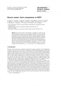
Forming the robust output signals of atomic clock ensembles is the actual problem for earth-based GNSS supply systems as well as for on-board satellite systems. The effective solution to the problem is to use an auxiliary voltage controlled oscillator (VCO) which is steered to the average frequency of clock ensemble (Fig. 1). This approach allows detecting clock failures and excluding frequency and phase jumps from the output signal [1]. The disadvantage of the simple frequency averaging concerns the necessity for using atomic clocks with comparable frequency stability characteristics (for different averaging times) otherwise the stability of the output signal would be spoiled by the signals with worse stability.
Clock 1
Clock N
Frequency Comparator
BIOGRAPHIES
I.
…
Abstract – We present the algorithm for frequency control of an auxiliary crystal oscillator to produce the output signal of ensemble which contains clocks with different frequency stability characteristics on different averaging times. By means of modeling it is shown that frequency stability of the output signal is close to the optimal for considered wide range of averaging times.
Processor
Voltage Controlled Oscillator Output
Figure 1: Frequency combining scheme in atomic clock ensemble Simple weighting of reference clocks inverse proportional to the Allan variances corresponding to each clock allows minimizing output signal frequency instability only at selected averaging time (which is used for weights calculation). Let us consider the integral part of digital automatic frequency control, the increment of the frequency control is:
N
∆U k = − ∑ wnS, k y nS, k ,
(1)
VCO f kVCO + K ⋅ ∆U k . +1 = f k
(2)
n =1
S
In (1) yn is the relative frequency difference between auxiliary voltage controlled oscillator and the S n-th reference clock, wn is the corresponding weight S coefficient. Time interval of control and yn estimation S τ should be selected less than the minimal averaging S time τw for which output signal frequency instability is minimized. Below we describe the simple modification of (1) which allows minimizing output signal frequency instability for a range of averaging times. II.
The algorithm is based on simultaneous estimating of relative frequency differences between slave oscillator and reference atomic clock signals in moving frames for two different averaging times (short time and long time, these values depend on frequency stability characteristics of reference signals). Frequency control is constructed as the sum of short-term control for compensation of fast frequency fluctuations and longterm control for correction of slow frequency drifts. The modified frequency control increment can be written in the following equivalent forms:
(
N
)
∆U k = − ∑ wnS, k y nS, k − y nL, k −
(3)
N
∑ wnL, k y nL, k (4)
n =1 n =1 L In (3), (4) yn,k is the relative frequency difference L L estimation for “long” averaging time τ . Note, that yn,k is estimated in moving frame and it can be updated for each control iteration k (as a matter of fact it can be L recalculated not so frequently). Weight coefficient wn is selected to be inverse proportional to the Allan variance of the n-th reference signal for averaging time L L L S τw , τw > τ . Weight coefficient wn is inverse proportional to the corresponding Allan variance for S S S averaging time τw , τw > τ . The algorithm is supposed to minimize the output S signal frequency instability at the averaging times: τw L S L and τw . But at the averaging times τ and τ the Allan variance of the output signal should be worse than the possible minimum due to the effect of control. It is easy to extend the algorithm for greater number of time intervals for frequency control and minimization of the output signal Allan variance. Three time scales frequency control can be written as follows:
N
(
N
(
)
∆U k = − ∑ wnS, k y nS, k − y nL, k − n =1
−
THE ALGORITHM DESCRIPTION
N N L L ∆U k = − ∑ wnS, k y nS, k − ∑ wm y , k nm, k n =1 m =1
It is especially important for Hydrogen masers which are known to present stable frequency drifts for long observing times. Let us assume that frequency drifts dn,k are known a priori or can be estimated by means of Kalman filter. The modification of equation (4) is the following:
∑ wnL, k (y nL, k − Dn, k ) N
(6)
n =1
D n , k +1 = D n , k + d n , k ⋅ τ S To increase the weight coefficients of reference clocks which possess stable frequency drift and low random walk and random run frequency modulation it is L proposed to select wn inverse proportional to Hadamard variance or to Allan variance calculated for data with frequency drift compensation. III. RESULTS OF MODELLING Let us consider two groups of reference clocks (4 clocks of each group) with different short-term and long term frequency instability characteristics marked as 1 and 2 in Fig. 2. We use discrete model for atomic clock noises to take into account white phase and frequency modulation, and random walk frequency modulation [2]. We also applied inverse Fourier transform method to model flicker frequency noise [3]. Frequency noise of controlled oscillator is modelled with parameters usual for BVA crystal oscillators. For real-time estimating of weight coefficients for two averaging times we calculate Allan variances by means of N-corner hat method [4] with overlapping samples.
)
∆U k = − ∑ wnS, k y nS, k − y nL, k − n =1
−
∑ wnL, k (y nL, k − y nL,2k ) − ∑ wnL,2k y nL,2k N
N
n =1
n =1
(5)
The two time scales frequency control represented by equation (4) can be modified to include the information about frequency drifts of reference signals.
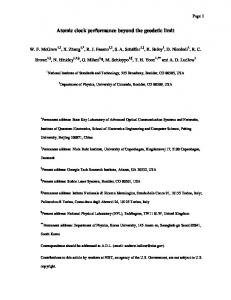
Figure 2: Result of modelling of two scales automatic frequency control The following time intervals for control are used: S S L τ = 1 s, τw = 10 s, τ = 1200 s (corresponds to the cross section of curves 1 and 2 in Fig. 2), L τw = 25000 s.
The resulting Allan variance for auxiliary oscillator stabilized by reference signals according to the two scales algorithm (4) is represented by the curve 3 in Fig. 2. Curve 4 in Fig. 2 corresponds to the Allan variance of the weighted average frequency of the reference clocks. This Allan variance is minimized for each averaging time by means of weights adjustment. This curve is considered to be the theoretical minimum for frequency instability of considered atomic clock ensemble.
Moreover, the Allan variance for the output signal is close to the theoretical minimum for corresponding atomic clock ensemble. IV. CONCLUSIONS There are a number of well-known time scale algorithms [2], based on Kalman filter mainly. These algorithms could be applied for steering an auxiliary oscillator frequency to produce output signal of an atomic clock ensemble. The main distinctive advantage of the approach presented in this paper seems to be its simplicity. Authors tried to suggest the easiest way to modify frequency averaging, realized in atomic clock frequency combiner VCH-317, to improve the quality of the output signal. This aim has been achieved. The method can be realized in a single device with limited computing power. We suppose that this method is better appropriate to fully automated quite simple ensemble clock systems. ACKNOWLEDGMENT Authors appreciate the helpful discussions with colleagues and the support from the company direction. REFERENCES
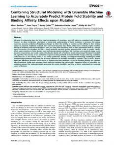
Figure 3: Result of modelling of three scales automatic frequency control; 1, 2, 3 – Allan variances for reference atomic clocks, 4 – Allan variance for controlled oscillator, 5 – theoretical minimum for atomic clock ensemble Fig. 3 shows the result for three time scales control algorithm (5). In this modelling three groups of oscillators with qualitatively different frequency instability characteristics are used. Results in Fig. 2 and Fig. 3 approve that the algorithm allows obtaining output signal of atomic clock ensemble with frequency instability characteristics better than the best reference clock has for all considered averaging times.
[1] http://www.vremya-ch.com/english/product/index012b.html ?Razdel=2&Id=30 [2] J. Levine The statistical modeling of atomic clocks and the design of timescales. Review of scientific instruments. 2012. V. 83. P. 021101 [3] Greenhall C.A. FFT-based methods for simulating flicker FM. Proceedings of the Precise Time and Time Interval (PTTI) Meeting. 2002. V. 34. P. 481-491 [4] Chernyshev I.N. and Mishagin K.G. Optimal measurement of frequency instability in a multi-channel comparator. Measurement Techniques. 2009. V. 52. N. 9. P. 931-939