parently break these queries into local subqueries based on metadata, send the .... more local (SQL) subqueries, by taking into account the ontology, the data ...
Quete: Ontology-Based Query System for Distributed Sources Haridimos Kondylakis1,2, Anastasia Analyti1, Dimitris Plexousakis1,2 1 Institute 2 Department
of Computer Science, FORTH-ICS, Greece of Computer Science, University of Crete, Greece {kondylak, analyti, dp}@ics.forth.gr
Abstract. The exponential growth of the web and the extended use of database management systems in widely distributed information systems has brought to the fore the need for seamless interconnection of diverse and large numbers of information sources. Our contribution is a system that provides a flexible approach for integrating and transparently querying multiple data sources, using a reference ontology. Global semantic queries are automatically mapped to queries local to the participating sources. The query system is capable of handling complex join constructs and of choosing the appropriate attributes, relations, and join conditions to preserve user query semantics. Moreover, the query engine exploits information on horizontal, vertical, and hybrid fragmentation of database tables, distributed over the various data sources. This optimization improves system's recall and boosts its effectiveness and performance. Keywords: Ontology-based data integration, mediation systems, query processing, table fragmentation rules
1. Introduction Data Integration is one of the key problems for the development of modern information systems. The exponential growth of the web and the extended use of database management systems has brought to the fore the need for seamless interconnection of diverse and large numbers of information sources. In order to provide uniform access to heterogeneous and autonomous data sources, complex query mechanisms have to be designed and implemented [16]. The design and implementation of a query mechanism is non-trivial because of the heterogeneity of the various components that are going to be queried. In this paper, we describe an ontology-based mediator system, called Quete, that provides a flexible approach for transparently integrating and querying multiple relational data sources. In particular, it provides full location, language, and schema transparency for users, and integrates dynamically heterogeneous (and possibly overlapping) relational data sources in evolving environments. A common reference ontology is used across integration domains and the data source-to-ontology annotation process, which follows the Local-as-View approach [3], is performed only once per data source. The motivation for this work was the integration of four database systems, in order to meet the needs of the PrognoChip project [13]. The aim of the project is to identify classification and prognosis molecular markers for breast cancer, through DNA mi-
croarray technology. Specifically, our task was to integrate two Clinical Information Systems that store clinical information about patients of two different hospitals and two Genomic Information Systems that store information on DNA microarray experiment settings and results. The objective was to provide a transparent layer that could enhance knowledge extraction and data exchange between these systems. Specifically, this layer should accept ontology-based queries from tools and users, transparently break these queries into local subqueries based on metadata, send the subqueries to the constituent databases, and integrate the returned results. Our system is an extension of a preliminary and incomplete version of Unity [10, 6], that provides the data source-to-ontology annotation mechanism and a local subquery formation algorithm. In particular, for each relational data source, a local annotator annotates (the interesting to the user) table attributes with paths over the reference ontology, called semantic names. We extended the local subquery formation algorithm that is provided by Unity, such that system’s recall is increased with no sacrifice in precision. Additionally, we implemented the composition of the local subquery. A novel feature of our system is that horizontal, vertical, and hybrid fragmentation rules about underlying schemata can be declared and used, increasing system’s recall and improving performance. In particular, we consider table fragmentation rules, during (i) the formation of the local subqueries, further extending Unity’s algorithm, and (ii) during the formation of the result composition plan. This assures that local subqueries are formed and composed in such a way that final results, presented to the user, are as if there was no table fragmentation. Further, system’s performance is optimized by eliminating local subqueries and avoiding joins in the result composition plan that are certain to return empty results. We want to note that our approach to data integration is by no means restricted to biomedical informatics. On the contrary, it is completely domain independent. The rest of the paper is organized as follows: Section 2 reviews related work on mediator-based data integration. In Section 3, our architecture is described, providing details about the data source-to-ontology mappings, the processing of the user semantic query, and the incorporation of the table fragmentation rules into the system. In Section 4, preliminary experimental evaluation of Quete is provided. Finally, Section 5 concludes the paper and gives directions for further research.
2. Related Work A mediator is a system that is responsible for reformulating, at runtime, a user query on a single mediated schema into a composition of subqueries over the local source schemas [7]. To achieve this, a mapping is required that captures the relationship between the local source descriptions and the mediator schema. Specifying this correspondence is a crucial step, as it influences both how difficult query reformulation is and how easily new sources can be added to or removed from the integration system. The two main approaches for establishing the mapping between each source schema and the global schema are the Global-as-View (GAV) and the Local-as-View (LAV) approaches (for an overview, see [3]). In short, in the GAV approach, each mediator relation is defined in terms of the data source relations, while in the LAV approach, data source relations are defined in terms of the mediator schema. Older projects that
2
follow the GAV approach are TSIMMIS [4] and DISCO [17], while Information Manifold [8] follows the LAV approach. Ontologies can be used as the global schema and it seems that database integration is currently evolving towards this direction. By accepting an ontology as a point of common reference, naming conflicts are eliminated and semantic conflicts are reduced. Below, we review a few recent ontology-based data integration projects. In BACIIS [2] and TAMBIS [15], a single conceptualization is provided trying to capture the information in the system data sources. User queries are built and results are returned in terms of this global conceptual schema. However, any change in the sources may require the modification of the global domain conceptualization. Additionally, in TAMBIS, the integration process is restricted to combine data from sources that contain different types of information for the same semantic entity. Thus, the potential overlapping aspect of the sources or the probable incompleteness of some of them is ignored. Moreover, BACIIS only integrates Web Databases and mappings are based on text parsing of web pages. In ONTOFUSION [1], separate conceptual schemas are used to describe the semantics of each data source. Every concept in a physical database is mapped to a virtual schema. Virtual schemas are ontologies representing the structure of the database at a conceptual level. Then, the various virtual schemas corresponding to the distinct databases are merged into new, unified virtual schemas that can be accessed by the users in order to form their queries. This approach adds more complexity to the whole task, but is otherwise promising. Java Application Java Application Query
Ontology
Result
Java DB Engine
Fragmentation Rules
Mappings Ontology
QUETE
Jdbc-Odbc
Source 1
Jdbc-Odbc
Source 2
Jdbc-Odbc
Source 3
Fig. 1. The integration architecture of Quete
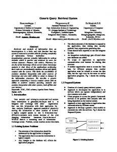
3. Integration Architecture Quete is an ontology-based mediator system capable of integrating relational databases in evolving environments (participating data sources can change their schema, their semantics, their portion of shared data, or exit without any concern about the other data sources). The architecture of the system is shown in Figure 1. A user (or Java application) issues a semantic query to a central site, that is expressed in terms of a reference ontology. Then, the system decomposes the semantic query to one or more local (SQL) subqueries, by taking into account the ontology, the data source-to-
3
ontology mappings, and the table fragmentation rules. The resulting subqueries are issued to the underlying databases, whose answers are sent back to the central cite. Then, the system integrates the results and the final answer is returned to the user. We have to note that no translational or wrapper software is required for the individual data sources, as the central site communicates directly with the data sources, using ODBC protocols. 3.1 Reference Ontology and Semantic Name Formulation In order to issue semantic queries and to map underlying attributes to a common point of reference, an ontology needs to be employed as a general schema. This reference ontology is used to describe schema semantics since it provides standardized names for concepts with unambiguous definitions. The idea is to map the shared schema elements of the sources to the reference ontology. In Quete, the reference ontology is organized as a graph of concepts that are related through two types of relationships; “IS-A” relationships and “HAS-A” relationships. “IS-A” relationships are used to model generalization/specialization of concepts, while “HAS-A” relationships are used to model component relationships. Each concept can have an associated set of attributes. Additionally, there is a special class of concepts, called relationship concepts, modeling generic relationships. To represent ontologies like these, we could use the web-ontology languages RDFS [5] and OWL [11], whereas it is important to understand that the exact organization of the concept hierarchy and the terms used to represent concepts is irrelevant as long as they are agreed upon. Although this is a rather simple modeling mechanism, we believe that it is adequate for capturing real-world schemas, since any general relationship can be represented as a concept. Using a reference ontology, we can form the semantic name of a table as: SN = [CNpath] = [CN1; ...; CNm], and the semantic name of an attribute as: SN = [CN1; ...; CNm] AN, where CNi , i = 1, ..., m, are concepts of the reference ontology and AN is a (possibly inherited) attribute of concept CNm. The semi-colon between concepts CNi and CNi+1 means that concept CNi “HAS-A” (generalization of) concept CNi+1, i=1, ..., m-1. Intuitively, the semantic name of a schema element (table or attribute) captures its semantics w.r.t. the reference ontology. We say that a semantic name [CN1; ...; CNm] is subsumed by a semantic name [CN’1; ...; CN’m’] if (i) m’ ≤ m, (ii) CNm-m’+i coincides with or is a specialization of CN’i, i=1, ..., m’. Moreover, we say that a semantic name [CNpath] AN is subsumed by a semantic name [CN’path] AN’, if (i) [CNpath] is subsumed by [CN’path], and (ii) AN=AN’. Intuitively, a semantic name SN is subsumed by a semantic name SN’, if its semantics is the same or more specific than the semantics of SN’. We say that two semantic names are semantically overlapping, if (i) their last i (for an i > 0) concept names (CN) are the same or related through the "ISA" relationship, and (ii) they have the same attribute name (AN). Additionally, we say that two schema elements are semantically overlapping, if their corresponding semantic names are semantically overlapping. Obviously, if a semantic name sn is subsumed by a semantic name sn’ then sn and sn’ are semantically overlapping.
4
RiskFactors
Reporter
GOAnnotation
YearsOfSmoking : Int Age : Int
ReporterName :String HGNCGeneSymbol :String
GOId GOName
BreastCancerPatient Name City SSN
: String : String : String
: String : String
GeneExpression RatioValue
: Decimal GOBiologicalProcess
GOMolecularFunction
GOCellularComponent Hybridization TumorSample TumorIdentifier SurgeryDate
HybridizationDate: Date IS-A
: String : Date
HAS-A
Fig. 2. An example biomedical ontology in UML
As a running example, consider the simple biomedical ontology of Figure 2 that describes the following scenario: Each Patient with breast cancer is associated with some Risk Factors, such as smoking habits, age, etc. After undergoing surgery, her Tumor is removed and sent to a molecular biology laboratory for taking part in a gene expression profiling experiment, based on the (spotted) DNA microarray technology1. In these experiments, fragments of genes, called Reporters, are spotted on a microarray slide, which is hybridized with the cancerous tissue and a “normal” tissue. Hybridization results are analyzed to generate Gene Expression data, expressing through a Ratio Value (per spotted gene), if the gene in the cancerous tissue is over-expressed, under-expressed, or equally expressed with respect to the “normal” tissue. In other words, the gene expression profile of the tumor is compared with that of a “normal” tissue. Gene Ontology (GO) is a well-known ontology for the annotation of gene products in terms of the biological processes in which they participate, the particular molecular functions that they perform, and the cellular components in which they act (see http://www.geneontology.org). In particular, GO consists of 3 independent taxonomies, namely GO Biological Process, GO Molecular Function, and GO Cellular Component. In our example ontology, reporters are annotated with the GO terms (i.e., GO ids and their corresponding GO names) that characterize the gene products of the gene that the reporter is part of. Note that according to our example ontology, GeneExpression is a relationship concept, whose instances relate a hybridization with a reporter and a ratio value, and RatioValue is an attribute of GeneExpression. Adittionally, note that (i) [Hybridization; TumorSample] TumorIdentifier is a valid semantic name, representing the tumors participating in hybridization experiments, and (ii) [Reporter; GOBiologicalProcess] GOName is a valid semantic name that is subsumed by (and semantically overlaps with) [GOAnnotation] GOName. Assume now that we want to integrate a Clinical and a Genomic database, using our example ontology. In Table 1, we give the semantic names of some of the Clinical and Genomic database schema elements (tables/attributes). Note that the atrributes SurgicalExcision.TumorSampleId and Hybridization.CancerousTissue are semanti1
http://www.ncbi.nlm.nih.gov/About/primer/microarrays.html
5
cally overlapping. Of course, internal database IDs, such as BreastCancerPatient.PatientId, do not have semantic names. Table 1. Clinical and Genomic database schema elements and their semantic names Type
System Name
Semantic Name [BreastCancerPatient; RiskFactors] [BreastCancerPatient; RiskFactors] Age [BreastCancerPatient; RiskFactors] YearsOfSmoking [BreastCancerPatient] [BreastCancerPatient] Name [BreastCancerPatient] City [BreastCancerPatient] SSN [BreastCancerPatient; TumorSample] [BreastCancerPatient; TumorSample] TumorIdentifier [BreastCancerPatient; TumorSample] SurgeryDate [Hybridization] [Hybridization; TumorSample] TumorIdentifier [Hybridization] HybridizationDate [GeneExpression] [GeneExpression; Reporter] ReporterName [ GeneExpression] RatioValue [Reporter] [Reporter] ReporterName [Reporter] HGNCGeneSymbol [GOMolecularFunction] [GOMolecularFunction;Reporter] ReporterName [GOMolecularFunction] GOId [GOMolecularFunction] GOName
Genomic Database Schema
RiskFactors PatientId Age YearsOfSmoking BreastCancerPatient PatientId Name City SSN SurgicalExcision PatientId TumorSampleId SurgeryDate Hybridization HybridizationId CancerousTissue Date GeneExpressionData HybridizationId ReporterId Value Reporter ReporterId GeneSymbol ReporterGOMolFun ReporterId GOId GOName
Clinical Database Schema
Table Attribute Attribute Attribute Table Attribute Attribute Attribute Attribute Table Attribute Attribute Attribute Table Attribute Attribute Attribute Table Attribute Attribute Attribute Table Attribute Attribute Table Attribute Attribute Attribute
The data source-to-ontology annotation phase is used to capture the data to be integrated and is performed independently in each local data source. The Extractor tool of Unity [10, 6] is used to extract the underlying database schema (i.e., tables, attributes, foreign keys, primary keys). The extracted schema is then stored in a specific XML file, called X-Spec. Then, the administrator selects the schema elements (tables/attributes) that are going to be shared, and annotates the interesting to the user schema elements with semantic names over the reference ontology. Subsequently, the final X-Spec is sent to the central site. Note that the data source-to-ontology annotation follows the Local-as-View approach [3]. Obviously, a data source is capable to change the schema, the semantics, and the portion of the data to be shared by just altering its X-Spec file. 3.2 Query Processing in Quete After specification of the X-Spec files, the user is given the capability to issue semantic queries. The query language is an attribute-only language similar to SQL, where the SELECT clause contains the terms to be projected in the final results and the op-
6
tional WHERE clause specifies selection criteria for the query. Continuing our running example, a user query, quser, requesting “the expression ratio value of genes, whose molecular function is “cell adhesion” and are expressed in (the tumor of) breast cancer patients that (i) have smoked for more than 30 years and (ii) their surgery date is the same with the date of the hybridization experiment” is: SELECT [BreastCancerPatient]Name, [Reporter]HGNCGeneSymbol, [GeneExpression]RatioValue WHERE [RiskFactors]YearsOfSmoking>30 AND [Hybridization]HybridizationDate = [TumorSample]SurgeryDate AND [Reporter;GOMolecularFunction]GOName=“cell adhesion” ORDERBY [BreastCancerPatient]Name
Of course, the user must express the query terms through their semantic names. Notice that, in the semantic query, the FROM clause is absent. This is because, query concepts appear within semantic names. During query processing, the system automatically identifies the local tables that will be accessed and the joins that are needed to link together the various interesting to the user parts of distributed information. For the time being, Sub-selects and Union operations are not supported in the query language, while Order and Group operations are. After submission, the user semantic query is translated to SQL subqueries that are issued in parallel to the underlying data sources. There are three major requirements in forming a local subquery: Requirement 1: The system must identify the interesting to the user table attributes. We consider that a table attribute T.A with semantic name [CNpath] AN is interesting to the user, in the following cases: Case 1: [CNpath] AN is semantically subsumed by a semantic name sn appearing in the user query. Thus, the attribute T.A carries the same of more specific information than that requested by the user. Case 2: [CNpath] AN semantically overlaps with a semantic name sn appearing in the user query and it exists a table T’ whose semantic name [CN’path] is such that (i) the tables T and T’ share the same primary key, and (ii) [CN’path] AN is subsumed by [CNpath] AN and sn. Case 2 captures a common representation of the “IS-A” relationship in relational databases. Intuitively, the meaning of table T’ is a specialization of that of T, and thus, T’ inherits attribute A from T. Case 3: there is a sequence of tables (T1, ..., Tm, T), such that (i) neighbour tables in the sequence can be joined based on foreign key information, and (ii) the semantic names [CN1path], ..., [CNmpath] of T1, ..., Tm , respectively, are such that the semantic name [CN1path; ...; CNmpath; CNpath]2 AN is subsumed by a semantic name sn appearing in the user query. The idea behind this case is that the information requested by the user, as expressed in sn, can be retrieved through the appropriate joins between local tables with related semantics. Requirement 2: As the FROM clause is missing from the user semantic query, the required intermediate tables, linking the tables with interesting to the user attributes (and in Cases 2 and 3, above, also the tables T’ and T1, ..., Tm, respectively) must be determined by the system. Additionally, the system must determine the conditions that are required to join these tables. 2
If two neighbour concepts names in CN1path; ...; CNmpath; CNpath are the same then only one is kept.
7
Requirement 3: Assume that s, s’ are two local sources such that the interesting to the user attributes, identified in these sources, do not semantically overlap. Then, the local subqueries submitted to s and s’ should provide the (join) attributes, called DB link attributes, that are needed to link the interesting to the user attributes that are provided by the two data sources. To achieve these requirements, our system inspects the reference ontology and the XSpec files (for retrieving the data source-to-ontology mappings and information on foreign keys). The (intermediate) join tables, needed to satisfy Requirement 2 above, are decided based on an algorithm that is provided by Unity [6], which links a set of tables by forming a local join tree. A local join tree is a connected undirected graph whose nodes correspond to database tables and there is a link between two nodes if there is a join (based on foreign keys) between the corresponding two tables. All identified tables are joined by (i) enforcing equality on their attributes that correspond to pairs 〈foreign key, primary key〉, and (ii) enforcing the conditions in the WHERE clause of the user query that can be checked locally. To satisfy Requirement 3, our system proceeds as follows: Let s, s’ be two local sources such that the interesting to the user attributes, identified in these sources, do not semantically overlap. Let TS and TS’ be the sets of tables of s and s’, respectively, that have been identified in order to satisfy Requirements 1 and 2, above. Our system inspects TS and TS’, and if it finds a pair of attributes T.A and T’.A’ (T ∈ TS and T’ ∈ TS’) that are semantically overlapping then it includes them in the local subqueries to s and s’, respectively. These attributes will be used for joining the local subqueries to s and s’, at result composition time. Based on the above analysis, our local subquery formation algorithm builds one SQL subquery, for each data source. This SQL subquery provides all the attributes of the local source that are interesting to the user, plus the DB link attributes (if any). We want to note that Unity considers as interesting to the user only the attributes whose semantic names appear in the user query. This is a subcase of Case 1, above. Thus, in Unity, an attribute whose semantic name semantically overlaps, but is not the same, with a semantic name in the user query is ignored. Moreover, Unity does not take care of Requirement 3. When the results from the local subqueries are returned to the central site, they are composed based on a result composition plan, that is formed using Join, Union, and Projection operations, while, if needed, operations Group and Order are applied at the end. After execution of this composition plan on the local subquery results, final results are presented to the user. Continuing our running example, consider a Clinical database (DB1) with tables RiskFactors, BreastCancerPatient, and SurgicalExcision, and a Genomic database (DB2) with tables Hybridization, GeneExpressionData, Reporter, and ReporterGOMolFun. After describing the attributes of these tables using our example ontology, as shown in Table 1, the corresponding X-Spec files are sent to the central site. Assume now that the user query quser is issued. Checking the corresponding X-Spec files, it is concluded that the attributes BreastCancerPatient.Name, RiskFactors.YearsOfSmoking, SurgicalExcision.SurgeryDate, and SurgicalExcision.TumorSampleId should appear in the SELECT clause of the Clinical database subquery. The first attribute is needed to be presented to the user, the second and third to satisfy the condition in the WHERE
8
clause of the user query, and the fourth (which is a DB link attribute) is needed to join this local subquery with that submitted to the Genomic database. The local join tree that connects the tables BreastCancerPatient, RiskFactors, and SurgicalExcision is: RiskFactors – BreastCancerPatient – SurgicalExcision. Similarly, the attributes Reporter.GeneSymbol, GeneExpressionData.Value, Hybridization.Date, ReporterGOMolFun.GOName, and Hybridization.CancerousTissue should appear in the SELECT clause of the Genomic database subquery and the corresponding local join tree is: Hybridization – GeneExpressionData – Reporter – ReporterGOMolFun. Then, the system forms the following two subqueries, q1 and q2, that will be issued to the local databases DB1 and DB2, respectively. DB1: SELECT BreastCancerPatient.Name, RiskFactors.YearsOfSmoking, SurgicalExcsion.SurgeryDate, SurgicalExcsion.TumorSampleId FROM RiskFactors, BreastCancerPatient, SurgicalExcision WHERE RiskFactors.YearsOfSmoking>30 AND RiskFactors.PatientId=BreastCancerPatient.PatientId AND BreastCancerPatient.PatientId=SurgicalExcision.PatientId DB2: SELECT Reporter.GeneSymbol, GeneExpressionData.Value, Hybridization.Date, ReporterGOMolFun.GOName, Hybridization.CancerousTissue FROM Hybridization, GeneExpressionData, Reporter,ReporterGOMolFun WHERE Hybridization.HybridizationId = GeneExpressionData.HybridizationId AND GeneExpressionData.ReporterId = Reporter.ReporterId AND Reporter.ReporterId= ReporterGOMolFun.ReporterID AND ReporterGOMolFun.GOName= “cell adhesion”
The above subqueries q1 and q2 are issued in parallel to the Clinical and Genomic database, respectively, using threads. Note that, the condition [RiskFactors]YearsOfSmoking>30 (resp. [Reporter;GOMolecularFunction]GOName=“cell adhesion”), appearing in the WHERE clause of the user query quser, is checked in q1 (resp. q2). However, the condition [Hybridization]HybridizationDate = [TumorSample]SurgeryDate cannot be checked in a local subquery alone. Our algorithm for forming the result composition plan is given below (Alg. 3.1). We want to note that Alg 3.1 does not have to search the XSpec files or the reference ontology, as all the information that it requires from these sources has already been retrieved during the formation of the local subqueries. In Section 3.3, we describe how Alg 3.1 is extended, in the case that knowledge on table fragmentation exists. Algorithm 3.1. ResultCompositionPlan(quser, QS) Input: (i) the user semantic query, quser, and (ii) the local subqueries QS = {q1, …, qn} Output: Composition plan for the local subquery results 1: For i := 1, ..., n do { Let the projection attributes of qi be the attributes returned by qi; } /* End For */ 2: Let {S1, ..., Sk} be all the minimal subsets of QS such that: (i) for each semantic name sn appearing in quser, there is a projection attribute of a subquery in Si, whose semantic name semantically overlaps with sn, (ii) for each subquery in Si, there is a projection attribute which does not semantically overlap with a projection attribute of another subquery in Si, and (iii) there is global join tree connecting all subqueries of Si, i = 1, ..., k;
9
3: For i := 1, ..., k do { 3.1 Join the local subqueries in Si, by forcing equality on their semantically overlapping projection attributes and applying the user specified conditions, not already applied to the local subqueries in Si; /* Join semantically overlapping subqueries and apply user specified conditions */ 3.2 Project the new subquery pi to the attributes whose semantic names semantically overlap with these in the SELECT, GROUPBY, and ORDER clause of quser; } /* End For */ 4: Union resulting subqueries pi’ (for i = 1, ..., k) by aligning their semantically overlapping attributes; /* Union pi’, i = 1, ..., k and produce a single subquery */ 5: Apply to the resulting subquery, the Group and Order operations (if any) indicated in quser; 6: Return the formed result composition plan, after usual optimization techniques are applied;
In Alg. 3.1, input local subqueries are placed in QS. The projection attributes of each local subquery q are defined as the attributes returned by q (Step 1). Local subqueries having projections attributes that are semantically overlapping are called semantically overlapping. A global join tree is a connected undirected graph whose nodes correspond to local subqueries and there is a link between two nodes, if their corresponding local subqueries are semantically overlapping. We consider that semantically overlapping subqueries represent information that overlaps on their semantically overlapping projection attributes, and thus they should be joined. Step 2 computes all the minimal subsets Si, i= 1, ..., k, of QS such that: (i) for each semantic name sn appearing in the user query, there is a projection attribute of a subquery in Si, whose semantic name semantically overlaps with sn, (ii) for each subquery in Si, there is a projection attribute which does not semantically overlap with a projection attribute of another subquery in Si, and (iii) there is a global join tree connecting all subqueries in Si. The reasoning behind Step 2 is that the answers returned to the user should be correct and provide all requested attributes. Then, local subqueries in Si, i= 1, ..., k, are joined by (i) forcing equality on their semantically overlapping projection attributes, and (ii) applying the user specified conditions, not already applied to the local subqueries in Si (Step 3.1). Each resulting subquery pi, i= 1, ..., k, is projected to the attributes whose semantics names semantically overlap with these in the SELECT, GROUPBY, or ORDER clause of the user query (Step 3.2). Subsequently, all resulting subqueries pi’, i= 1, ..., k, are unioned (Step 4). Finally, Group and Order operators are applied, as indicated in the user query (Step 5). Note that due to conditions (i) and (ii) of Step 2, it holds that for each i= 1, ..., k, |Si| ≤ r , where r is the number of different semantic names appearing in the user query. Additionally, note that although there is no j ≠ i, such that Si ⊆ Sj, for i, j= 1, ..., k, local subquery sets Si can be overlapping. Thus, the result composition plan can be optimized by first joining common subqueries and then, proceeding to further joins that use the result. Alg. 3.1 returns the optimized result composition plan (Step 6). Continuing our running example, the set S1={q1, q2}, where q1 and q2 are the local subqueries submitted to DB1 and DB2, respectively, satisfies the conditions of Step 2 of Alg 3.1. Thus, subqueries q1 and q2 are joined based on the conditions (i) SurgicalExcision.TumorSampleId = Hybridization.CancerousTissue, and (ii) SurgicalExcision.SurgeryDate = Hybridization.Date (see Step 3.1). Note that condition (i) is due
10
to the fact that attributes SurgicalExcision.TumorSampleId, Hybridization.CancerousTissue are semantically overlapping, while condition (ii) is due to the user specified condition [Hybridization]HybridizationDate = [TumorSample]SurgeryDate. The resulting query p1 is then projected to the attributes BreastCancerPatient.Name, Reporter.GeneSymbol, and GeneExpressionData.Value that are interesting to the user (see Step 3.2) and results are ordered based on BreastCancerPatient.Name (See Step 5). The composition of the local subquery results is done with the help of a central DBMS and consists of the following five steps: 1. 2. 3.
4. 5.
For every subquery issued to a local data source, design the temporary table that will be constructed in the central database to store the returned results. Build these tables in the central (lightweight) database. Build the global SQL query that will be issued to the central database, according to the result composition plan formed by Alg. 3.1 (in the result composition plan, local subqueries are replaced by their corresponding temporary tables). Store the local subquery results into the temporary tables, created in Step 2. Execute the global SQL query (formed in Step 3) over the temporary tables, get the results, and present them to the final user.
The first four steps are executed in parallel, using threads. As the global SQL query is issued to the central database, Join, Union, Order, and Group operations are executed by the central DBMS. 3.3 Considering Table Fragmentation Rules In Quete, we take into account information on horizontal, vertical, and hybrid table fragmentation [12], where table fragments are distributed over the various data sources. This consideration improves system’s recall and optimizes performance. In our case, horizontal fragmentation is based on a defining condition, which is a boolean expression (in conjunctive normal form) of simple conditions: “Attr comparison-operator Value”, where Attr is an attribute, comparison-operator is one of , =, ≤, ≥, ≠, and Value is a number, or string. For example, consider the table BreastCancerPatient(PatientId, Name, City, SSN). A horizontal fragmentation of this table could result to two fragments. The first fragment contains tuples with PatientId < 500 and is stored in DB1, while the second contains tuples with PatientId ≥ 500 and is stored in DB2. Moreover, the system supports vertical fragmentation. For example, vertical fragmentation of the table BreastCancerPatient could result to three fragments. The first fragment with attributes PatientId and Name is stored in DB1, the second with attributes PatientId and City is stored in DB2, and the third with attributes PatientId and SSN is stored in DB3. We also support hybrid fragmentation, which is a tree-structured partitioning of a table, formed by successive horizontal and vertical fragmentations, or vice-versa. The tables that result after the application of horizontal, vertical, and hybrid fragmentation are called horizontal, vertical, and hybrid fragments, respectively. Hybrid fragments are associated with a condition which is the conjunction of the defining conditions of the horizontal fragmentations through which they have been derived (if any) or true. The rules that describe table fragmentation are called table fragmentation rules and stored in an XML file in the central site.
11
Extending our local subquery formation algorithm, we consider table fragmentation rules during the formation of the local subqueries. Specifically, assume that (N,E) is the local join tree, identified for forming a local subquery in the case that no knowledge on table fragmentation exists. Then, if an f∈N, refers to a table fragment, our algorithm forms one subquery qf querying only f, and another subquery qr querying the rest of the tables in N, keeping in the SELECT clause of qr the foreign key that will connect qf with qr, at result composition time. Table fragmentation rules are also checked during the formation of the result composition plan. The reason is that fragments of the same table t (containing information interesting to the user) should be composed through the appropriate Join and Union operations before any further processing, so that final results (presented to the user) are the same as if t had never been fragmented. An additional benefit from using horizontal and hybrid fragmentation rules is that the system may be able to predict that the execution of certain subqueries on table fragments will return empty results, and thus avoid their execution, optimizing performance. In Quete, horizontal and hybrid fragmentation rules are checked, each time a generated local subquery refers to a horizontal or hybrid table fragment. If the fragment’s associated condition conflicts with that in the WHERE clause of the local subquery then the subquery is discarded. Continuing our running example, consider another Clinical database (DB4) with the table Breast_cancer_patient(PatientId, Name, City, SSN, Age, YearsOfSmoking), but with no information about surgeries. Thus, our integrated environment now includes the sources DB1, DB2, DB3, and DB4. Assume now that a table PatientWithBreastCancer, containing information about breast cancer patients in the whole prefecture of Heraklion, has been (at some time) fragmented horizontally into two fragments. The first with defining condition= is stored in DB1 and the second with defining condition= is stored in DB4 and is the table Breast_cancer_patient. Assume now that the first fragment is further fragmented vertically (for reasons of perfomance) into two fragments that are the tables BreastCancerPatient and RiskFactors. Note that all tables BreastCancerPatient, RiskFactors, and Breast_cancer_patient are hybrid fragments of the same table, the first two with associated condition and the third with associated condition . Assume now that the user poses the semantic query quser of our running example. If no knowledge about this hybrid fragmentation exists, information about tumor surgeries (and thus, about the gene expression profiles) of breast cancer patients that do not live in the city of Iraklion will be lost. This is because, (i) all projection attributes of the local subquery, issued to DB4, semantically overlap with a projection attribute of the local subqueries q1 and q3, and (ii) there is no way to link the clinical information that is stored in DB4 with the genomic information stored in DB2. If, however, knowledge about this hybrid fragmentation exists, the system can combine the table fragments to reconstruct the original table PatientWithBreastCancer and then, take its join with the table SurgicalExcision of DB1 (based on foreign key information). This way there will be no information loss, and interesting gene expression information about breast cancer patients, living in the whole prefecture of Heraklion, will be retrieved.
12
To support knowledge on horizontal, vertical, and hybrid table fragmentation, Alg. 3.1 is extended by adding after Step 1, the statement QS = CombineFragments(QS). The algorithm CombineFragments(S) (Alg. 3.2) takes as input a set of local subqueries S and combines the table fragments in S, so as to reconstruct the original tables. Then, it joins the original tables t with the other subqueries issued to the local sources of the fragments of t. Thus, there will be no information loss due to the fact that table fragments are distributed over the various data sources. Algorithm 3.2. CombineFragments(S) Input: a set of local subqueries S={q1,...,qn} Output: a new set of subqueries that recombine fragmented tables and proceed to useful joins 1: For i :=1,…,n do { Let DBs(qi) be a singleton set with the local source of qi; } /* End For */ 2: Let FS be the local subqueries in S that refer to table fragments; 3: Let {S1, …, Sk} be maximal subsets of FS such that all subqueries in Si , for i =1, …, k, refer either (i) to vertical fragments of the same table or (ii) to hybrid fragments of the same table such that their associated conditions are not conflicting; 4: For i :=1, …, k do { Join the subqueries in Si, by forcing equality on their primary key; Let the projection attributes of the resulting subquery q be the union of the projection attributes of the subqueries in Si, keeping from the common primary keys only one; FS := (FS – Si) ∪ {q}; DBs(q) := ∪{DBs(q') | q' ∈ Si}; } /* End For */ 5: Let {S1, …, Sk} be maximal subsets of FS such that all subqueries in Si, for i =1, …, k, refer either to horizontal fragments of the same table or to hybrid fragments of the same table; 6: For i :=1,…,k do { Take the union of the subqueries in Si; Let the projection attributes of the resulting subquery q be the projection attributes of one of the subqueries in Si; FS := (FS – Si) ∪ {q}; DBs(q) := ∪{DBs(q') | q' ∈ Si}; } /* End For */ 7: FS' :=FS; S' :=S - FS; /* Initialize FS' and S' */ 8: For each subquery q ∈ FS do { /* Join reconstructed tables with other local subqueries */ For each subquery q' ∈ S - FS do { /* q' is a local subquery */ If DBs(q') ⊆ DBs(q) then { Join q' and q based on foreign key information between (i) the tables appearing in q' and (ii) the table fragments appearing in q and stored in DBs(q'); Let the projection attributes of the resulting subquery q" be the union of the projection attributes of q and q', removing the foreign key used in the join; FS' := FS' - {q}; S' := (S' - {q'}) ∪ {q"}; } } /* End For */ } /* End For */ 9: Return(S' ∪ FS' );
In Step 4, the vertical and hybrid fragmentation rules are considered and all (i) vertical fragments of the same table, and (ii) hybrid fragments of the same table, such that their associated conditions are not conflicting, are joined. Note that subquery sets Si, for i =1,…, k, can be overlapping if they refer to hybrid fragments of the same table. Additionally, note that all subqueries in Si, for i =1, …, k, are local and, as they refer to vertical and hybrid fragments of the same table, have common primary keys.
13
In Step 6, only the horizontal fragmentation rules are considered and all horizontal fragments of the same table are unioned. Additionally, in Step 3.2, all subqueries created in Step 3.1 that refer to hybrid fragments of the same table are unioned (fully reconstructing the original table). Note that in Step 6, all subquery sets Si, for i=1, …, k, are pairwise disjoint and all subqueries in Si, for i=1, …, k, have common projection attributes. Thus, vertically fragmented tables are reconstructed through Step 4, horizontally fragmented tables are reconstructed through Step 6, and hybrid-fragmented tables are reconstructed through both steps 4 and 6. Then, Alg. 3.2 joins the subqueries that reconstruct the original tables t with the other subqueries issued to the local sources of fragments of t. The join is based on foreign key information, identified during the formation of the local subqueries. In our example, the subquery that reconstructs the original table PatientWithBreastCancer is formed by (i) a join on the fragments stored in DB1 (by enforcing equality of their PatientId attributes), and (ii) a subsequent union of the result with the fragment stored in DB4. The resulting subquery is then joined with the second subquery submitted to DB1: SELECT PatientId, TumorSampleId, SurgeryDate FROM SurgicalExcision by forcing equality on the PatientId attributes of the two subqueries. Finally, we would like to mention that considering table fragmentation rules, unnecessary joins (in Step 3.1 of Alg 3.1) between local subqueries, that refer to fragments of the same table and have conflicting associated conditions, are avoided. Thus, performance is improved.
4. Preliminary Performance Evaluation To evaluate Quete, we performed several experiments. Here, we present the evaluation conducted for the needs of the PrognoChip project. Our resources were limited, thus we used only four machines with an Intel Pentium 4 processor on 3.4 GHz, and 2 GB of RAM. In particular, for our experiments, we used four SQLServer local databases (two Clinical and two Genomic). The two Clinical databases capture patient clinical information of two Hospital environments. The first Genomic database is dedicated to DNA microarray experiment settings, and the second one to the storage of gene expression profiles of tumors, participating in microarray experiments. In these two Genomic databases, there exist two horizontal fragments of the same table. The schema of each database was annotated using a reference ontology, designed by us. In our study, we issue a user semantic query that uses around 10 tables from each database. Our central database also uses SQLServer and resides at the same machine as one of the Clinical databases. To evaluate our system, we have built a benchmark program that loads local tables with a prefixed number of rows. In Figure 3, the performance results of four experiments are shown. In the first two experiments (denoted by, 3DBs fragment, 3DBs no fragment), we used three databases (one Clinical and two Genomic), with and without considering table fragmentation rules, respectively. In the last two experiments (denoted by, 4DBs fragment, 4DBs no fragment), we used all four databases (two Clinical and two Genomic), again with and without considering table fragmentation rules, respectively. We see that the whole system has an acceptable performance, even with large data sets and
14
complex queries. Moreover, knowledge on table fragmentation improves the performance of the system.
Time (sec)
100
4DBs no fragment
90
4DBs fragment
80
3DBs no fragment
70
3DBs fragment
60 50 40 30 20 10 0 0
10000
20000
30000
40000
50000
60000
Rows
Fig. 3. Performance of Quete with and without knowledge on table fragmentation
In particular, let us define the elapsed time of a local subquery q, ETq, as the time from issuing q to the corresponding local source, until results are returned to the central site. Considering table fragmentation rules, a performance gain is achieved in the case that EThq > ETslq, where hq is a local subquery involving a conflicting horizontal fragment, and slq is the slowest local subquery that does not involve a conflicting horizontal fragment. This is because local subqueries are issued in parallel, thus the total elapsed time coincides with the elapsed time of the slowest subquery. Further, a performance gain is achieved at result composition time, since unnecessary joins between local subqueries, that refer to conflicting table fragments, are avoided.
5. Conclusions and Outlook Quete is an ontology-based mediator system that integrates several underlying relational databases by providing the user with the capability to transparently query them. Since every source relation is defined over the reference ontology, it follows the Local-as-View approach [3], and thus, can flexibly accommodate the addition/deletion and evolution of the local sources that participate in the integrated system. Moreover, underlying sources can evolve at will, without any changes to the reference ontology. Comparing with Information Manifold [8], which also follows the Local-as-View approach, our supported data source-to-ontology mappings are quite simple. However, we sacrifice expressiveness in order to achieve performance and easiness in use (both for local annotators and users). A novel feature of Quete is that rules concerning horizontal, vertical, and hybrid table fragmentation can be declared and used, increasing system’s recall and improving performance. To the best of our knowledge, no other ontology-based mediator system takes into account table fragmentation information.
15
Finally, we would like to note that our work does not claim to be complete and further performance evaluation experiments need to be performed. Our future plans also include the expansion of our implementation to non-relational data sources, and in particular, web databases with limited query capabilities (through wrappers). Moreover, we plan to enhance and ease the administrator’s task, by extending the schema mapping tool described in [9], such that the semantic names of the data source schema elements are generated semi-automatically and stored directly in the corresponding XSpec files. Acknowledgments. We would like to thank Ramon Lawrence for providing us with a preliminary version of Unity, which we used as a starting point in our research. References 1. 2. 3. 4. 5. 6. 7. 8. 9. 10. 11. 12. 13.
14. 15. 16. 17.
Alonso-Calvo, R., Maojo, V., Billhardt, H., Martin-Sanchez, F., Garcia-Remesal, M., Perez-Rey, D.: An agent- and ontology-based system for integrating public gene, protein, and disease databases. Journal of Biomedical Informatics, 40(1), pp. 17-29, 2007. Ben Miled, Z., Li, N., and Bukhres, O.: BACIIS: Biological and Chemical Information Integration Systems. Journal of Database Management, 16(3), pp. 73-85, 2005. Calvanese, D., Lembo, D., and Lenzerini, M.: Survey on methods for query rewriting and query answering using views. Technical Report D1.R5, Dipartimento di Informatica e Sistemistica, Università di Roma "La Sapienza", April 2001. Garcia-Molina, H., Hammer, J., Ireland, K., Papakonstantinou, Y., Ullman, J., and Widom, J.: Integrating and Accessing Heterogeneous Information Sources in TSIMMIS. Procs. of the AAAI Symposium on Information Gathering, pp. 61-64, 1995. Klyne, G. and Carroll, J.J.: Resource Description Framework (RDF): Concepts and Abstract Syntax. W3C Recommendation, 10 February 2004. Available at http://www.w3.org/TR/rdf-concepts/. Lawrence, R. and Barker, K: Multidatabase Querying by Context. Procs. of the 20th DataSem 2000, pp. 127-136, Czech Republic, October 2000. Lenzerini, M.: Data Integration: A Theoretical Perspective. Procs. of the 21st ACM SIGACTSIGMOD-SIGART Symposium on Principles of Database Systems (PODS 2002), pp. 233-246, 2002. Levy, A.Y., Rajaraman, A., and Ordille, J. J.: Querying heterogeneous information sources using source descriptions. Procs. of the 22nd VLDB Conference, pp. 251-262, 1996. Manakanatas, D., Plexousakis, D.: A Tool for Semi-Automated Semantic Schema Mapping: Design and Implementation. In Procs. of the Intern. Workshop on Data Integration and the Semantic Web (DisWeb 2006), in conjunction with CAiSE'06, pp. 290-306, 2006. Mason, T. and Lawrence, R.: Dynamic Database Integration in a JDBC Driver. Procs. of the 7th International Conference on Enterprise Information Systems - Databases and Information Systems Integration Track, Miami, FL 2005. McGuinness, D. L. and van Harmelen, F.: OWL Web Ontology Language Overview, W3C Recommendation, 10 February 2004. Available at http://www.w3.org/TR/owlfeatures/. Ozsu, T. and Valduriez, P.: Principles of Distributed Database Systems (second Ed.). Prentice Hall, Englewood Cliffs, NJ, 1999. Potamias, G., Analyti, A., Kafetzopoulos, D., Kafousi, M., Margaritis, T., Plexousakis, D., Poirazi, P., Reczko, M., Tollis, I.G, Sanidas, E., Stathopoulos, E., Tsiknakis, M., Vassilaros, S.: Breast Cancer and Biomedical Informatics: The PrognoChip Project. Procs. of the 17th IMACS world Congress Scientific Computation, Applied Mathematics and Simulation, Paris, France, 2005. Ramakrishnan, R., Database Management Systems. McGraw-Hill Companies, Inc., 1997. Stevens, R., Baker, P., Bechhofer, S., Ng, G., Jacoby, A., Paton, N. W., Goble, C. A., and Brass, A.: TAMBIS: Transparent Access to Multiple Bioinformatics Information Sources. Bioinformatics, 16(2), pp. 184-186, 2000. Sujansky, W.: Heterogeneous Database Integration in Biomedicine, Journal of Biomedical Informatics, 34(4), pp. 285-298, 2001. Tomasic, A., Raschid, L., and Valduriez, P.: Scaling Access to Heterogeneous Data Sources with DISCO. IEEE transactions on Knowledge and Data Engineering, 10(5), pp. 808-832, 1998.
16