Sep 22, 2005 - communication costs, not only for energy providers, but also for ... application services must be provided over an already ..... 5 â System Startup.
www.hurray.isep.ipp.pt
Technical Report Queuing and Routing in a Hierarchical Powerline Communication System Filipe Pacheco Luis Miguel Pinho Eduardo Tovar TR-050901 Version: 1.0 Date: 22 September 2005
Queuing and Routing in a Hierarchical Powerline Communication System Filipe PACHECO, Luis Miguel PINHO, Eduardo TOVAR IPP-HURRAY! Polytechnic Institute of Porto (ISEP-IPP) Rua Dr. António Bernardino de Almeida, 431 4200-072 Porto Portugal Tel.: +351.22.8340509, Fax: +351.22.8340509 E-mail: {ffp, lpinho, emt}@dei.isep.ipp.pt http://www.hurray.isep.ipp.pt
Abstract Although power-line communication (PLC) is not a new technology, its use to support data communication with timing requirements is still the focus of ongoing research. A new infrastructure intended for communication using power lines from a central location to dispersed nodes using inexpensive devices was presented recently. This new infrastructure uses a two-level hierarchical power-line system, together with an IP-based network. Due to the master-slave behaviour of the PLC medium access, together with the inherent dynamic topology of power-line networks, a mechanism to provide end-to-end communication through the two levels of the power-line system must be provided. In this paper we introduce the architecture of the PLC protocol layer that is being implemented for this end.
Queuing and Routing in a Hierarchical Powerline Communication System Filipe Pacheco, Luis Miguel Pinho, Eduardo Tovar Department of Computer Engineering, ISEP, Polytechnic Institute of Porto, Rua Dr. António Bernardino Almeida, 431, 4200-072 Porto, Portugal {ffp,lpinho,emt}@dei.isep.ipp.pt
Abstract Although power-line communication (PLC) is not a new technology, its use to support data communication with timing requirements is still the focus of ongoing research. A new infrastructure intended for communication using power lines from a central location to dispersed nodes using inexpensive devices was presented recently. This new infrastructure uses a two-level hierarchical power-line system, together with an IP-based network. Due to the master-slave behaviour of the PLC medium access, together with the inherent dynamic topology of power-line networks, a mechanism to provide end-to-end communication through the two levels of the power-line system must be provided. In this paper we introduce the architecture of the PLC protocol layer that is being implemented for this end.
1. Introduction
Due to the inherent characteristics of power-line systems [2], the communication medium has certain features which are typical of MANETs (Mobile Ad-hoc Networks) and of general Wireless Networks (see next section). Therefore, special consideration must be given to path failure management, redundant paths, data fragmentation and real-time traffic processing. REMPLI App Server
REMPLI App Server TCP/IPbased REMPLI Access Point
Redundancy
link
REMPLI Access Point REMPLI Node
PLC REMPLI Bridge
REMPLI Bridge
REMPLI Bridge
PLC
REMPLI Node
REMPLI Node
REMPLI Node
REMPLI Node
REMPLI Node
REMPLI Node
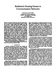
Fig. 1 – General REMPLI Architecture Using power lines for communication is not a new idea [1]. Using an already deployed infrastructure eases communication costs, not only for energy providers, but also for user applications, such as facility management, Internet access and “no-new-wires” area networks. Nonetheless, the peculiar physical layer of power-line for data communication introduces specific requirements, and the traditional communication technology must be revised to implement an efficient and reliable system [2]. One of the goals of the REMPLI (Real-time Energy Management over Power-Lines and Internet) project [3] is to implement an infrastructure for real-time communication (Figure 1), in order to remotely access monitoring and control equipment [2]. Within the power lines, a two-level hierarchical system is used (in REMPLI it encompasses the medium-voltage and low-voltage systems). This hierarchical structure implies the development of new protocols for end-to-end communication with timing and reliability requirements.
In the REMPLI architecture, the end-to-end application services must be provided over an already existing master-slave Medium Access Control (MAC) [4]. Since the underlying master-slave network only encompasses a single PLC network level, it is necessary to provide higher-level end-to-end communication services. Furthermore, due to the dynamics of power-line systems, different routing paths may exist from the source to the destination node. This paper presents the PLC protocol layer that provides these services and is structured as follows. Since power-line communication behaviour is reasonably common with ad-hoc/wireless networks, in the following section we briefly present some of the characteristics of these latter systems, identifying points of similarity and of difference. Then, in section 3, we give a brief presentation of the underlying master/slave network and the requirements of the services to be provided to applications. Afterwards, in section 4 we
present the architecture of the proposed Transport Layer, which is used for queuing and routing within the PLC system. Finally, sections 5 and 6 detail, respectively, the queue and the route management functionalities provided.
2. MANETs and other Wireless networks. Although comparing Mobile Ad-hoc Networks (MANETs) with Power-Line Communication (PLC) networks may look awkward, some of their main characteristics are similar. Unfortunately, these similarities are not adequate to use MANET solutions directly within the proposed transport layer. Considering MANETs, it is possible to immediately identify several of their key characteristics [5]: Dynamic topologies: Nodes are free to move arbitrarily; thus, the network topology - which is typically multihop - may change randomly and rapidly at unpredictable times, and may consist of both bidirectional and unidirectional links. - Bandwidth-constrained, variable capacity links: Wireless links will continue to have significantly lower capacity than their hardwired counterparts. In addition, the realized throughput of wireless communications - after accounting for the effects of multiple access, fading, noise, and interference conditions, etc. - is often much less than a radio's maximum transmission rate. - Energy-constrained operation: Some or all of the nodes in a MANET may rely on batteries or other exhaustible means for their energy. For these nodes, the most important system design criteria for optimization may be energy conservation. - Limited physical security: Mobile wireless networks are generally more prone to physical security threats than are fixed-cable nets. The increased possibility of eavesdropping, spoofing, and denial-of-service attacks should be carefully considered. Existing link security techniques are often applied within wireless networks to reduce security threats. As a benefit, the decentralized nature of network control in MANETs provides additional robustness against the single points of failure of more centralized approaches. Although PLC systems consist of fixed stations, the varying characteristics of the transmission medium produce a system where the network topology may indeed change randomly and in an unpredictable fashion either due to programmed operations (power network switching equipment) or to a variety of external factors (e.g. the electric noise from an elevator motor, user switching commands, etc) The used Network Layer [4] partially handles this “mobility” at each master network but it is the task of the upper layers to handle multimaster roaming of devices. Also, due to the long distances and large number of nodes involved, the
power-line communication system has constrained capacity and severe external interferences. Energy is not an issue for common power line communication systems, but radiated energy (e.g. radio waves) must be limited to avoid interference with household devices. This, combined with the fact that the medium is not protected in any way to avoid radio energy propagation, limits the maximum power that one may insert in the system. The direct drawback of this constraint is that there is a limited usable maximum distance for power line communications and complex physical layer algorithms must be in place to make the most of the available medium. Security can be a serious issue for power line communication systems, especially if they are used for applications that include billing and control of switching devices. In the REMPLI project the security layer will be handled at the application level and it is invisible to the transport system. From the point of view of the transport system there is, however, one big significant difference from typical MANETs: REMPLI is a two-level network, i.e. a network where most packets are forwarded by one and only one device until they reach the destination. This limits the usage of MANET protocols since they are inefficient in this scenario. For example: the presented system uses a route approach similar do Dynamic Source Routing (DSR) [6], however it is much more efficient in our system to find routes using the data link quality service of the Network Layer than to use route discovery when a route is not known to a node. Other typical MANET problems like loop avoidance [5] do not apply to our system since packets are only forwarded by Bridges. Furthermore, being a master/slave system we know a priori that slave to master data transfer requires a previous master to slave communication, being this concept not taken into account in any of the main MANET protocols. Another important difference is the request/response nature of the network. Traffic does not flow randomly on the presented network (like most MANETs), neither follows a source-sink paradigm (like sensor networks). Access Points will issue periodic bursts of packets to nodes in a considerably periodic way and expect a response (again a burst of packets) from the addressed nodes. Due to several application-specific issues (including legal and certification questions) it is not possible for the presented communication system to be an active part in these requests. For example, storing meter data locally at the bridges, although very interesting in computing terms, is forbidden due to the need of having this particular mechanism certified by each national power metering authorities. However the main applications themselves (servers and metering devices) have already passed these requirements and the task of the Transport System is to provide a transparent
communication channel between the higher-level applications. Nevertheless, when it comes to select one of the available routes and deciding which queue to serve next some of the work on fair queuing for wireless networks [7] is usable in the presented system, however it must be adapted to take into account the end-to-end costs and delays.
3. The REMPLI Network Layer Services 3.1. The Power Line Communication System Power line grids are typically divided in several voltage groups: higher voltage is used for power transportation over large distances, and lower voltages are used for power distribution on more limited areas. The REMPLI Project aims at the last two voltage-levels of this distribution grid. On the end side we have the final consumers. Between the medium and low voltage levels we have a transformer for voltage conversion (and power transmission) and a REMPLI Bridge for data forwarding purposes. On the entry side of the medium voltage network we have a REMPLI Access Point that interconnects the power line communication system and a broadband backbone. This data backbone is already available in most of these facilities. For the device to device communication the REMPLI system uses a time-division-multiplex Master/Slave communication protocol [4]. The majority of systems will use 3 or 4 time slot cycles and slots are assigned in every cycle to the available Masters (in a single Master system, all slots may be used by that Master). Since the Network Layer has an automatic repeater feature (where slaves may be used to forward requests to slaves far from the master) depending on the current medium data transmission characteristics this Master/Slave communication system may use 1 to 3 slots for unconfirmed requests and 2 to 6 slots for confirmed requests (if the automatic retry feature is enabled than this values may be multiplied by 2 or 3 for confirmed requests). This media adaptation procedure is handled automatically by the Network Layer. Requests are timeinterleaved by the Network Layer (i.e. request is sent in one cycle, response is received in a posterior cycle) and so it behaves like it has several independent communication channels in parallel. A representative setup would assign the first 2 time slots for one Master and the other 2 time slots for the other Master. The data payload of each slot is fixed and typical values for raw data payload (i.e. including the Network Layer own headers) are 64 and 128 bytes. As in many other applications, increasing the data length in the system decreases header overhead and increases the probability of an error (the encoding used is all-ornothing: if a bit cannot be decoded than the complete packet is discarded). Decreasing data length also
decreases the slot time and so the system can process more messages per period of time. The Network Layer also as other characteristics especially significant for the presented system: - Multicast and broadcast support (however due to the nature of the communication system multicasts and broadcasts can be “expensive” when it comes to used slots) - Automatic slave link management with authorization lists and reporting to higher layers of unique serial number and link quality - Reverse-channel (Slave to Master) Status service - Internal dispatcher including 2 priority queues at master and slave (high priority queue is completely served before low priority queue) 3.2. Services available to Applications From the point of view of applications that use the Transport Layer (Figure 2), each Access Point will have direct connection with several devices (Bridges and Nodes). AP
003
NODE
205
Transport Layer
APP: 1205
BRIDGE
BRIDGE
NODE
NODE
NODE
APP: 1102
APP: 1104
APP: 1201
APP: 1203
APP: 1205
102
Unique Serial Number
AP
001
104
201
203
205
Node Addr
Fig. 2 – Application’s view of the system In this document we use “Unique Serial Numbers” to identify each device on the text: i.e. “Node 203” means “Node with the Unique Serial Number 203”. In the example network of Figure 2, applications in Access Point 001 and Access Point 003 may issue requests to any of the network devices (Bridge 102, Bridge 104, Node 201, Node 203 and Node 205). The only difference is that delays and available bandwidth will vary for each Access Point – Device combination. Depending on the network topology each Access Points may have access to only a sub-set of nodes/bridges, but this is not the case in this example. From the applications point of view there are only two classes of devices in the network: “Access Points” and “Bridges/Nodes”. The main services that may be issued from the Access Point side are [2]: - Unicast Request with response - Unicast Request without response and from the Node/Bridge side: - Respond to Request - Send Alarm - Status Update The Unicast Request without Response service sends data to a particular node/bridge without confirmation of delivery. The Unicast Request with Response service
sends data to a particular node/bridge and demand the node/bridge a data response to the request. The node/bridge uses the Response to Request service to send this data. Only one response may be issued for each request. Both Unicast Requests have a priority field so applications may indicate what requests are more urgent than others. Access Points address nodes and bridges using a Node Address. Using configuration tools at the Access Points it is possible to change the Node Address of any bridge or node using the device’s Unique Serial Number. This mapping makes it possible to change a device on the network with minimum reconfiguration work. It is also possible to limit the universe of nodes and bridges that may connect to the network at the Network Layer level. The Send Alarm service is issued by a node/bridge and the data will be delivered to, at least, one of the available Access Points. The node/bridge may not preselect the destination of the Alarm message, and it will receive a confirmation of correct delivery. The Status Update service will update periodically the status information (typically 8 bytes) on the Access Points for each node/bridge. Since this is a poll service, if a node/bridge updates the status too fast some Access Points may miss some of the updates. Except for the Status Update service all the services may transmit large data blocks (up to 32MB) although time-critical applications will usually use very small data blocks (up to 100 bytes). 3.3. Example Network Layout In order to exemplify the network architecture, Figure 3 portrays the same network of Figure 2, but now showing the internal Network Layer network. AP 001 Level 1 Network Layer
AP 00
High Error Rate Link
1
5
BRIDGE APP: 1102 102
NODE 201
2
3
APP: 1201
4
BRIDGE APP: 1104 104
1
1
Unique Serial Number
2
2
Level 2 Network Layer
NL Addr 5
NODE 205
APP: 1205
Node Addr
1
APP: 1203
NODE 205
Applications
Config. App.
App. A
App. B
Application De/Mux
Transport Layer RCI Manager Queue Manager
Transport Route ManagerRoute
Queue Units
Tables
Network Layer Interface
Network Layer
Unit De/Mux
Master Unit Tx Queue:
Slave Unit Hi
Low
Only in Access Points and Bridges
Tx Queue:
Hi
Low
Only in Bridges and Nodes
Fig. 4 – REMPLI internal architecture In this example each network has two masters. Masters share the medium using a time-division multiplex scheme: considering a 4 slot system, one of the masters will use 2 slots and the other master will use the other 2 slots. Figure 3 also presents the active links between masters (top of link) and slaves (bottom of link). The numbers in each circle are the addresses used by the Network Layer (the first number identifies the unit in the Master Network Layer; the second number identifies the Slave in this particular network). For example Bridge 104 can be reached by AP 001 using address pair (1, 5) and can be reached by AP 003 using address pair (2, 4). On the opposite direction Bridge 104 will respond to AP 001 using address 1 and to AP 003 using address 3. These addresses are generated at run-time by the Network Layer and passed to the Transport Layer of each device after successful connection.
4. The Transport Layer Architecture
5
NODE 203
internal node functionality (i.e. can interact with a Access Points like a Node).
APP: 1205
Fig. 3 – Example network setup As in most locations where the Transport System will be used, this network has two physically separated networks: “Level 1 Network” and “Level 2 Network” (the system may also be used in single-level networks). The two networks are connected by “Bridge” devices. Bridges besides connecting the two network levels have
The REMPLI Transport Layer is implemented using four inter-connected modules as presented in Figure 4. The RCI Manager module distributes messages between the Queue Manager / Transport Route Manager and the Applications themselves using an available interface: the REMPLI Communication Interface (RCI). The Network Layer Interface module distributes messages between the Queue Manager / Transport Route Manager and the Network Layer doing parameter conversion when needed.
The Queue Manager module manages all the packet data information. Tasks like queue generation, disposal, fragmentation and transport system header processing are done at this module. This module also multiplexes requests from the Applications and the Transport Route Manager to the Network Layer Interface data transmission services. The Transport Route Manager module handles not only the scheduling tasks but also all the tasks that need internal Transport Layer communication. When a new data request is queued in the Queue Manager it is the task of the Transport Route Manager to provide the appropriate route (or to reject the request due to unavailable path). The Transport Route Manager will also instruct the Queue Manager when each queue should be served. 4.1. Synchronization with the Network Layer The Transport Layer keeps track of the Network Layer timing using an asynchronous model. The scheduling process at the Transport Route Manager is triggered by the following events: • A packet is read from the Network Layer internal queues. This generates a message to the Transport Layer. The Transport Route Manager will try to find an available Queue Manager queue to fill the vacant Network Layer queue. • A new request is received from the Applications and there is a vacant Network Layer queue space. • A Network Layer request is completed or aborted resulting in a change on the Queue Manager internal queue states. Since the Network Layer is a slotted system we have a quantifiable maximum number of scheduling events that we may have in a predetermined period of time. This solution has de advantage of small complexity and guaranteed data availability to the Network Layer albeit with sub-optimal transmission delays.
5. The Queue Manager The main task of the Queue Manager is to store temporary data before it is sent to the network or to the applications. Other tasks include: - Pair requests and responses using the Transport System header data and stored information. - Provide communication service to the Transport Route Manager own messages - Fragmentation - Bridge forwarding 5.1. Sending and receiving data When the Queue Manager receives a new request from the applications it will store the data of the request and inform the Transport Route Manager of the new queue. The Transport Route Manager will reply first by sending route information or a “discard queue”
command. After this the Transport Route Manager will instruct the Queue Manager to send to the network each fragment in the queue and the Queue Manager will keep the Transport Route Manager informed on the data transmission process. When all fragments are processed the queue information is deleted at both the Queue Manager and the Transport Route Manager. On reception from the network the Queue Manager rebuilds the data information if needed and delivers the final data block with additional service information either to the application or the Transport Route Manager. 5.2. Fragmentation Since the Network Layer uses small fixed-length frames the Transport System must fragment the application requests in several frames and reassemble them at the destination. We may have several parallel transactions and so the Queue Manager must identify each fragment with a packet id. For correct-order delivery (the Network Layer may deliver fragments outof-order) the Queue Manager must also include fragment order information. Both these fields have been reduced to a minimum to limit the impact of the Transport System header on the data payload. The Queue Manager also supports different sized frames for the 2 Network Layer levels: Bridges will keep temporary buffers for the en-route packets in order to optimize this fragment-size conversion. Due to the technology used the raw data length of the Network Layer is always a power of 2, but since this data length includes the Network Layer own headers the bridges may not do simple division or union of fragments.
6. The Transport Route Manager The Transport Route Manager module is the main responsible for management of the system. In addition to the main run-time route determination and scheduling of fragments the Transport Route Manager also takes care of the system start-up (including remote device plugand-play operation) and automatic route discovery and route status dissemination. AP 001
AP 003
Level 1 Network Layer
Fig. 5 – System Startup 6.1. System Startup When the system is powered up, only Access Points start their Master Network Layers (Figure 5). The rest of the devices on the network have their Slave unit’s onhold waiting to receive physical layer information from the Master. Bridge devices disable the Master Network
Layer unit, so there is no activity on the Level 2 Network. As each slave unit receives physical layer information (slot time, encoding information, etc) it will synchronize with the respective network. In the meanwhile the Configuration Applications in the Access Points will have loaded Slave Control Lists to the respecting Master and connection requests will be issued periodically using specific Unique Serial Numbers. When a Slave responds to one of this connection requests the Master/Slave addresses will be generated by the Network Layer. The Transport Route Managers at the master and slave side will receive messages from the Network Layer for every connection event (Figure 6). AP 001 Level 1 Network Layer
AP 003
AP 001
BRIDGE 102
BRIDGE 104
NODE 203 APP: 1203
1
Fig. 8 – Two possible routes
2
BRIDGE 102
BRIDGE 104
Fig. 6 – Bridge 102 connected For each new AP-Bridge connection, the Transport Route Manager at both devices will exchange basic configuration data and the Node Address will be assigned to the Bridge. After this the Transport Route Manager will enable communication between the AP and Node Configuration Applications to set the rest of the Bridge parameters including the Master unit start-up (Figure 7). This process will go on for all the devices in the system and eventually they will all be interconnected. AP 001 Level 1 Network Layer
For simplicity the REMPLY system routes all fragments of a particular request (and response, if applicable) using the same path. This simplification means that routing decisions are only taken on the Access Point and once per request/response. It also means that path information must be sent in the packets (see next section).
AP 003 1
2
BRIDGE APP: 1102 102
BRIDGE 104
Level 2 Network Layer
Fig. 7 – Bridge 102 Master Unit activated 6.2. Bi-level Routing Concept The two main services used by AP Applications will be a Request/Response service and a Request without Response service. The main topic with these two services is to decide which route should be used to send the request from the AP to the Node using the available Bridges. In the example network a request from AP 001 to Node 203 may be routed either using Bridge 102 or Bridge 104 (Figure 8).
The Transport Route Manager keeps track of possible paths creating route entries for every new Master/Slave pairing in the network. When a Node connects to a Bridge the Bridge will add an entry to its internal “connected node” list. This list has the Node Unique Serial Number and the Network Layer address pair of the node. This data is then transferred to the Access Point’s Transport Route Manager by an internal Transport system service. The Transport Route Manager at the Access Point side will then save this information together with the Bridge Network Layer addresses. 6.3. Routing data reduction using look-up tables The Network Layer packets have a very limited length (a typical value would be 64 bytes, including Network Layer header). If we would pass complete addresses in every packet this would result in unacceptable overhead. The Transport Route Manager uses conversion tables with small-length indexes at the Bridges to reduce the amount of information dramatically. Assuming that we have a maximum of 1000 Nodes connected at the same time to a Bridge we can use 10 bits for this index. When a Node connects to a Bridge using the Network Layer the Bridge Transport Route Manager will store a 10 bit index, and the 2 Node Network Layer addresses. This index will then be sent to the Access Point and will be used by the later to route packets through the Bridge to the Node. For the reverse direction the procedure is similar: for every Access Point that the Bridge is connected to, the Bridge stores a 10 bit index and the Access Point Network Layer address. When a packet is forwarded from the Access Point, the Bridge will add the Access Point index on the forwarded packet. This index together with the Bridge Network Layer address identifies
unequivocally the originating Access Point at the Node side. 6.4. Routing decision parameters The route selection process is done on a request by request basis. The Access Point scheduler uses the Probable Cost of each route to make the routing decision (Figure 9). To estimate the cost of each route (one way) the transport system uses: - AP/Bridge Link quality - Bridge/Node Link quality - Bridge queue status The first information is available directly at the Access Point’s Transport Route Manager but it is also, by definition, an estimate: the Link Quality indicates the previous link quality; due to the changing characteristics of the data communication medium this value may change unexpectedly and the scheduling algorithm must have this effect into account. Bridge/Node Link quality is data relayed from the Bridge to the Access Point by the Transport Route Manager. It has the same unpredictability problem of the previous plus the significant additional delay due to Bridge to Access Point communication. Bridge queue status is also data relayed from the Bridge to the Access Point by the Transport Route Manager. Here the unpredictability is also a factor since other Access Points may influence these queues.
confirmed requests (see Figure 10). In this example network we have 2 masters in each Network Layer each using 2 of the 4 available time slots. Non confirmed
Confirmed
Non confirmed - lowQ link
Confirmed - lowQ link
Fig. 10 – Timing examples for Network Layer requests The cost and delay for unconfirmed requests can be calculated by:
c1,102, 203 = c1,102 + c102, 203
d1,102, 203 = d1,102 + d102, 203 + dmq102 where ca,b are the link costs, da,b the link delays and dmqn is the queue delay for the master queue of the Bridge. Setting the queue delay to zero we have the following results:
c1,102, 203 = 1 + 1 =2
d1,102, 203 = 1 + 1 + 0 =2 c1,104, 203 = 2 + 2 =4
AP 001
d1,104, 203 = 5 + 5 + 0 = 10 BRIDGE 102
BRIDGE 104
NODE 203 APP: 1203
Fig. 9 – Route cost/delay calculation For a request/response service we should also include the queuing delay on the Bridge in the reverse direction and use a correction factor for the transport delays due to the extra overhead needed to gather the information on the slave. The exact scheduling algorithm is out of the scope of this document. But the Transport Route Manager has all the remote information so the internal scheduler it can make the best possible choice for a given scenario. As an example, we will assign “good” links a cost and delay of 1 for unconfirmed requests and a cost of 2 and delay of 5 for confirmed requests; and to “bad” links (AP 001 ÅÆ Bridge 104) a cost of 2 and delay of 5 for unconfirmed requests and a cost of 4 and delay of 13 for
The cost and delay results may be used by the scheduling system with two slightly different objectives: Cost can be used to estimate the maximum load that we can put in the network without additional queuing delays. For the present example we can spend at most 2 cost units every 4 time slots. Delay can be used not only for the maximum load but also to guarantee that deadlines are met. A very simple algorithm (and very unfair) can cleanly select the lowest cost or delay path. In the presented scheme both options would result in the selection of path (1, 102, 203) for an unloaded network.
7. Conclusions Due to master-slave behaviour of Power-Line Communication (PLC) Medium Access Control and the inherent dynamic topology of power-line networks, in order to provide application end-to-end communication, it is necessary to provide a queuing and routing mechanism as well as other accessory services. This paper presented the proposed architecture and main functionalities of the mid-level protocol layer, part of
which is being implemented for this purpose within a two-level PLC architecture. The paper identified some of the similarities with MANETs and wireless networks, which allowed us to clearly identify the main requirements for this system, and specify the transport system architecture. Then, we described in more detail the routing and queuing procedures which are being used. This system is currently being implemented in a discrete-event simulation environment, and afterwards will be deployed in the actual devices. References [1]
[2]
M. Lobashov, G. Pratl, T. Sauter, “Implications of Power-line Communication on Distributed Data Acquisition and Control System”, IEEE Conference on Emerging Technologies and Factory Automation, Lisbon, Portugal, 2003. A. Treytl, T. Sauter, G. Bumiller, “Real-time Energy Management over Power-lines and Internet”, Symposium
[3] [4]
[5]
[6]
[7]
of Power-Line Communication and its Applications, Zaragoza, Spain, 2004. Real-time Energy Management over Power-Lines and Internet, NNE5-2001-00825, http://www.rempli.org G. Bumiller, M. Sebeck, “Complete Power-Line Narrow Band System for Urban-Wide Communication”, Symposium of Power-Line Communication and its Applications, Malmö, Sweden, 2001. S. Corson, J. Macker, “MANET: Routing Protocol Performance Issues and Evaluation considerations”, RFC 2501, IETF Network Working Group, January 1999. http://www.ietf.org/rfc/rfc2501.txt D.B. Johnson, D.A. Maltz, Y-C. Hu, “The Dynamic Source Routing Protocol for Mobile Ad Hoc Networks (DSR)”, Internet Draft, IETF MANET Working Group, April 2003. http://www-2.cs.cmu.edu/dmaltz/internetdrafts/draft-ietf-manetdsr-09.txt V. Bharghavan, S. Lu, T. Nandagopal, “Fair Queueing in Wireless Networks: Issues and Approaches”, IEEE Personal Communications Magazine, Feb 1999