Robotics Applications ... systems and their accelerating development cycles, it is important ... CORBA [12], was not available for the real-time Linux. Fig. 1.
RACK – A Construction Framework for Real-Time Robotics Applications Sebastian Smolorz, Bernardo Wagner Institute for Systems Engineering Real-Time Systems Group University of Hannover, Germany {smolorz, wagner}@rts.uni-hannover.de
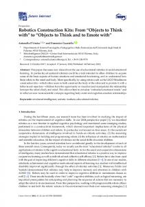
Abstract—Because of the growing complexity of automation systems and their accelerating development cycles, it is important to facilitate and optimise the development of related software. The Robotics Application Construction Kit (RACK) aims at providing a framework for building robotics applications, specifically for autonomous mobile service robots. It supports the development of hard real-time as well as non-real-time components. RACK defines component classes for sensor and actuator drivers like robot chassis, odometry, laser scanner, or camera and for data processing components like laser scan post-processor, navigator, or localisation module. Furthermore, it specifies the interfaces between those classes. This paper explains the design as well as the implementation of RACK and describes an autonomous service robot which uses this framework. Index Terms—autonomous service robots, real-time robotics framework, networked multi-robot system, Xenomai.
I. I NTRODUCTION A complete service robot is a complex system that is made up of different sensor inputs, software working on sensor data and actuators for driving or manipulating the environment. Autonomous service robots can guide through museums [1], provide household services, or help to optimise industrial logistic processes. A successful example is the autonomous fork lift truck which resulted from a cooperation between the RTS and the Still GmbH [21]. To control such robots, computations for sensor data fusion, perception and navigation are required. In addition, deterministic processing on distributed controllers is often necessary which leads to the need of real-time communication. A compact framework adapted to those requirements was developed at our institute to enable research on autonomous service robot systems. By means of RACK controls on single computer platforms as well as distributed controls can be realised. RACK contains elementary functions that are needed to monitor and control autonomous robots. Several approaches exist which cover robotic-specific software frameworks. The Open Source Robot Operating System OROCOS [11] was designed to satisfy requirements of a wide range of robotics and control software. The framework supports abilities and services concerning control engineering but is yet lacking suited interfaces and components which can be used for mobile service robots. RT-CORBA [8], a real-time extension of the middleware CORBA [12], was not available for the real-time Linux
Fig. 1.
RACK architecture
extension Xenomai [16] which is used in our service robots. Moreover, we considered RT-CORBA as too extensive for our application scenarios and therefore too hard for beginners to get acquainted with. There are a number of further free robot software projects available, e.g. Dave’s Robotic Operating System [13], the Player/Stage project [14], or the Mobile and Autonomous Robotics Integration Environment (MARIE) [15], but none of them fulfilled our requirements of distributed hard real-time processing. In the following section, the design of the generic RACK framework is described. Section III gives an overview on the available hardware abstractions and algorithm classes specific to service robots as well as on their interfaces. Aspects of component implementation as well as RACK’s requirements and internal realisation is presented in section IV. An exemplary robot system based on RACK is described in Section V. This paper concludes with a summary and an outlook on future enhancements of RACK. II. F RAMEWORK A. Component Based Architecture Autonomous robot systems can consist of serveral subsystems. Every subsystem runs on its own host, and different hosts can be integrated in a mobile robot. The subsystems are made up of RACK components. Any component is strictly encapsulated and cannot access the memory of others directly. RACK is a middleware, i.e. a mediation layer between RACK components on the one side and low level device drivers, other abstraction layers, and operating system services on the other side (see Fig. 1). Definite interfaces for device drivers like CAN and serial ports are provided in addition to
Fig. 3.
Fig. 2.
Distributed Robotic System
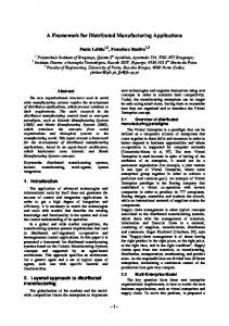
task services, communication and synchronisation mechanisms like mutexes. The communication between components only occurs with the messaging service TiMS (see Section IV-A), which is part of RACK. Figure 2 shows a simplified example of a distributed robot system supported by RACK. B. Inter-Component Communication RACK provides a consistent mechanism to realise communication between RACK components exclusively using mailboxes. A primary mailbox is used in every component for receiving incoming commands encapsulated in messages (see II-B1). Further mailboxes can be created on demand for obtaining data from other components or to further component-individual requirements. The framework defines message types that permit communication between components. These message types are used to send commands and replies according to the remote procedure calling (RPC) scheme as well as one-way data messages. Data exchange is provided either via a polling model by issuing a request and awaiting the data as the reply. Alternatively, a publish/subscribe model is maintained which allows components to register on data streams other components generate. By convention components are not allowed to send data without being explicitly asked by the receiving module. Components can be distributed on different computer architectures, therefore incoming messages have to be converted on reception into the local byte order format in case the sender used a different one. 1) Messages: A consistent format is given to all messages, consisting of a 16 byte long header and a variable payload. The header contains routing information (source and destination address), the message length, its type, the priority on the transmission channel and in the destination mailbox, a sequence number and flags encoding the message byte order. Mailbox addresses are created according to their names as described in Section II-B2. A certain range of message types is used by RACK internally to realise core services (see e.g. II-F1). Therefore, an offset is given for customisable types. Commands that are
RACK Mailbox Address
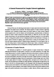
sent to components are encoded as positive types, replies as negative ones. 2) Naming: To access components globally, unique component identifiers are necessary. These identifiers correspond to the primary mailbox addresses of the components. A mailbox address or a component identifier respectively consists of four ID fields each of which typically has a length of one byte: the system ID, instance ID, class ID, and the local ID. However, when designing a robot system, the size of the fields can be set individually. Fig. 3 shows the segmentation of the mailbox addresses we use in our robotic systems. By means of the system ID, several robot systems can be distinguished. The class ID defines the generic component class as further refined in Section III-A). In order to use multiple components of the same class in a robot system, every component is given an instance ID. The local ID is used to address the different mailboxes in a component, starting with 0 for the command mailbox. 3) Routing: The distribution of messages to remote systems is realised via hierarchical routing. Every computer platform used by RACK has a message router which registers the mailboxes of all local components. To send messages to other platforms or systems, the address of a router in the next level has to be known. Every router informs its super router about the presence of all known component mailboxes. Therefore the top-level router registers all available mailboxes of any attached robotic system. Intra-system routing can be performed with explicitly giving the system ID. In Fig. 4 a hierarchical routing example is shown. Following router types exist: • Router - A subsystem router which sends messages with an unknown destination addresses to the given higher level router. • System Router - Highest-level router of a robotic system. All mailbox addresses of the local system are registered. A system router can receive and forward messages from related subsystem routers as well as foreign system routers. • Top Level Router - This router registers the mailboxes of all used robotic systems. If the top level router does not know the destination address, the message will be discarded. C. Execution Model In a generic component the command task blocks until a message is received and executes the proxy handlers corresponding to the proxy command. After the handler is finished the task waits for the next command. A component creating or manipulating data has an additional data task to request and receive data from other
Fig. 5. Fig. 4.
Rack Module
Message Routing
getStatus() - This proxy handler returns the actual module state (ENABLED, DISABLED or ERROR). These generic proxy handlers are also part of RACK. The handler On() and Off() can be overwritten e.g. to request countinous data from other components. Proxy handlers are called by the command task, thus all handlers must not block in an unbounded manner. •
components, to work on data and to save it into a specific data buffer. Within components additional tasks with special jobs can be realised optionally (e.g. a watchdog). It is possible to start tasks with a higher priority. In opposition to the software framework [2] that was used before at the RTS institute the task priority is not hard coded into the class ID. Thus data streams including different components can be realised by setting the same priority. D. Generic Module Interfaces Components have to provide two different application interfaces. One interface is used directly by the middleware RACK to start, to initialise and to clean up the component. The second interface is needed to give components the possibility to communicate among themselves. Other components are able to call this interface by means of proxies. Thus proxy handlers are necessary to execute proxy commands. Fig. 5 shows all tasks and functions of a generic module. 1) RACK Interface: RACK uses the following functions inside a generic module: • init() - While loading a component this function is executed by main() to allocate memory for all data structures, to open devices and to do other initialization tasks which must not occur in real-time context. • command() - This function is called by the command task after a new message (RPC) is received and executes proxy handlers according to their commands. • cleanup() - While unloading a component cleanup() is called by the signal handler to clean up the module. Only the main() function has to be implemented inside a new component. All other generic functions are already part of RACK but they can be overwritten to realise specific needs. 2) Proxy Interface: The command task executes these handlers according to the received proxy commands: • on() - If a component is activated by another one this proxy handler prepares the module to run in real-time context. • off() - When turning off a component the command task executes this handler to reverse all steps done in the on() function.
E. Data Module Interfaces Modules store produced data as well as the corresponding timestamps into their data buffer. The number of data sets and consequently the timestamp history depends on the used buffer size. Other components can request data close to a given timestamp (Polling) as well as a continuous data stream. Data with specific timestamps is needed for sensor data fusion. Opposite to the generic module a data module has further interface functions described in this section. 1) RACK Interface: The following function has to be implemented inside a new data module in addition to the generic module interface: • loop() - In a negotiated periodic cycle the data task executes this function to get needed data from drivers or other components. The data task has to take place to save the created or manipulated data into a specific data buffer. 2) Proxy Interface: A component which creates or manipulates data has to provide additional proxy handlers to realise the polling model as well as the publish/subscribe model. These handlers are part of RACK and cannot be overwritten: • getData() - To facilitate the polling model this proxy handler is provided. Other components can request data close to a needed timestamp. The data task looks inside the data buffer for suitable data and sends it to the waiting recipient (synchronous). • getContData() - Using getContData() receiving components ask for a continuous data stream. This handler adds the recipient into the listener list. A negotiation of the period time occurs by receiving the desired period time and sending a suggesting time supported by this component. As soon as data exists and the time condition is fulfilled the data task sends produced data to the recipient (asynchronous).
4) Argument Interface: RACK provides an interface to transfer specific arguments and parameters into the components. For this purpose a data structure is given to define these arguments and to save their values. While starting a component the middleware analyses all given arguments and parameters and writes corresponding values into the data structure. Components can access these values directly. G. Graphical User Interface
Fig. 6.
Rack Data Module
stopContData() - To close a data stream this proxy function is called by the receiving component, thereby the recipient is removed out of the listener list. Fig. 6 shows all tasks and functions of a data module. In Tab. I all generic and data proxy handlers are listed. •
TABLE I G ENERIC AND DATA P ROXY H ANDLERS Function on() off() getStatus() getData() getContData() stopContData()
Module generic generic generic data data data
F. Additional Services 1) Logging Service: While developing distributed systems one practical problem is to keep track of all information and debugging messages displayed on several screens or showed on remote consoles by diverse components. Thus a real-time safe logging service is needed collecting all information and debugging messages to show them on a central user interface. The quantity of information sent by this service has to be set using information levels. Corresponding components can be analysed, errors may be detected more simple and corrected systematically. All information can be saved on a data medium to analyse them later on. 2) Context Switch Detection: It is important to make sure that all components are running in a predefined state. Timecritical jobs have to run continuously in real-time context. An undesirable context switch must be detected and notified. RACK is able to detect these context switches and to enforce a back-tracing (see II-F3) to find and correct such unobvious bugs. The detection is also helpful to validate unknown libraries concerning real-time abilities. 3) Back-tracing: After the appearance of unexpected events or errors an internal back-tracing service is engaged in order to assist the developer to find the cause of the error more quickly. RACK shows the stack of the last called functions on the console to analyse errors like segmentation faults and context switches.
The Graphical User Interface (GUI) supports the development of robotic systems by providing the following capabilities: • Diagnostic analysis of components • Configuration of components • Displaying system information (described in II-F1) The other purpose of the GUI is a user-friendly handling of a complex autonomous robot system: • Operating different robotic systems • Setting of navigation waypoints. • Controlling a chassis by using a software joystick III. RACK C OMPONENTS A RACK component is the smallest executable unit of our autonomous service robot systems. Due to the encapsulation the components can be substituted by others without changing the complete system. Furthermore it is possible to implement the components in different programming languages and to run these modules on distributed systems. The partitioning of these components into classes and the realisation of the communication between components by means of proxies will be described in this chapter. A. RACK Classes Component classes can represent abstract hardware classes like sensors and actuators as well as data processing modules. For example, driver components for laser scanners produced by manufacturers like Sick [22] or Ibeo [23] are assigned to the abstract class Ladar. The communication between components of different classes occurs exclusively over proxies described in the next section. In Tab. II some of the currently defined classes are displayed. B. RACK Proxies Class specific definitions like message types, data structures (including their parsing functions) and supported proxy functions are defined in a proxy specific to every RACK component class, in addition to the generic and data proxies described in section II-D2 and II-E2. Due to the abstract classes only one proxy is needed to access all similar components within a class. Some classes have to extend the generic proxy API, e.g. the chassis proxy: In order to send commands to the chassis component and fulfil special navigation jobs a pilot has to be set beforehand via the GUI. Therefore the chassis proxy function setActivePilot() is
TABLE II C OMPONENT C LASSES Class Camera Chassis GPS Gyro Joystick Ladar Odometry ServoDrive Path Pilot Position Scan2D Scan3D ObjectRecognition
Type Driver Driver Driver Driver Driver Driver Driver Driver Navigation Navigation Navigation Perception Perception Perception
provided as well as the according data structure and its parsing function. While using proxy functions received data is converted into the local data type automatically. IV. I MPLEMENTATION At our institute we work with embedded industrial PCs named Scalable Processing Boxes (SPB) [9], (see Fig. 7). They are equipped with x86 processors and PC/104 extension boards and include CAN interfaces and fast serial extension cards. The speed of the single and dual-core processors ranges from 266 MHz to 2.2 GHz. The operating system and the application software resides on standard CF-cards. We use a Linux operating system with the real-time extension Xenomai [16]. By means of Xenomai all real-time RACK components are able to execute in user space while also attaching to external libraries like libraw1394 (Firewire) [19] or opencv [20]. Low level kernel space drivers can be accessed by using the Real-Time Driver Model API and conforming drivers. Such drivers attach e.g. to CAN buses or serial ports. TiMS uses RTnet [3] for sending real-time messages over Ethernet. RACK supports the component development via a C++ class library. The messaging service TiMS, which is working in kernelspace (see IV-A), was realised in C. A Java package and GUI framework is provided for implementing user interfaces, including joysticks, or off-loading or prototyping noncritical components. A. Messaging Service TiMS The Tiny Messaging System (TiMS) was developed at our institute as part of RACK. TiMS consists of a kernel module and a userspace library. The core functions of TiMS and the routing over RTnet as well as over TCP/IP are implemented inside the kernel module. To use the messaging service by userspace components a library is given to define mailboxes and to provide corresponding functions. A component can choose to receive messages in three different modes: • blocking without giving a timeout (e.g. peek) • blocking only a certain amount of time (e.g. peekTimed)
Fig. 7.
Scalable Processing Box
non-blocking (e.g. peekIf) which means returning immediately in all cases The TiMS library supports two options to get messages: Small messages are copied during a receive() call into a data buffer inside the recipient. The message area inside the mailbox is freed immediately. If a big message is received the copy process may be very long and resources are unnecessarily blocked. In this case the memory area of the message can be locked by peek(), then the receiving task is able to work directly in this memory area. If all work is done, the area is unlocked with the peek end() function. TiMS gets all messages from RACK and sends them to the mailbox of the destination component using the TCP/IP stack (non-real-time) or RTnet (real-time). If the destination mailbox is located on the same host TiMS copies the message directly into a free mailbox data buffer and wakes up the waiting task of the corresponding component. Figure 8 shows the data flow. To route messages in a deterministic way a wired ethernet connection between the hosts has to exist. Messages to the user interface are transmitted by the normal linux TCP/IP stack. Therefore TiMS has an internal router to forward all messages which are not addressed to the local system to a router in a higher level (see II-B3). •
B. Components RACK components are independent applications that can be executed individually. Components are realised using the programming languages C++ and Java. All interface functions described in II-D are implemented as virtual functions in the class Module. Among the implementation of the main() function only an overwriting of the virtual functions is needed to realise the module. Following a source code of a simple module is shown. class SimpleModule : Module { moduleInit() { Module::init(); allocate_resources(); } moduleCleanup() { free_resources(); Module::cleanup(); }
Fig. 8.
Realisation of inter-component communication
moduleOn() { init_something(); Module::moduleOn(); } main() { simple = new SimpleModule(); simple->moduleInit(); simple->run(); return 0; } };
Fig. 9.
Graphical User Interface
moduleOff() { DataModule::moduleOff(); ladar->stopContData(ladarMbx); ladar->Off(); }
The class DataModule is derived from the class Module and extends the class with the functions explained in Section II-E. Inside init() memory for the data buffer is allocated and in the cleanup() function it is freed again. For instance a Scan2D module is derived from the class DataModule. The source code of this module is described below.
moduleLoop() { buffer = get_local_buffer(); ladarData = ladarMbx.recv(); driverData = get_data_from_sensor(); *buffer = calculate_data(ladarData, driverData); put_local_buffer(); } };
class Scan2dModule : DataModule { LadarProxy ladar; RackMailbox ladarMbx;
C. Graphical User Interface
moduleInit() { DataModule::Init(); createMailbox(ladarMbx); ladar = new LadarProxy(); open_sensor_driver(); } moduleCleanup() { close_sensor_driver(); delete ladar; ladarMbx.destroy(); DataModule::Cleanup(); } // handle self-defined proxy commands moduleCommand() { if (recv_command == my_command) { handle_command(); } else { // handle data proxy commands DataModule::moduleCommand(recv_command); } } moduleOn() { ladar->On(); ladar->getContData(ladarMbx); DataModule::moduleOn(); }
The GUI is implemented in Java and is able to control all components of different robotic systems. All started components are detected and shown on the interface (see fig. 9). They can be enabled as well as disabled. Data of components is requested periodically with a lower priority than critical jobs and is displayed on the GUI in separate frames. Every RACK class provides a GUI extension to indicate its own data. Inside the interface the logging service (see II-F1) shows all information in the message frame. D. Information Service To collect and display all information of the distributed components the generic distributed output system (GDOS) is used. It sends all messages in non-real-time context and with the lowest priority to the central user interface used by the system operator. The service shows the information and debugging messages of all distributed components in the GUI sequentially and converts all mailbox addresses into readable names (0x00012000 ⇒ Ladar[20]). The displayed information are coloured according to the information level. Thus important messages can be noticed at once. The level can be set dynamically by the GUI to keep transmission bandwidth free. There are five levels implemented: print, warning, error,
debug info and debug detail. All information messages can be saved on a medium to analyse them later. V. E XEMPLARY ROBOT S YSTEM In this section one of our autonomous robot system Dora which uses RACK is described. The outdoor robot has a length of 230 cm and a weight of 350 kg (see Fig. 10). This robot navigates autonomously with its maximum speed of 4 m/s. Dora is equipped with a number of components including chassis control, 2D ladar range sensors, GPS, gyro, 3D laser range scanner, pilots for navigation, path finder and localisation modules. A part of the used components is listed in Tab. III. Fig. 10.
TABLE III C OMPONENTS OF D ORA Component ChassisRobucar OdometryChassis Position PilotPath LadarSickLms200 GPS Gyro Scan2D PathRDDF MonteCarloLocalisation
period (Hz) 20 20 20 20 75 0.5 10 75 20 1
priority 40 40 40 40 30 30 30 30 20 20
The data of the laser scanner is requested by the Scan2D component to make 2D laser scans. These 2D laser scans are needed by a module which uses the Monte Carlo localisation [7] as well as the PilotPath module to calculate the actual position and to detect obstacles in the cruising range. The pilot module also gets data from the Path component which creates splines by means of given waypoints and sends move commands to the ChassisRobucar [24] module of Dora. The Monte Carlo localisation component needs a map of all static obstacles in the navigation area to ensure a precise position. The given priority of the running components depends on the needed response time. The detection of obstacles in the cruising range have to occur as soon as possible. Thus a component which have to react very quickly has a high priority. Components that are planning new paths to the destination points have a lower priority. In Fig. 11 the data flow is shown as well as the used period and the given priority of the RACK components running on Dora. VI. S UMMARY AND O UTLOOK We have realised the framework RACK that facilitates and optimises the development of distributed autonomous service robots. It includes abstract interfaces to typical robot sensors and actuators as well as to generic data processing components. By supporting the development of both hard real-time and non-real-time components, a wide range of robotic tasks are covered. Inter-component communication is handled by the transparent messaging service TiMS, which is able to fulfil both hard timing constraints and throughput requirements.
Outdoor Robot Dora
Within the scope of research projects, several robot components were developed or ported from the previous framework over RACK. A significant number of them are now publicly available as open source software. Future plans for enhancements of RACK include: • Improved non-real-time support - In order to ease the integration of complex nondeterministic algorithms, components will be executable under non-real-time environments as well. This will include TiMS support for standard Linux systems. • Strong access control - An ongoing research project gives attention to security issues of the messaging service TiMS [4], [6]. The aim is to confine less critical RACK components which may include malicious code by controlling the admissible message types, their priorities, and the used bandwidth, similar to the proposed protection of RTnet [5]. • Message Compression - As certain sensor data currently contain a significant redundancy, simple but fast message compression shall be included in TiMS. This will help to further reduces bandwidth requirements, specifically over wireless links. • Driver API - A low level driver interface to use real-time communication over the Universal Serial Bus (USB) [10] shall be provided. • Configuration Tool - To ease the configuration of robotic systems, which includes the distribution and parametrisation of components as well as the assignment of communication resources, graphical tool support based on Eclipse is planned. RACK is free software available under the GNU Lesser General Public License (LGPL). Moreover, several of its components are based on external open source libraries. The project aims both at fostering the development of further open source components and the reuse of available free solutions. At the same time it also allows to build proprietary projects on top of it. For downloads and further information, visit http://developer.berlios.de/projects/rack
Fig. 11.
Data flow and Prioritisation
R EFERENCES [1] S. Thrun, M. Beetz, et al., Probabilistic Algorithms and the Interactive Museum Tour-Guide Robot, International Journal of Robotics Research, 19(11):972999, 2000. [2] Wulf, O.; Kiszka, J.; Wagner, B., A Compact Software Framework for Distributed Real-Time Computing, 5th Real-Time Linux Workshop, Valencia, Spain, 2003. [3] Kiszka, J.; Wagner, B.; Zhang, Y.; Broenink, J., RTnet – A Flexible Hard Real-Time Networking Framework, 10th IEEE International Conference on Emerging Technologies and Factory Automation, Catania, Italy, 1922 September 2005, http://www.rtnet.org. [4] Kiszka, J. and Wagner, B., Domain and Type Enforcement for Real-Time Operating Systems, 9th IEEE International Conference on Emerging Technologies and Factory Automation, Lisbon, Portugal, 16-19 September 2003. [5] Kiszka, J. and Wagner, B., Securing Software-Based Hard Real-Time Ethernet, 2nd IEEE International Conference on Industrial Informatics, 24-26 June 2004, Berlin, Germany. [6] Kiszka, J. and Wagner, B., Modeling Security Risks in Real-Time Operating Systems, 5th IEEE International Conference on Industrial Informatics (INDIN 2007), July 23-27, 2007, Vienna. [7] F. Dellaert, D. Fox, W. Burgard, and S. Thrun, Monte Carlo Localization for Mobile Robots, IEEE International Conference on Robotics and Automation (ICRA99), May, 1999. [8] Douglas C. Schmidt, Fred Kuhns, An Overview of the Real-time CORBA Specification, IEEE computer special issue on Object-Oriented Real-time Distributed Computing, 2000 [9] P. Hohmann, U. Gerecke, B. Wagner, A Scalable Processing Box for Systems Engineering Teaching with Robotics, International Conference on Systems Engineering, Coventry, UK, 2003. [10] J. Langenberg, Analyse und Implementierung einer echtzeitf¨ahigen USBKommunikation unter Linux/RTAI am Beispiel einer 3D-Range-Kamera, diploma thesis, University of Hannover, Institute for Systems Engineering, Real-Time Systems Group, 2005. [11] OROCOS, Open Robot Control Software, 2009, http://www.orocos.org. [12] Object Management Group, Common Object Request Broker Architecture (CORBA) Specification, Version 3.1, 2008, http://www.omg.org. [13] David Austin, Dave’s Robotic Operating System, 2007, http://www.dros.org. [14] The Player/Stage Project, 2008, http://playerstage.sourceforge.net. [15] Mobile and Autonomous Robotics Integration Environment, 2009, http://marie.sourceforge.net/index.html. [16] Philippe Gerum, Xenomai: Real-time framework for Linux, 2009, http://www.xenomai.org. [17] P. Mantegazza, E. Bianchi, et al., RTAI: Real-Time Application Interface, Linux Journal, 2000, http://www.rtai.org. [18] Kernel.Org Organization, Inc, The Linux Kernel Archives, 2009, http://www.kernel.org. [19] IEEE 1394 userspace library, http://sourceforge.net/projects/libraw1394. [20] Open Source Computer Vision Library, http://sourceforge.net/projects/opencv/.
[21] D. Lecking, O. Wulf, B. Wagner: Localization in a wide range of industrial environments using relative 3D ceiling features, 13th IEEE International Conference on Emerging Technologies and Factory Automation, September 15-18, 2008, Hamburg. [22] SICK AG, 2009, http://www.sick.com/home/en.html. [23] IBEO Automobile Sensor GmbH, 2009, http://www.ibeoas.com/english/default.asp. [24] Robosoft - Advanced Robotic Solutions, http://www.robosoft.fr/.