Radiated Performance Testing of Diversity and MIMO Enabled Terminals P. O. Iversen(1), K. Rutkowski(1), S. Issartel(2), A. Scannavini(3) , #L. J. Foged(3) 1
SATIMO USA, 2105 Barrett Park Dr., Suite 104, Kennesaw, GA30144, USA, Email:
[email protected],
[email protected] (2)
(3)
SATIMO HQ, 17 Avenue de Norvège, 91953 Courtaboeuf, France Email:
[email protected]
SATIMO Italy, Via Castelli Romani 59, 00040 Pomezia-Roma, Italy Email:
[email protected],
[email protected]
1. Introduction Mobile and other wireless terminals are subject to strong fading due to multi-path propagation, in particular when used un urban and indoor environments. The performance of the terminals in such environments can be significantly improved by making use of spatial, polarization or pattern diversity. This means that the signals from more than one antenna (with different position, polarization or radiation patterns, respectively) are combined in some optimum or practical way. The purpose of this is to take advantage of the different paths of a wave propagating in a reflective environment in order to improve the overall system performance. A high performance MIMO (Multi-Input Multi-Output) system generally requires an increases spacing between the antennas in order to minimize coupling. However, for small user terminals such as notebook computers, cell phones or other portable devices this is often in contrast with size constraints. For this reason antenna engineers employ their considerable skills to design antennas with patterns and polarization orientation to minimize coupling and thus achieve the desired performance on the minimum space available. Due to the complexity of these antennas the availability of flexible and rapid testing have become an important part of the antenna design cycle. This paper discuss general methods available for test and design engineers for testing radiated performances of multi-antenna enabled terminals in a controlled environment such as anechoic chambers. Methods for testing SIMO (Single-input Multi-Output), and MIMO (Multi-Input MultiOutput) performances in both passive and active way are highlighted. Information such as user defined propagation channel characteristic can be taking into account in passive measurements and is currently being investigated for the active testing.
2. Test protocols Single antenna mobile terminals are currently tested in accordance to both 3GPP and CTIA specification respectively for Europe and US market for what concern OTA performance testing. Total Radiated Power (TRP), and Total Isotropic Sensitivity (TIS) are figures of merit used for OTA testing in both CTIA and 3GPP organization. They are measured in a controlled environment, such as anechoic chambers, in which there is a direct line of sight of the signal with no reflections. Multi-antenna systems have attracted enormous interest and a lot of effort has been spent for its system development and standardization including radiated testing performances. Most of wireless protocols are currently implementing support of multiple antennas in the subscriber terminals. However, standards for testing multiple antennas terminals are still unavailable and common figures of merit to characterize such terminals are still to be agreed. To date, no standardized methods have been established for either Radiated Performance Testing (RPT) or Over-the-Air (OTA) testing of such devices.
3. Active and passive testing of MIMO devices Key feature for MIMO testing is the evaluation of diversity performances of the designed antenna. Correlation coefficient, diversity gain, effective array gain, capacity, and eigen value dispersion are some of the figures of merit often used to characterize a MIMO system. Everything from simple switched diversity to full blown mxn MIMO solutions exists today. Hence equipment and measurements test ranges should provide a flexible environment for testing the devices in different scenarios.
3.1 Passive testing Any arrangement of two antennas or more is basically an array. The active element pattern is the radiation pattern of the single element with all other elements in the array terminated with loads representing the source impedance on their ports. The excited antenna will induce radiating currents on the terminated non-excited antennas. Therefore, the embedded element pattern may be very different from the isolated element pattern. The embedded element pattern is used to describe blindness in classical arrays, whereas in MIMO antennas they play an even more significant role. In a multi-path environment the received signal on each port is transmitted or detected independently of the others ports and therefore each port transmit or receive signals through their embedded element patterns. The radiation efficiency at each port, as well as the correlation between the signals at all ports, is determined by the embedded element pattern. Both these quantities (radiation efficiency and correlation) are needed in order to determine quantities such as diversity gain, maximum capacity etc. The measurements of the active element pattern can be performed in any far or near-field antenna measurement system or very efficiently in a multi probe spherical near field system like the SATIMO SG-64 as illustrated in Figure 1. This approach gives a complete repeatable method for measuring and comparing diversity performance of different devises and is therefore highly suited for the initial development and final testing of diversity antennas and MIMO systems. To determine the diversity system gain and other performance parameters of a MIMO system it is sufficient to process the collected data by evaluation of the correlation including different propagations environments [1, 2]. Conventional propagation models covering the most common environments for mobile terminals [3-4] but also user-defined power spectrums of the polarized incoming waves can be used directly in the calculation. Different combination schemes like Switched Diversity, Maximum Ratio Combining and Complex Beam Forming can be performed.
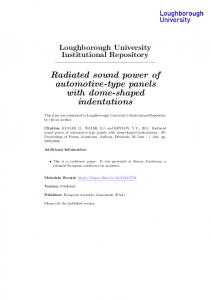
Figure 1: Antenna measurement system. SATIMO SG-64, multi-probe spherical near field antenna test range.
3.2 Active testing In active testing the measurement is conducted by establishing a communication link to the device under test (AUT). Levels of both Effective Isotropic Radiated Power (EIRP) and Effective Isotropic Sensitivity (EIS) are measured in an anechoic chamber over a full spherical surface surrounding the device under test (DUT). Total Radiated Power (TRP) and Total Isotropic Sensitivity (TIS) can be derived from the EIRP and EIS data respectively. In active testing, the phase information of the measured field is not available and the propagation model imposed is uniform/isotropic. However, the complex working of the applied switching is included in the measurements by the active device. An example of TIS measurements on a dual receiver CDMA 2000 Radio system equipped with two external 880 MHz dipoles are shown in Figure 2. The external dipoles allow the user to experiment with different separation distances of the antennas to optimise the functionality of the system.
Figure 2: Example of TIS measurements on a CDMA 2000 Radio system equipped with two external 880 MHz dipoles for different dipole spacing. Dual receivers systems have the possibility to combine signals received from the two antennas in such a way as to maximum S/N or C/I ratio. With a two antenna system of completely uncorrelated and equally efficient antennas, TIS should theoretically increase by 3dB. It has been seen that in the presence of coherent interferers, the increase in TIS can be very high (even 10dB).
Figure 3: Example of TIS measurements on a notebook equipped with CDMA 2000 Radio system and two external antennas for different antenna spacing.
4. Comments, conclusions and future work As discussed in this paper, the phase information is generally not available for active measurements in the data acquisition stage. However, in some cases the phase can be retrieved from receives so that correlation analysis using different user defined propagation models can be used. Another method consists in emulating a realistic propagation environment defined by the user in which multi-path and interferers are present. The basic principle of spatial fading emulator for handset antennas could be used as a starting point for developing a standard in which propagation environment is taken into account [5]. A candidate 4-channels simulator currently being investigated by SATIMO based on fast multi-probes technology is shown in Figure 4. In the simulator, the multiple probes are used simultaneously to measured the direct link and emulate multi-path and interference. The proposed full OTA Channel Emulators could offer complete end-to-end testing of terminals over the air In the future. However, there is a clear need to limit the number of degrees of freedom to reduce test time. In the meantime, standard OTA testing delivers useful information for testing MIMO/Diversity Terminals, provided it includes: I. Testing with single antenna to identify platform coherent interferers II. Comparisons of single antenna with diversity/MIMO enabled
Figure 4: Proposed OTA channel emulator for MIMO testing using multiple probe technology with multi-path and interference emulation.
References [1] Tokio Taga, “Characteristics of Space Diversity Branch Using Parallel Dipole Antennas in Mobile Radio Communications”, Electronics and Communications in Japan, Part 1, Vol.76, No. 9, 1993 [2] Koichi Ogawa, “An Analysis of Performance of a Handset Diversity Antenna Influenced by Head, Hand, and Shoulder Effect at 900MHz; Part II-Correlation Characteristics”, IEEE Transactions on Vehicular Technology, Vol.50, No. 3, May 2001 [3] Breit, et al, “Design Guidelines for Mobile Antenna Diversity in Handsets”, QUALCOMM document 80-H3319-1, Rev B, March 2004 [4] Gurelli, M.I., Black, P.J., Attar, R.A. “CDMA2000 1xEV-DO forward link throughput sensitivity to diversity antenna correlations”, IEEE Globecom, 2003. [5] H.Iwai, A.Yamamoto, T.Sakata, K.Ogawa, K.Sakaguchi, and K.Araki, “Spatial Fading Emulator for Handset Antennas”, IEEE 2005. [6] Vaughan R., Andersen J. B., Channels, Propagation, and Antennas for mobile Communications, IEE, London 2003