Radiative flux from a planar multiple point source within a cylindrical enclosure reaching a coaxial circular plane Stanislaw Tryka Laboratory of Physics, Department of Agricultural Sciences, University of Agriculture in Lublin, Szczebrzeska 102, PL-22-400 Zamosc, Poland
[email protected]
Abstract: A general formula and some special integral formulas were presented for calculating radiative fluxes incident on a circular plane from a planar multiple point source within a coaxial cylindrical enclosure perpendicular to the source. These formula were obtained for radiation propagating in a homogeneous isotropic medium assuming that the lateral surface of the enclosure completely absorbs the incident radiation. Exemplary results were computed numerically and illustrated with threedimensional surface plots. The formulas presented are suitable for determining fluxes of radiation reaching planar circular detectors, collectors or other planar circular elements from systems of laser diodes, light emitting diodes and fiber lamps within cylindrical enclosures, as well as small biological emitters (bacteria, fungi, yeast, etc.) distributed on planar bases of open nontransparent cylindrical containers. ©2007 Optical Society of America OCIS codes: (030.5620) Radiative transfer; (080.2720) Geometrical optics; mathematical models; (120.5240) Photometry; (120.5630) Radiometry; (230.6080) Sources; (350.5610) Radiation
References and Links 1. 2. 3. 4. 5. 6. 7. 8. 9. 10. 11. 12. 13. 14. 15.
V.P. Gribkovskii, “Injection lasers,” Prog. Quant. Electr. 23, 41-88 (1995). A.C. Schuerger, C.S. Brown and E.C. Stryjewski, “Anatomical futures of pepper plants (Capsicum annuum L.) grown under red light emitting diodes supplemented with blue or far-red light,” Ann. Botany 79, 273282 (1997). R. Szweda, “Lasers at the cutting edge,” III-Vs Rev. 12, 28-31 (1999). L. Botter-Jensen, E. Bulur, G.A.T. Duller and A.S. Murray, “Advances in luminescence instrument systems,” Radiat. Meas. 32, 523-528 (2000). O. Monje, G.W. Stutte, G.D. Goins, D.M. Porterfield and G.E. Bingham, “Farming in space: environmental and biophysical concerns,” Adv. Space. Res. 31, 151-167 (2003). K.T. Lau, W.S. Yerazunis, R.L. Shepherd and D. Diamond, “Quantitative colorimetric analysis of dye mixtures using an optical photometer based on LED array,” Sens. Actuators B-Chem. 114, 819-825 (2006). S. Nakamura, S. Pearton and G. Fasol, The blue laser diode: The complete story (Springer-Verlag, Berlin, 2000). C. Curachi, A.M. Toboy, D.V. Magalhaes and V.S. Bagnato, “Hardness evaluation of a dental composite polymerized with experimental LED-based devices,” Dent. Mat. 17, 309-315 (2001). G. Glickman, B. Byrne, C. Pineda, W.W. Hauck and G.C. Brainard, “Light therapy for seasonal affective disorder with blue narrow-band light-emitting diodes (LEDs),” Biol. Psych. 59, 502-507 (2006). A. Juzeniene, P. Juzenas, L.-W. Ma, V. Iani and J. Moan, “Effectiveness of different light sources for 5aminolevolinic acid photodynamic therapy,” Lasers Med. Sci. 19, 139-149 (2004). B. Link, S. Ruhl, A. Peters, A. Junemann and F.K. Horn, “Pattern reversal ERG and VEP – comparison of stimulation by LED, monitor and a Maxwellian-view system,” Doc. Opthalmol. 12, 1-11 (2006). J.M. Gaines, “Modeling of multichip LED packages for illumination,” Lighting Res. Technol. 38, 152-165 (2006). A. Mills, “Trends in HB-LED markets,” III-Vs Rev. 14, 38-42 (2001). C. Gardner, “The use of misuse of coloured light in the urban environment,” Opt. Lasers Tech. 38, 366-376 (2006). A. Zukauskas, R. Vaicekauskas, F. Ivanauskas, R. Gaska and M.S. Shur, “Optimization of white polychromic semiconductors lamps,” Appl. Phys. Lett. 80, 234-236 (2002).
#75602 - $15.00 USD
(C) 2007 OSA
Received 29 September 2006; revised 16 February 2007; accepted 1 March 2007
2 April 2007 / Vol. 15, No. 7 / OPTICS EXPRESS 3777
16. F Grum and R.J. Becherer, Radiometry (Academic Press, New York, 1979) pp. 30-52, 81-83. 17. M. Strojnik and G Paez, “Radiometry” in Handbook of Optical Engineering, D. Malacara and B. J. Thompson eds. (Marcel Dekker, New York, 2001) pp. 649-699. 18. E. Sparrow and R. Cess, Radiation Heat Transfer, (McGraw-Hill, New York, 1978) pp. 77-136. 19. D.H. Sliney, “Laser effect on vision and ocular exposure limit,” App. Occup. Environ. Hyg. 11, 313-319 (1996). 20. T.R. Fry, “Laser safety,” Vet. Clin. Small Anim. 32, 535-547 (2002). 21. S. Tryka, “Angular distribution of the solid angle at a point subtended by a circular disk,” Optics Comm. 137, 317-333 (1997). 22. S. Tryka, “Angular distribution of an average solid angle subtended by a circular disc from multiple points uniformly distributed on planar circular surface coaxial to the disc,” J. Mod. Opt. 47, 769-791 (2000). 23. S. Wolfram, Mathematica-A System for Doing Mathematics by Computer (Addison-Wesley, Reading, Mass. 1993), pp. 44-186.
1. Introduction With increased development of solid state lighting there is currently a great deal of interest in the use of laser diodes (LDs) and light emitting diodes (LEDs) to make LD and LED arrays and multi LED lamps. LD and LED arrays have already found numerous laboratorial [1-6], industrial [3, 7], medical [1, 3, 8, 9] and domestic applications [1, 3, 7], while multi LED lamps are used in agriculture [2, 5] medicine [8, 9-11] and as sources of white or colored lights for illumination. In addition, LED lamps are used at present for general illumination, landscape lighting, automotive lighting, and as indicators and portable flashlights [13, 14]. By combining high-power and high-brightness blue, green and red LEDs, LED full-color displays and lamps with high reliability, high durability and low energy consumption are now possible [7, 13-15]. The LED-based displays and lamps effectively replace the traditional bulbs and fluorescent lamps and will probably be the most popular and frequently used sources of light in the near future [7, 12-15]. However, in contrast to traditional extended light sources, LEDs and LDs are in fact multiple point sources even when are positioned at small distance from the irradiated objects. In many applications of electromagnetic and corpuscular radiation it is necessary to calculate the radiative flux (the flux of radiation), or in other words the radiative power (the power of radiation) emitted by a given source and incident on an object of a given geometrical shape. Such calculations are necessary for measuring the fluxes of radiation incident on detectors and/or collectors [16-18] and for designing light sources for medical [8, 9] and agricultural [2, 5] experiments and uses. By using LEDs it is very simple to obtain multiple point sources of various geometrical shapes. However, when the high brightness multi LED sources are used the high power narrow-band radiations from individual or all LEDs may be hazardous to human and animal eyes. To protect humans and animals against ocular hazards the radiative fluxes incident on their eyes must be known [19, 20]. Therefore in a wide variety of practical applications of LD and LED arrays as well as LED lamps mathematical formulas related to various shapes of multiple point sources are indispensable. This paper presents one general and some special mathematical formulas for calculating fluxes of radiation reaching planar circular elements from planar multiple point sources within a coaxial circular enclosure perpendicular to the source plane. These formulas were obtained for radiation propagated in a homogeneous attenuating medium when the lateral surface of the enclosure completely absorbs the incident radiation. The analyzed model of the multiple point source may represent LED and LD arrays, fiber sources within cylindrical enclosures or small biological objects emitting photons enclosed within open cylindrical containers. All presented formulas are directly applicable to planar coaxial circular multiple point source-detector and source-collector systems, for example. 2. Definition of variables and some fundamental expressions The cylindrical coordinate system, 0ρϕz, was used to obtain the mathematical formulas presented in the paper. The geometry of the analyzed optical system is shown schematically in
#75602 - $15.00 USD
(C) 2007 OSA
Received 29 September 2006; revised 16 February 2007; accepted 1 March 2007
2 April 2007 / Vol. 15, No. 7 / OPTICS EXPRESS 3778
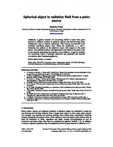
Fig. 1. Throughout the paper we assume that the multiple point source of the surface, σ, and illuminated circular planar surface, S, are separated by a homogeneous isotropic medium and that the lateral surface of the enclosure completely absorbs the incident radiation so that only the radiation leaving the enclosure through its open end reaches the surface S. The radiative flux, Φσ→S, enclosed within the spectral region between wavelengths λmin and λmax and incident on the surface S from the planar circular coaxial multiple point source of surface σ can be calculated as [17]
Φσ →S =
λ max
∫ λ min
Φλ,σ →S d λ ,
(1)
where Φλ, σ→S = dΦσ→S / dλ is the spectral radiative flux of wavelength λ from all point emitters given by
Φλ,σ →S =
∑ ∑Φ
N λ , ρ N λ ,φ
i =1 j =1
λ , P→S
( ρi , φj ).
(2)
The function Φλ, P→S (ρi, φj) in the above equation represents the spectral radiative flux at wavelength λ reaching the plane S from the single point emitter P(ρi, φj) while the symbols Nλ, ρ and N λ, φ denote the number of point emitters radiating at wavelength λ and positioned at radial distances ρi and horizontal angles φj, respectively.
Fig. 1. Definition of some geometrical variables and the perspective view of the planar circular multiple point source of surface σ within the cylindrical enclosure contributing optical radiation to the planar circular coaxial surface S when a ≤ R and H > h (a) and the scheme of the σ-S system when a > R and H > h (b). The symbol r denotes the radial distance between the points P( ρi, φj) and P/( ρi, φj, r, ϕ).
The radiative flux Φλ, P→S (ρi, φj) incident on the surface S from the single point emitter P(ρi, φj) is described by
Φλ, P→S ( ρi ,φ j ) =
∫∫
I λ, P / (ρi ,φj ,θ ,ϕ, H,αat ) dωP −d S / (θ ,ϕ ) ,
(3)
S/
where Iλ, P (ρi, φj, θ, ϕ, H, αλ, at) denotes the radiant intensity of wavelength λ at the point where P / (ρi, φj, r, ϕ) and dωP-dS(θ, ϕ) is an infinitesimal solid angle subtended at P by the surface element dS / and is given as follows d ωP−d S / (θ ,ϕ ) = sin θ dθ dϕ .
#75602 - $15.00 USD
(C) 2007 OSA
(4)
Received 29 September 2006; revised 16 February 2007; accepted 1 March 2007
2 April 2007 / Vol. 15, No. 7 / OPTICS EXPRESS 3779
S / represents the surface S or its part limited by the rays passing through the upper edge of the cylindrical enclosure. The symbol αλ, at denotes the coefficient describing the attenuation of the radiation along the ray between P(ρi, φj) and P / (ρi, φj, r, ϕ) usually expressed as [16, 17] α λ ,at = α λ, ab + α λ, sc ,
where αλ, ab and αλ, sc are the absorption and scattering coefficients, respectively. In a homogeneous medium the intensity Iλ, P (ρi, φj, θ, ϕ, H, αλ, at) obeys the Bouguer–Lambert exponential law of intensity attenuation [16] I λ , P / (ρi ,φ j ,θ ,ϕ, H,α λ, at ) = I λ , P (ρi ,φ j ,θ ,ϕ) τ P / (θ , H ,α λ , at ),
(5)
where Iλ, P (ρi, φj, θ, ϕ) is the intensity of radiation emitted by the emitter P(ρi, φj) and τ P (θ , H ,α λ , at ) = exp ( − H α λ, at / cos θ ) , /
0 ≤ θ < π / 2,
(6)
is the internal transmittance. 3. The radiative flux reaching the circular plane from the single point emitter within a coaxial cylindrical enclosure Substituting Eqs. (4) and (5) into (3) leads to the integral
Φλ, P→S ( ρi ,φ j ) =
∫∫
I λ, P (ρi ,φj ,θ ,ϕ) τ P / (θ , H,αλ, at ) sin θ dθ dϕ ,
(7)
S/
which can be calculated similarly to the integral in Eqs. (2.7) from Ref. [21]. This way, for the boundary conditions made by the external contour of the circular surface S with the radius R and by the top circular edge of the cylindrical enclosure with the radius a, as shown in Fig. 1, we obtain a set of seven double-definite integral expressions: Φλ , P →S ( ρi , φ j ) =
π /2
∫
0
2π
sin θ d θ ∫ I λ , P (θ ,ϕ ) d ϕ , ρ i = 0, 0
(8a)
if h = H = 0 and a = 0, Φλ , P →S ( ρi , φ j ) = 0, ρ i = 0,
(8b)
if 0 < h ≤ H and a = 0, Φλ , P →S ( ρi , φ j ) =
π /2
∫
0
2π
sin θ d θ ∫ I λ , P (θ ,ϕ ) d ϕ , ρ i = 0, 0
(8c)
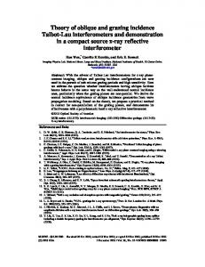
if h = H= 0 and a > 0, ⎧ θ a τ / (θ , H ,α )sin θ d θ 2π I (θ ,ϕ )d ϕ , 0= ρi R (b). The radial distance r is defined as r = h tan θ (a) and as r = H tan θ (b).
Equations (8a)-(8g) represent the general double-integral solution to the spectral radiative flux Φλ, P→S(ρi, φj) reaching the planar circular surface S from a given point emitter P(ρi, φj) within the coaxial cylindrical enclosure perpendicular to the source σ provided that the lateral surface of the enclosure completely absorbs the incident radiation. Putting R = ∞ in Eqs. (8a)(8g) and assuming that the radius a, height h and distance H are not infinite, we obtain Eqs. (8a)-(8d) for calculating the total radiative fluxes, Φλ, σ (ρi, φj), at wavelength λ emitted by any point emitter P(ρi, φj) into the space surrounding the cylindrical enclosure. The solutions represented by Eqs. (8a)-(8g) are appropriate for calculating the flux Φλ, σ→S from Eq. (2) for arbitrary distributed point emitters P(ρi, φj) composing the source σ within the cylindrical enclosure if the attenuation coefficient αλ, at of the homogeneous medium is defined and the radiant intensities Iλ, P (ρi, φj, θ, ϕ) from each point emitter are known. However the radiative fluxes Φλ, P→S(ρi, φj) in Eq. (2) must be calculated at given wavelengths λ from Eqs. (8a)-(8g). Obviously by substituting Eqs. (8a)-(8d) into (2) at R = ∞ and finite a, h and H, we obtain a formula for calculating the radiative flux, Φλ, σ, emitted by the source σ into the space surrounding this source within the enclosure. For many functions Iλ,P (ρi, φj, θ, ϕ) Eqs. (8a)-(8g) can be integrated with respect to the angle ϕ and expressed by single definite integrals. Even though these equations can be expressed by single definite integrals, further computation of the radiative fluxes Φλ, σ→S for #75602 - $15.00 USD
(C) 2007 OSA
Received 29 September 2006; revised 16 February 2007; accepted 1 March 2007
2 April 2007 / Vol. 15, No. 7 / OPTICS EXPRESS 3782
large numbers of emitters P(ρi, φj) composing the source σ from general Eq. (2) may be timeconsuming and impractical. Therefore, it is desirable to look for a simpler analytical solution to the problem outlined above. We obtain such a solution when the emitters P(ρi, φj) are spread uniformly and each of them emits identically angularly distributed radiation. 4. Identically radiating emitters of a uniformly spread multiple point source Equation (2) can also be rewritten as Φλ ,σ →S = N λ ,
(11)
where Nλ represents the total number of point emitters radiating at wavelength λ and 1 Nλ
=
∑ ∑Φ
N λ , ρ N λ ,φ
λ, P→S
i =1 j =1
( ρi ,φ j ),
(12)
is the average radiative flux from all point emitters P(ρi, φj) radiating at wavelength λ. For identically radiating emitters P(ρi, φj) from a uniformly distributed multiple point source we can divide the surface σ into the surface elements π ( ρ i2 − ρ i2−1 ) containing Nλ(ρi) emitters so that
∑ N (ρ ) = N , ∑ ( ρ −ρ m
m
λ
i =1
λ
i
i −1
i
i =1
) =
∑ Δρ m
= a,
i
i =1
where m is the number of elements Δρi and a is the radius of the source σ or radius of the cylindrical enclosure. Then due to the uniform distribution we have Nλ ( ρi )/ (2π ρi Δρi ) = Nλ ( π a 2 )
and for R > 0 Eq. (12) obtains the following form ⎧ π / 2 sinθ dθ 2π I (θ ,ϕ )dϕ , h = H = 0, ∫ 0 λ, P ⎪ ∫0 = ⎨ ⎪ 0, 0 0, where Φλ, P→S(ρi) is the radiative flux from the point emitter P(ρi) lying at a distance ρi. For extremely small elements Δρi → 0 we obtain m → ∞ so that Eq. (14) becomes 2 a2
=
a
∫ 0 Φλ , P→S ( ρ ) ρ d ρ ,
0 < h ≤ H.
(15)
To integrate Eq. (15) we can use the method for calculating the average solid angle subtended by a circular disk from uniformly spread multiple points on the coaxial circular plane described in Ref. [22] during integration of Eq. (22). Applying to Eq. (15) the boundary conditions made by the geometrical variables defined in Figs. 1(a) and (b) we get =
#75602 - $15.00 USD
(C) 2007 OSA
2 a2
arctan (a / h)
⎡ ⎢⎣ ∫ 0
0
τ P (θ ,H ,α λ, at )sinθ dθ ∫
a − h tan θ
/
arctan (a / h)
+∫
0
+∫
arctan ( a / h)
a − h tan θ
τ P (θ , H ,α λ, at )sinθ dθ ∫ /
arctan (2a / h)
τ P (θ ,H ,α λ, at )sinθ dθ /
a
a
ρ dρ ∫
ρ dρ ∫
2π 0
I λ, P (θ ,ϕ)dϕ
γ a, ρ −γ a, ρ
γ a, ρ
I λ, P (θ ,ϕ)d ϕ
∫ h tan θ − a ρ d ρ ∫ −γ a, ρ
I λ, P (θ ,ϕ)d ϕ⎤ , ⎥ ⎦
(16a)
Received 29 September 2006; revised 16 February 2007; accepted 1 March 2007
2 April 2007 / Vol. 15, No. 7 / OPTICS EXPRESS 3783
if 0 < a ≤ h R/(2H - h) ≤ R, =
⎡ arctan ( a / h )τ (θ ,H ,α )sin θ dθ a − h tan θ ρ d ρ λ , at ∫0 ∫ P/ ⎢⎣∫ 0
2 a2
arctan ( a / h)
a
τ P (θ , H,α λ, at )sinθ dθ ∫
+∫
0
+∫
arctan ( a / h)
+∫
arctan [( a + Y )/ h]
/
τ P (θ ,H ,α λ, at )sinθ dθ ∫ /
a
τ P (θ ,H ,α λ, at )sinθ dθ /
a
∫
H tan θ − R
I λ, P (θ ,ϕ)dϕ
−γ a , ρ
γ a, ρ
ρdρ∫
h tan θ − a
arctan [( R + a)/ H ]
I P (θ ,ϕ)dϕ
γ a, ρ
ρdρ∫
a − h tan θ
arctan [( a + Y )/ h]
2π 0
−γ a, ρ
I λ, P (θ ,ϕ ) d ϕ
γ R, ρ
ρdρ∫
−γ R, ρ
I λ, P (θ ,ϕ)dϕ ⎤ , ⎥ ⎦
(16b)
if 0 < R ≤ h R/(2H - h) ≤ a ≤ h R/H, =
a − h tan θ
arctan [( R + Y )/ H ]
2 a2
⎡ ⎢⎣∫ 0
+∫
τ P (θ ,H ,α λ, at )sinθ dθ ∫
0
τ (θ ,H ,α λ,at )sinθ dθ ∫
0
/
arctan ( R / H )
R − H tan θ
/ arctan [( R + Y )/ H ] P
arctan ( R / H )
τ (θ ,H ,α λ, at )sinθ dθ ∫
R − H tan θ
τ (θ ,H ,α λ, at )sinθ dθ ∫
−Y
+∫
/ arctan [( R + Y ) / H ] P
+∫
/ arctan [( R + Y ) / H ] P
arctan ( R / H )
arctan ( R / H )
+∫
0
+∫
arctan ( R / H )
−Y
τ P (θ ,H ,α λ, at )sinθ dθ ∫ /
a − h tan θ
a a − h tan θ
arctan [( R + a) / H ]
0
ρdρ∫
0
∫
/
I λ, P (θ ,ϕ)dϕ
2π
I λ, P (θ ,ϕ)dϕ
γ, R, ρ
ρdρ∫
−γ R, ρ
ρdρ∫
−γ a, ρ
ρdρ∫
a
τ P (θ ,H ,α λ, at )sinθ dθ
2π
ρdρ∫
H tan θ − R
γ a, ρ
γ a, ρ −γ a , ρ
ρdρ∫
I λ, P (θ ,ϕ)dϕ I λ, P (θ ,ϕ)d ϕ
I λ, P (θ ,ϕ)dϕ γ R, ρ −γ R, ρ
I λ, P (θ ,ϕ)d ϕ⎤ , ⎥ ⎦
(16c)
if 0 < h R/H < a < R, =
2 a2
arctan ( R / H )
⎡ ⎢ ⎣∫0
τ P (θ ,H ,α λ, at )sinθ dθ /
arctan ( R / H )
R − H tan θ
∫0
τ P (θ ,H ,α λ, at )sinθ dθ ∫
+∫
0
+∫
arctan ( R / H )
+∫
arctan [( a − R )/ H ]
/
R + H tan θ R − H tan θ
τ P (θ ,H,α λ , at )sin θ dθ ∫ /
/
ρdρ∫
−γ R, ρ
H tan θ − R
arctan [( R + a )/ H ]
τ P (θ ,H ,α λ, at )sinθ dθ
0
R + H tan θ
arctan [( a − R )/ H ]
a
∫
2π
ρdρ ∫
H tan θ − R
I λ , P (θ ,ϕ) d ϕ
γ R, ρ
I λ, P (θ ,ϕ) dϕ
γ R, ρ
ρdρ∫
− γ R, ρ
ρdρ ∫
−γ R, ρ
γ R, ρ
I λ , P (θ ,ϕ) d ϕ I λ, P (θ ,ϕ) dϕ ⎤⎥ , ⎦
(16d)
if 0 < R ≤ a/2, and =
2 a2
arctan ( R / H )
⎡ ⎢⎣ ∫ 0
τ P (θ ,H ,α λ , at )sinθ dθ /
R − H tan θ
∫0
R + H tan θ
arctan [(a − R) / H ]
τ P (θ ,H ,α λ, at )sinθ dθ ∫
R − H tan θ
τ (θ ,H ,α λ, at )sinθ dθ ∫
R − H tan θ
+∫
0
+∫
/ arctan [(a − R) / H ] P
+∫
arctan ( R / H )
/
arctan ( R / H )
ρ dρ ∫
a
arctan [( R + a ) / H ]
τ P (θ ,H,α λ , at )sinθ dθ /
ρ dρ ∫
ρ dρ∫
a
∫
2π 0
H tan θ − R
I λ , P (θ ,ϕ)dϕ γ R, ρ −γ R , ρ
γ R ,ρ − γ, R , ρ
ρ dρ∫
γ R, ρ −γ R, ρ
I λ, P (θ ,ϕ)dϕ I λ, P (θ ,ϕ)dϕ I λ, P (θ ,ϕ)dϕ ⎤ , ⎥⎦
(16e)
if 0 < a/2 < R < a. The limiting angles γ a , ρ and γ R , ρ are described by Eqs. (9a)-(9b) without the subscript i. Formulas (13) and (16a)-(16e) enable calculation of the average radiative fluxes from any uniformly distributed multiple point source, provided that each point emitter of this source identically emits angularly distributed radiation with respect to the zaxis. When the number Nλ of point emitters is known it is simple to obtain the total spectral radiative flux Φλ, σ→S using Eq. (11). The average radiative flux, , emitted into the space surrounding the source σ within a cylindrical enclosure is described by Eqs. (13) and (16a) because the remaining Eqs. #75602 - $15.00 USD
(C) 2007 OSA
Received 29 September 2006; revised 16 February 2007; accepted 1 March 2007
2 April 2007 / Vol. 15, No. 7 / OPTICS EXPRESS 3784
(16b)-(16e) disappear for R = ∞ and finite values of a, h, and H. For the intensity Iλ, P (θ, ϕ) not dependent on the horizontal angle ϕ, as in the case of radiation rotationally symmetrical around z-axis, the inner integrals with respect to the angle ϕ and distance ρ in Eqs. (16a)-(16e) can be expressed by simple elementary functions and we obtain single integral solutions to Eq. (12). In the following two subsections, we present such solutions for radiation not dependent on the angle ϕ and then for isotropic radiation. 4.1 Rotationally symmetrical radiation with respect to the z-axis For the radiant intensity Iλ, P (θ, ϕ) not dependent on the horizontal angle ϕ we have Iλ, P (θ, ϕ) = Iλ, P (θ) and Eqs. (13) and (16a)-(16e) simplify to ⎧ 2π π / 2 I (θ )sinθ dθ , h = H = 0, λ, P ∫0 ⎪ = ⎨ ⎪ 0, 0< h≤ H, ⎩
(17a)
if a = 0, =
2 a2
∫0
2 a2
⎡ ⎢⎣ ∫
arctan (2 a / h)
I λ, P (θ )τ P / (θ ,H ,α λ, at ) ga,a (θ , a, h ) sinθ dθ ,
(17b)
if 0 < a ≤ h R/(2H - h) ≤ R, =
+∫
arctan [( a +Y )/ h] 0 arctan[( R + a )/ H ] arctan[( a +Y )/ h]
I λ, P (θ )τ P / (θ ,H ,α λ, at ) ga, a (θ ,a,h) sin θ dθ I λ, P (θ )τ P / (θ , H ,α λ, at ) gR, a (θ ,R,a,H ) sinθ dθ ⎤ , ⎥ ⎦
(17c)
if 0 < R ≤ h R/(2H - h) ≤ a ≤ h R/H, =
2 a2
arctan ( R / H )
⎡ ⎢⎣ ∫ 0
+ − +
I λ, P (θ )τ P / (θ ,H ,α λ, at ) ga, a (θ ,a ,h) sinθ dθ
arctan ( R / H )
∫ arctan[( R+Y )/ H ] arctan ( R / H )
∫ arctan[( R +Y )/ H ] arctan[( R + a)/ H ]
∫ arctan ( R / H )
I λ, P (θ )τ P / (θ , H,α λ, at ) gR,Y (θ ,R,a,H ) sinθ dθ I λ, P (θ )τ P / (θ ,H ,α λ, at ) ga,Y (θ ,a,h) sinθ dθ I λ, P (θ )τ P / (θ , H ,α λ, at ) gR, a (θ ,R,a,H ) sin θ dθ ⎤ , ⎥ ⎦
(17d)
if 0 < h R/H < a < R, =
arctan [(a − R )/ H ] 2 ⎡ π R2 ∫ I λ, P (θ ) τ P / (θ ,H ,α λ, at )sinθ dθ 0 a 2 ⎢⎣
+∫
arctan [( R + a ) / H ] arctan [( a − R ) / H ]
I λ , P (θ ) τ P / (θ ,H ,α λ, at ) gR, a (θ ,R,a,H ) sinθ dθ ⎤ , ⎥⎦
(17e)
if 0 < R < a, where ga,a (θ , a, h ) = 2 a 2 arccos [ h tan θ (2 a ) ] − ⎡a
ga,Y (θ ,R,a, H ) = Y 2 arccos ⎢ ⎣
2
1 h tanθ 2
4 a 2 − h 2 tan 2 θ ,
2 2 2 2 ⎡ a + h tan θ −Y ⎤ − h 2 tan 2 θ −Y 2 ⎤ 2 ⎥ + a arccos ⎢ ⎥ 2Y h tanθ 2 ah tanθ ⎦ ⎣ ⎦
1 [(a −Y ) 2 − h 2 tan 2 θ ][ h 2 tan 2 θ − (a +Y ) 2 ], − 2
#75602 - $15.00 USD
(C) 2007 OSA
Received 29 September 2006; revised 16 February 2007; accepted 1 March 2007
2 April 2007 / Vol. 15, No. 7 / OPTICS EXPRESS 3785
⎡R
gR,Y (θ , R,a, H ) = Y 2 arccos ⎢ ⎣
2
2 2 2 2 ⎡ R + H tan θ −Y ⎤ − H 2 tan 2 θ −Y 2 ⎤ 2 ⎥ + R arccos ⎢ ⎥ 2Y H tanθ 2 R H tanθ ⎦ ⎣ ⎦
1 [(R −Y ) 2 − H 2 tan 2 θ ][ H 2 tan 2 θ − (R +Y ) 2 ], − 2 ⎛a
gR,a (θ ,R,a,H ) = a 2 arccos ⎜ ⎝
2
2 2 2 2 ⎛ R + H tan θ − a ⎞ + H 2 tan 2 θ − R 2 ⎞ 2 ⎟ + R arccos ⎜ ⎟ 2 a H tanθ 2 RH tanθ ⎠ ⎝ ⎠
1 [(R + a) 2 − H 2 tan 2 θ ][ H 2 tan 2 θ − ( R − a) 2 ]. − 2
Equations (17a)-(17e) can be easily turned into a computer code for calculating the fluxes if the radiant intensity Iλ, P (θ) is defined. Figures 3(a)-3(d) demonstrate four examples of such calculations obtained for the point emitters of the source σ emitting rotationally symmetrical radiation around z-axis and when the radiant intensity is given by the expression Iλ, P (θ) = Iλ, 0 cos2θ. The data plotted in Figs. 3(a) and 3(c) were computed for nonattenuated radiation while the data shown in Figs. 3(b) and 3(d) were calculated for radiation attenuated within a homogeneous isotropic medium.
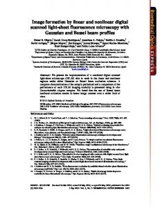
Fig. 3. The average spectral radiative flux within wavelength interval Δλ = 1 nm obtained for IP (θ1) = I0 cos2θ1 as a function of R and H at a = 5 and αat = 0 (a), as a function of R and H at a = 5 and αat = 0.1 (b), as a function of a and H at R = 5 and αat = 0 (c), and as a function of a and H at R = 5 and αat = 0.1 (d). The data were calculated for the relative units of R, a, H, and αat i.e. if R, a, and H are given in m then αat is expressed in m-1. The radiant intensity was taken as I0 = 1 W⋅sr-1, so the flux is given in W⋅nm-1.
Figures 3(a) and (3c) show that the flux in a non-attenuating medium is always greater at the lower distance H and clearly depends on both radii R and a. The flux shown in Fig. 3(a) increases with increased R and obtains maximal value at a small distance H in the region limited by the relation R > a. In Fig. 3(c) we observe that at a given distance H #75602 - $15.00 USD
(C) 2007 OSA
Received 29 September 2006; revised 16 February 2007; accepted 1 March 2007
2 April 2007 / Vol. 15, No. 7 / OPTICS EXPRESS 3786
the flux monotonically increases with increasing a until a ≤ R. Then the flux monotonically decreases. The flux of the radiation propagated in an attenuated homogeneous medium is dependent on the radii R, a, and distance H, similarly to the flux propagated in an non-attenuating medium. However, it is clearly seen that the fluxes in Figs. 3(b) and 3(d) are lower in comparison to those presented in Figs. 3(a) and 3(c) and this effect is due to the attenuation phenomena described by Eq. (6). The computer simulated surface-plots for the radiant intensity function Iλ, P (θ) = Iλ, 0 cosθ were similar to the plots in Figs. 3(a)-3(d) although the fluxes were varied within the wider ranges of the spectral power obtaining maximal values of 1.200 W nm-1 and 0.657 W nm-1 at Iλ, 0 = 1 W sr-1 within wavelength interval Δλ = 1 nm in a non-attenuating and attenuating medium respectively. Therefore from these data, it is easy to deduce that the fluxes reaching the surface S clearly depend on the angular distribution of the emitted radiation. Some representative data of the absolute radiative fluxes computed for Iλ, P (θ) = Iλ, 0 cos2θ and Iλ, P (θ) = Iλ, 0 cosθ with accuracy to twelve decimal places when the radii R and a, and height H were expressed in m and when the attenuation coefficient αat was expressed in m-1 are given in the fifth and sixth column of Table 1 in Appendix A. All these data were computed from Eqs. (17a)-(17e) for the radiant intensity Iλ, 0 = 1 W⋅sr-1. Therefore one can use the data from Table 1 for checking one’s own calculations from the formulas presented above. 4.2 Isotropic radiation Sometime the angular distribution of radiation emitted by point emitters is isotropic or is unknown and considered isotropic. In this case the intensity Iλ, P (θ) does not depend on the angle θ so that Iλ, P (θ) = Iλ, 0 and Eqs. (17a)-(17e) become ⎧ 2π I λ,0 , h = H = 0, ⎪ = ⎨ 0, 0 [W⋅nm ]
I0 [W⋅sr-1]
αλ, at ≥ 0
0
0
0
0
1.010574654656
1.199981614864
1.459023370479
0.1
0.897577227346
1.062817816361
1.287921394452
0
0.496874789412
0.539012084453
0.587516028953
0.1
0.400009739557
0.433486684100
0.471974166222
0
0.459790776267
0.599990807432
0.823338701585
0.1
0.403715990668
0.523355917770
0.712230027741
0
0.316507865759
0.368250521113
0.434444775946
0.1
0.250893035689
0.290974335820
0.342055669335
αλ, at ≥ 0
0
0
0
0
1.010574654656
1.199981614864
1.459023370479
0.1
0.897577227346
1.062817816361
1.287921394452
0
0.974697090431
1.136833076816
1.347370907053
0.1
0.772237767526
0.897357627023
1.059152394411
0
1.474277935433
1.915151942362
2.652058571880
0.1
1.295384037814
1.668857539856
2.283978113688
0
1.010574654656
1.199981614864
1.459023370479
0.1
0.797476179816
0.941710492772
1.137437305688
a
H
αλ, at
0
H≥h 1.0
1.0 2.0
1.0
1.0 2.0 2.0 0
H≥h 1.0
1.0 2.0
2.0
1.0 2.0 2.0
#75602 - $15.00 USD
(C) 2007 OSA
Received 29 September 2006; revised 16 February 2007; accepted 1 March 2007
2 April 2007 / Vol. 15, No. 7 / OPTICS EXPRESS 3790