Table 3. Series 4 Drive Faults. Fault Name. Short Code. Fuse. PUF ...
degradation detection. UL5. Current offset fault. COF. PLC fault 1. PE1. PLC fault
2. PE2 ...
Radio Drive Serial Interface (RDSI) Technical Specifications Magnetek’s Radio Drive Serial Interface is designed to communicate via a serial interface to directly control Magnetek’s IMPULSE®•G+/VG+ Series 3 and IMPULSE®•G+ Mini Adjustable Frequency Crane Controls (consult factory for compatibility if you have an existing RDSI setup with a Series 2 drive).
COMMUNICATION RDSI uses the Modbus RTU protocol over RS-485 to communicate between the radio receiver and the drive. This permits the receiver to serially command the drive. The receiver also has the ability to query the drive for feedback and present this to the user on the display of the transmitter. The RS-485 communication path is a multipoint communication while utilizing a four wire setup with TxD+, TxD-, RxD+, and RxD- for half duplex operation. The receiver communication card of the receiver has the ability to communicate directly with two drives. This means for every two drives a communication card is required on the Flex M.
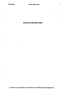
GETTING FEEDBACK Drive feedback is displayed on the display screen of the transmitter. If the transmitter does not have a display screen, the feedback option is not available. During normal operation, the display on the transmitter shows the command confirmation of how the transmitter is actively commanding the receiver to operate. The transmitter has a switch which permits for switching to the feedback screens for each drive. Feedback data from each drive is shown synchronously as each screen is cycled through. Upon changing to a new drive screen, the transmitter sends a message to the receiver querying it for the drive information. The receiver then queries the drive for the information and sends the data back to the transmitter where the data is shown on the display screen for the user. Faults and alarms from the drives are always shown asynchronously. These parameters are queried from the drive within 1000ms and are continually sent to the transmitter. HOW FEEDBACK IS DISPLAYED All of the feedback from the drives is shown on the display of the transmitter. The top line of the display always shows any faults and/or alarms regardless of which screen is being shown. If there are multiple faults and/or alarms, these are cycled through every 2 seconds. On the drive feedback screens, there are five lines of drive feedback parameters which are shown. RDSI MAIN SCREEN
FAULT D1: OL1 MAIN: 250 tons Aux: 100 tons
Alarm/Fault; see below for more info Main Hoist Weight Feedback Aux Hoist Weight Feedback
Bridge Fwd 80% Horn
Motion Commands Auxiliary commands
100% N49 W13650 Campbell Drive Menomonee Falls, WI 53051 Toll‐Free Phone 800.288.8178 Toll‐Free Fax 800.298.3503
P.O. Box 13615 Milwaukee, WI 53213 Phone 262.783.3500 Fax 262.783.3510
Enrange Facility #5 Four Coins Drive Canonsburg, PA 15317 Phone 800.288.8178 Fax 800.298.3503
Canada Facility 4090B Sladeview Crescent Mississauga, Ontario L5L 5Y5 Canada Toll Free Phone: 800.792.7253 Fax: 905.8281526
www.magnetekmh.com Brochure No. RDSI Technical Specifications
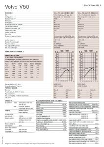
Radio Drive Serial Interface (RDSI) Technical Specifications RDSI DRIVE SCREEN
ALARM D1: UV DRIVE: 2 FREQ REF: XX.XX Hz OUT FREQ: XX.XX Hz OUT CRNT: XX.X AMP DRV STS: 0000 0000 100%
Line 1: Alarm/Fault; see below for more info Selected Drive Line 2: Frequency Reference Line 3: Output Frequency Line 4: Output Current Line 5: Drive Status D# indicates the drive’s address, abbreviated fault/alarm code
TYPES OF FEEDBACK RDSI offers the following feedback parameters as the standard parameters that are shown when a drive feedback screen is active. Drive Status Freq Reference Output Frequency Output Voltage Output Current Output Power Torque Reference Load Weight Any active drive alarms or faults are also shown on the display. Below is the list of alarms and faults that are shown. Table 1. Series 3 Drive Faults
Fault Name Fuse Blown DC Bus Undervoltage Control Circuit Undervoltage MC Answerback Ground Fault Overcurrent DC Bus Overvoltage Inverter Heatsink Overheat Inverter Heatsink Overheat Motor Overload Inverter Overload Overtorque 1 Overtorque 2 Braking Transistor Fault Internal Braking Resister Overheat N49 W13650 Campbell Drive Menomonee Falls, WI 53051 Toll‐Free Phone 800.288.8178 Toll‐Free Fax 800.298.3503
P.O. Box 13615 Milwaukee, WI 53213 Phone 262.783.3500 Fax 262.783.3510
Enrange Facility #5 Four Coins Drive Canonsburg, PA 15317 Phone 800.288.8178 Fax 800.298.3503
Short Code PUF UV1 UV2 UV3 GF OC OV OH OH1 OL1 OL2 OT1 OT2 RR RH Canada Facility 4090B Sladeview Crescent Mississauga, Ontario L5L 5Y5 Canada Toll Free Phone: 800.792.7253 Fax: 905.8281526
www.magnetekmh.com Brochure No. RDSI Technical Specifications
Radio Drive Serial Interface (RDSI) Technical Specifications Fault Name External Fault Terminal 3 External Fault Terminal 4 External Fault Terminal 5 External Fault Terminal 6 External Fault Terminal 7 External Fault Terminal 8 PG CH1 Open (Hardware Detection) CH1 Overspeed CH1 Speed Deviation PG CH1 Open (Software Detection) Input Phase Loss Output Phase Loss Motor Overheat 1 Operator Disconnected while B3-0 EEPROM Writing Error Motor Overheat 2 Memobus Communication Error Communication Option Error Control Fault Zero Servo Fault Communication Option External Fault PID Feedback Loss Undertorque 1 Undertorque 2 PG CH2 Open (Hardware Detection) CH2 Overspeed CH2 Speed Deviation PG CH2 Open (Software Detection) Snapped Shaft Load Check Error Rollback Detected No Current Brake Release No Good Brake Welded Upper Limit 3 Sync Fault Load Check Test mode timeout Pulse Feedback Deviation N49 W13650 Campbell Drive Menomonee Falls, WI 53051 Toll‐Free Phone 800.288.8178 Toll‐Free Fax 800.298.3503
P.O. Box 13615 Milwaukee, WI 53213 Phone 262.783.3500 Fax 262.783.3510
Enrange Facility #5 Four Coins Drive Canonsburg, PA 15317 Phone 800.288.8178 Fax 800.298.3503
Short Code EF3 EF4 EF5 EF6 EF7 EF8 PGO-1-H OS-1 DEV-1 PGO-1-S PF LF OH3 OPR ERR OH4 CE BUS CF SVE EF0 FBL UT1 UT2 PGO-2-H OS-2 DEV-2 PGO-2-S SNAP LC BE1 BE2 BE3 BE7 UL3 SYNC LC2 TEST Pulse-Dev Canada Facility 4090B Sladeview Crescent Mississauga, Ontario L5L 5Y5 Canada Toll Free Phone: 800.792.7253 Fax: 905.8281526
www.magnetekmh.com Brochure No. RDSI Technical Specifications
Radio Drive Serial Interface (RDSI) Technical Specifications Table 2. Series 3 Drive Alarms
Alarm Name DC Bus Undervoltage (No run command) DC Bus Overvoltage (No run command) Inverter Overheat Inverter Overheat Warning by MFDI '39H' Overtorque 1 Overtorque 2 External Fault (F/R simultaneously) External Baseblock External Fault Terminal 3 External Fault Terminal 4 External Fault Terminal 5 External Fault Terminal 6 External Fault Terminal 7 External Fault Terminal 8 Snapped Shaft CH1 Overspeed CH1 Speed Deviation PG CH1 Open (Software Detection) PG CH1 Open (Hardware Detection) Memobus Communication Error Communication Option Error Serial Comm has not been established (Communication Option) Load Check Error Brake Answerback Lost during run CH2 Speed Bias Exceeded Communication Option External Fault Motor Switch During Run PID Feedback Loss Serial Comm has not been established (Memobus) Undertorque 1 Undertorque 2 Communication TEST Error CH2 Overspeed Motor Overheat 1 Drive not Ready PG CH2 Disconnect (Software Detection) PG CH2 Disconnect (Hardware Detection) Brake Answer 1 (Start of Run) N49 W13650 Campbell Drive Menomonee Falls, WI 53051 Toll‐Free Phone 800.288.8178 Toll‐Free Fax 800.298.3503
P.O. Box 13615 Milwaukee, WI 53213 Phone 262.783.3500 Fax 262.783.3510
Enrange Facility #5 Four Coins Drive Canonsburg, PA 15317 Phone 800.288.8178 Fax 800.298.3503
Short Code UV OV OH OH2 OT1 OT2 EF BB EF3 EF4 EF5 EF6 EF7 EF8 SNAP OS-1 DEV-1 PGO-1-S PGO-1-H CE BUS CALL LC BE0 DEV-2 EF0 Can't SW FBL CALL UT1 UT2 SE OS-2 OH3 DNE PGO-2-S PGO-2-H BE4
Canada Facility 4090B Sladeview Crescent Mississauga, Ontario L5L 5Y5 Canada Toll Free Phone: 800.792.7253 Fax: 905.8281526
www.magnetekmh.com Brochure No. RDSI Technical Specifications
Radio Drive Serial Interface (RDSI) Technical Specifications Alarm Name Brake Answer 2 (End of Run) Brake Slipping Upper Limit 2 Lower Limit 2 Upper Limit 1 Lower Limit 1 Slack Cable Detect Maintenance Required Klixon Upper Limit 3 Brake Slipping (Load Catch) Sync Alarm (8120.x) Slave Not Ready Sync Mode and Load Share Mode Slack Cable detected Load Check BRAKE STAND - Brake Stand Alarm
Short Code BE5 BE6 UL2 LL2 UL1 LL1 SLC MNT KLX UL3 BE8 SYNC SNR LOAD SHARE SLC2 LC2 BRAKE STAND
Table 3. Series 4 Drive Faults
Fault Name Fuse Low-voltage main circuit Control power failure Inrush prevention circuit abnormality Load short Earth fault Overcurrent Overvoltage Heat sink Overheat Overheat 1 Motor overload Inverter overload Over-torque detection 1 Over-torque detection 2 Dynamic Braking Transistor Mounting type braking resistor overheating External Fault (input S3) External Fault (input S4) N49 W13650 Campbell Drive Menomonee Falls, WI 53051 Toll‐Free Phone 800.288.8178 Toll‐Free Fax 800.298.3503
P.O. Box 13615 Milwaukee, WI 53213 Phone 262.783.3500 Fax 262.783.3510
Enrange Facility #5 Four Coins Drive Canonsburg, PA 15317 Phone 800.288.8178 Fax 800.298.3503
Short Code PUF UV1 UV2 UV3 SC GF OC OV OH OH1 OL1 OL2 OT1 OT2 RR RH EF3 EF4 Canada Facility 4090B Sladeview Crescent Mississauga, Ontario L5L 5Y5 Canada Toll Free Phone: 800.792.7253 Fax: 905.8281526
www.magnetekmh.com Brochure No. RDSI Technical Specifications
Radio Drive Serial Interface (RDSI) Technical Specifications Fault Name External Fault (input S5) External Fault (input S6) External Fault (input S7) External Fault (input S8) Fan failure Overspeed Excessive speed deviation PGO-1-S PG Software Fault Input Phase Loss Output phase loss Motor Overheating Alarm Operator bad connection EEPROM write error Motor overheating fault Memobus transmission error Optional transmission error Control Fault Zero-Servo Error Optional external abnormality Undertorque Detection 1 Undertorque Detection 2 External Fault (input S9) External Fault (input S10) External Fault (input S11) External Fault (input S12) Main circuit capacitor neutral point potential error Z-Pulse Missing Z-Pulse ERR Tref sign ERR Direction ERR Abnormal Current Imbalance PG circuit abnormality External abnormalities (input S1) External abnormalities (input S2) Mechanical degradation detection Mechanical degradation detection Current offset fault PLC fault 1 PLC fault 2 N49 W13650 Campbell Drive Menomonee Falls, WI 53051 Toll‐Free Phone 800.288.8178 Toll‐Free Fax 800.298.3503
P.O. Box 13615 Milwaukee, WI 53213 Phone 262.783.3500 Fax 262.783.3510
Enrange Facility #5 Four Coins Drive Canonsburg, PA 15317 Phone 800.288.8178 Fax 800.298.3503
Short Code EF5 EF6 EF7 EF8 FAN OS1 DEV1 PGO1S PF LF OH3 OPR ERR OH4 CE BUS CF SVE EF0 UT1 UT2 EF9 EF10 EF11 EF12 VCF DV1 DV2 DV3 DV4 LF2 PGOH EF1 EF2 OL5 UL5 COF PE1 PE2 Canada Facility 4090B Sladeview Crescent Mississauga, Ontario L5L 5Y5 Canada Toll Free Phone: 800.792.7253 Fax: 905.8281526
www.magnetekmh.com Brochure No. RDSI Technical Specifications
Radio Drive Serial Interface (RDSI) Technical Specifications Fault Name Rollback Detect No Current Brake Release NG Snapped Shaft Load Check Brake Welded Upper Limit 3 Node Setup Error Out of Sync Test Mode Timeout Pulse Deviation
Short Code BE1 BE2 BE3 SNAP LC BE7 UL3 nSE SYNC TEST Pulse-Dev
Table 4. Series 4 Drive Alarms
Alarm Name Low-voltage main circuit Main circuit overvoltage Heat sink thermal Inverter overheating warning Over Torque 1 ESI change Over Torque 2 ESI change Simultaneous input forward and reverse rotation command BB external input External Fault 3 (input S3) External Fault 4 (input S4) External Fault 5 (input S5) External Fault 6 (input S6) External Fault 7 (input S7) External Fault 8 (input S8) Internal cooling fan failure Overspeed Excessive speed deviation Pulse Generator 1 Software Fault Pulse Generator 1 Hardware Fault Memobus transmission error Optional transmission error Waiting for communication Load Check Alarm ESI change ESI change N49 W13650 Campbell Drive Menomonee Falls, WI 53051 Toll‐Free Phone 800.288.8178 Toll‐Free Fax 800.298.3503
P.O. Box 13615 Milwaukee, WI 53213 Phone 262.783.3500 Fax 262.783.3510
Enrange Facility #5 Four Coins Drive Canonsburg, PA 15317 Phone 800.288.8178 Fax 800.298.3503
Short Code UV OV OH OH2 OT1 OT2 EF BB EF3 EF4 EF5 EF6 EF7 EF8 FAN OS1 DEV1 PGO1S PGO1H CE BUS CALL LC BE0
Canada Facility 4090B Sladeview Crescent Mississauga, Ontario L5L 5Y5 Canada Toll Free Phone: 800.792.7253 Fax: 905.8281526
www.magnetekmh.com Brochure No. RDSI Technical Specifications
Radio Drive Serial Interface (RDSI) Technical Specifications Alarm Name ESI change Driving motor switching Snapped Shaft Waiting for communication Undertorque Detection 1 Undertorque Detection 2 Transmission test mode error Memobus Motor overheating Drive Not Enabled PG Circuit 2 Hardware Fault PG Circuit 2 Software Fault Brake Answer failure (not open) Brake Answer failure (not close) Brake Slipping V1000 no use Current warnings CanOpen EEPROM data error External Fault (input S1) External Fault (input S2) Hard wire base block Hard wire base block Mechanical degradation detection Mechanical degradation detection PLC alarm 1 PLC alarm 2 Travel limit Upper Limit 2 Travel limit Lower Limit 2 Travel limit Upper Limit 1 Travel limit Lower Limit 1 Slack Cable Maintenance Timer Klixon Weight Limit (MFDI 12,62) Brake Slipping (Load Catch) Slack Cable 2 Load Check 2 Brake Stand
Short Code DEV2 RUN SnAP CALL UT1 UT2 SE OH3 DNE PGO2S PGO2H BE4 BE5 BE6 HCA EEP EF1 EF2 HBBF HBB OL5 UL5 PA1 PA2 UL2 LL2 UL1 LL1 SLC MNT OL8 UL3 BE8 SLC2 LC2 BS
Please contact Eugene Novak, Radio Controls Product Manager, or Ben Stoller, Radio Controls Director, with any additional questions. N49 W13650 Campbell Drive Menomonee Falls, WI 53051 Toll‐Free Phone 800.288.8178 Toll‐Free Fax 800.298.3503
P.O. Box 13615 Milwaukee, WI 53213 Phone 262.783.3500 Fax 262.783.3510
Enrange Facility #5 Four Coins Drive Canonsburg, PA 15317 Phone 800.288.8178 Fax 800.298.3503
Canada Facility 4090B Sladeview Crescent Mississauga, Ontario L5L 5Y5 Canada Toll Free Phone: 800.792.7253 Fax: 905.8281526
www.magnetekmh.com Brochure No. RDSI Technical Specifications