required amount of Channel State Information (CSI), making ... wireless system is to provide ubiquitous high data rate cover- age. ... will occur since relayed packets need two hops to be received. ... links can result in an unfair comparison as the additional delay .... with fixed time division, is a RSâaided centralized allocation,.
Radio Resource Allocation Algorithm for Relay–aided Cellular OFDMA System Megumi Kaneko∗# and Petar Popovski∗ ∗
Center for TeleInFrastructure (CTIF), Aalborg University Niels Jernes Vej 12, DK-9220 Aalborg, Denmark #
Graduate School of Informatics, Kyoto University Yoshida Honmachi Sakyo–ku, Kyoto, 606-8501, Japan Email: {mek|petarp}@kom.aau.dk Abstract— We address the problem of radio resource allocation in the Downlink (DL) of relay–aided cellular system, based on OFDMA transmission technology. There has been little work on specific resource allocation algorithms for this system in the literature, although these are the key elements for realizing the potential capacity and coverage increase offered by the relay. Therefore, we propose two resource allocation algorithms which improve the overall throughput and coverage compared to a system without relay. The advantage of our algorithms is that they perform well while minimizing the complexity and the required amount of Channel State Information (CSI), making them suitable for practical use.
I. I NTRODUCTION One of the key expectations for the 4th Generation (4G) wireless system is to provide ubiquitous high data rate coverage. During these recent years, a large part of the research has focused on Orthogonal Frequency Division Multiple Access (OFDMA) transmission technology, a very promising candidate for the physical layer in 4G cellular system, due to its inherent robustness against frequency–selective fading and its capacity for achieving high spectral efficiency. In this multiple access scheme, each subcarrier can be allocated to a different user which can best exploit the current channel condition, hence maximizing the achievable capacity [1]. But with the traditional cellular architecture, increasing the capacity along with the coverage would require the deployment of a large number of Base Stations (BS), which is very costly. However, introducing Relay Stations (RS) in each cell can alleviate this problem since the RS can forward high data rates in remote areas of the cell while keeping a low cost of infrastructure. But this potential gain in capacity and coverage is highly dependent on the radio resource allocation strategy, a topic which draws more and more attention of the research community [2]. Moreover, the combination of RS resource allocation with OFDMA offers an even more promising perspective as for increasing capacity and cell coverage. Some works on resource allocation for OFDMA relay systems can be found in the literature, but they mainly focus on multihop, infrastructure–less networks or else, only a single destination is considered [3] [4]. To the best of the authors’ knowledge, there has been little work in the literature on specific resource allocation schemes
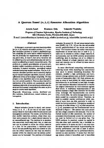
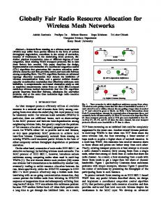
for multiple access in a RS–aided cellular system based on OFDMA technology. Thus, our goal is to provide efficient allocation algorithms for that system in the Downlink (DL), which enable a high capacity and high coverage with a low complexity. Also, one of the key points is that the algorithms are designed in such a way that reduces the required amount of Channel State Information (CSI). The remainder of the paper is organized as follows: after defining our system model, our path selection method is presented. This is followed by the description of our algorithms which are evaluated by simulations. Finally, we conclude the paper and give directions for future work. II. S YSTEM M ODEL In this work, we focus on the single cell DL transmissions with OFDMA, with one BS and one RS as depicted in Fig. 1. Users or Mobile Stations (MS) feed back to the BS or to the RS their CSI containing their per–subchannel Signal–to– Noise–Ratio (SNR) every time frame. A subchannel is defined as a group of adjacent subcarriers. Adaptive Modulation and Coding (AMC) is performed on a per–subchannel, per frame basis. We use the frame structure illustrated in 2, where there are: • Time division between BS and RS transmissions, with TBS the time allocated to the BS–Frame where transmissions from the BS occur and TRS is allocated to the RS– Frame where transmissions from the RS occur. Although suboptimal, we assume time division since it is widely considered in 802.16–based relay system [5]. • Frequency division between BS–MS and BS–RS transmissions, where each subchannel can be allocated to either link. • With this frame, the RS cannot receive and transmit the same packets during the same frame: 2 frames are needed to relay packets from the BS to the destination MS. To the best of our knowledge, this is a new but feasible type of structure as usually, the frequency regions for BS– MS and for BS–RS are fixed and separated. We focus on a two–hop scenario. Let us note that, the goal of this work is to design algorithms for allocating OFDMA resources in
the presence of a RS in a cell, when the CSI is reported. Hence, the principle of the presented algorithms remains the same when the neighboring cells are considered, perhaps with a lower performance (which is also the case for the reference algorithms, so the relative difference will be kept.)
Fig. 1.
Cell Model
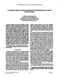
RS–MS link to this user and the capacity, proportional to the SNR on the RS–MS link would not be achieved. Thus, the method in [6] is reliable if there are always packets queued at the RS, which is not always true: in many cases the RS queues are empty and packets need to be forwarded from the BS to the RS. Here we introduce a measure for the effective data rate as opposed to the achievable data rate given by the SNR. We illustrate this observation in the following. We make the assumption that the RS queue is empty, which is the worst case. In this case, two frames are needed to transmit packets to a relayed user, the first frame for forwarding packets to the RS using the BS–RS link, and the second frame for providing the packets to destination, via the RS–MS link. This is because the RS can not receive and transmit the same packets in one frame. In the direct case, packets are transmitted in the BS–Frame part in both frames. We assume that the frame is equally divided in time between BS–Frame and RS–Frame, i.e., TBS = TRS = T2F . For a user k, we compare his effective capacity in the cases of direct and relayed transmissions, as illustrated in Fig. 3, where the achievable capacities for each link are indicated for that user, namely rkBS−M S , rkRS−M S and rBS−RS (same for all users). If user k is relayed, in the first frame, his packets are transmitted to the RS, but the RS–Frame doesn’t contain any packet for user k, so his effective data rate for this frame is S ρRS−M (1) = 0. k
(1)
If user k is put on the direct link, Fig. 2.
Frame Structure
III. PATH S ELECTION With path selection, each MS is linked with either the direct BS–MS link or the relayed RS–MS link, in a manner that maximizes the achievable capacity of the cell. The trade–off is that, users close to the RS experience a higher data rate on the relayed link than the direct link, but additional delay will occur since relayed packets need two hops to be received. If we wish to make an optimal allocation, path selection and resource allocation should be made at the same time. In that case, each user would have to feedback his CSI to the BS, both for the direct and relayed links and the algorithm would be highly complex since a path selected for a user would depend on the choice made for every other user. This would result in a tremendous amount of control information. As our goal is to reduce the algorithm complexity and the required information overhead, path selection is made prior to resource allocation. In [6], a low–complexity, suboptimal path selection method is proposed where each user selects his path by measuring his SNR level on direct and relayed links and selects the one with the highest SNR level. The advantage of this method is that no CSI feedback is required from each MS to the BS. However, comparing only the SNR levels of direct and relayed links can result in an unfair comparison as the additional delay introduced by relaying is not accounted for. That is, if the RS queue of a user is empty, it would be a waste to allocate the
rkBS−M S × TF /2 rBS−M S = k . (2) TF 2 But in the second frame, RS–Frame contains packets destined to user k since his RS queue is no longer empty. Therefore, we have in the relayed case S ρBS−M (1) = k
S ρRS−M (2) = k
rkRS−M S × TF /2 rRS−M S = k , TF 2
(3)
and in the direct case rkBS−M S . (4) 2 To obtain the overall effective rates for user k, we take the average over the two frames, which results in the direct case S ρBS−M (2) = k
S ρBS−M = k
rkBS−M S , 2
(5)
and in the relayed case rkRS−M S . (6) 4 Therefore, if the RS queue is empty for a user, we need to r RS−M S compare rkBS−M S for the direct link with k 2 for the relayed link, for a fair comparison. To summarize, the procedure of our path selection is that, each user determines his channel qualities rkBS−M S for the direct link and rkRS−M S on the relayed link. If rkRS−M S /2 ≥ rkBS−M S , the user selects the relayed link, otherwise the direct S ρRS−M = k
one. Once a path is selected for each user, the selected links are kept until the long–term average SNR of the users change significantly. Then, path reselection is performed periodically by assessing the long-term channel statistics. Compared to [6] which can also be used, but assumes that the RS queue is full, our proposed method is a worst case approach since we assume that the RS queue is empty. However, it ensures that the throughput achieved by relayed users will not be penalized by the fact that two frames are required to forward their packets. This is because for the users satisfying rkBS−M S ≤ rkRS−M S ≤ 2 × rkBS−M S , a higher throughput can be achieved by being scheduled with the lower, direct link’s rate in every frame, than with a higher, relayed link’s rate but only every two frames.
Fig. 3.
Path Selection
IV. R ESOURCE A LLOCATION A LGORITHMS A. Algorithm with Fixed Time Division Once each MS is linked to a path, the BS performs the Resource Allocation (RA) algorithm presented in this section. The aim of this algorithm is to maximize the overall cell throughput, while minimizing the complexity and the amount of CSI. The first algorithm proposed, referred as RS–Max with fixed time division, is a RS–aided centralized allocation, where there is an equal time division between TBS and TRS . This is ”RS–aided” in the sense that the RS performs its own subchannel allocation in RS–Frame and makes requests to the BS for some relayed users’ packets to be sent to the RS. The main idea behind this algorithm is that, if the RS allocates the best CSI user in each subchannel, the allocated subchannel may be wasted if no packets are queued at the RS for that user. Instead, the RS allocates a user with a lower CSI but who has queued packets, so that the allocated resource is effectively utilized. For the users who had a higher CSI but no packets, there is a high probability that they will be also scheduled in the next frame since it is reasonable to assume that the RS– MS links are stable over at least several frames. Therefore, the RS sends a request to the BS so that with the current frame, the packets arrive to the RS and these can be forwarded to the relayed users in the following frame. Also, to increase throughput, real channel utilization is considered, unlike in
the usual algorithms such as Max C/I or Proportional Fair Scheduling (PFS). For example, the subchannel allocation in RS–Frame is made by taking into account both the user’s AMC level and queued packets. Hence, the throughput is optimized since this algorithm allocates the resource to the links with high rates and which can use the resource most efficiently. The algorithm is described in detail below: 1) Allocation of RS–Frame by RS a) In each subchannel, relayed users are sorted in the order of best AMC level. The user with highest AMC level and with packets queued at RS is allocated each subchannel. b) The set of users having a higher AMC level than the allocated user but without packets queued at RS is denoted UReq . For these users, the RS requests the BS to forward their packets in the BS–Frame part of the current frame. c) The request information about UReq is sent to the BS. 2) Allocation of BS-Frame by BS, based on the requests by RS a) BS allocates temporarily each subchannel to the best direct user. b) Then, if the RS requested packets to the BS, the number of subchannels nBR required to send those packets is determined. The crucial assumption here is that, we assume that all the BS–RS subchannels have the same average SNR level, since the BS– RS link is in Line–of–Sight (LOS). Thus, any subchannel among all N subchannels can be chosen to support the BS–RS transmission. c) In each subchannel, we compare the achievable rates for the best direct user and the BS–RS link, i.e., AMC level rkBS−M S and the average BS–RS ¯ . The subchannel is allocated AMC level rBS−RS temporarily to the link with the best rate. This results in y subchannels allocated to the BS–RS link, which are not all required. Thus, we compare y with nBR , the required number of subchannels to accommodate the requested packets: i) If y < nBR , the y subchannels are not sufficient to accommodate all the packets so some will remain at the BS queue. We allocate packets from randomly chosen relayed users, until all y subchannels are filled with their packets. ii) If y > nBR , all y subchannels are not needed for the BS–RS link since the number of queued packets is lower than the offered capacity, so the y − nBR subchannels in excess can be reallocated to the direct users. The nBR worst subchannels for direct users, i.e., with the lowest AMC levels rkBS−M S , are allocated to BS– RS link. The remaining y − nBR subchannels are reallocated to the best direct users. In the throughput, we take into account the real channel
utilization as shown below. Throughput is calculated as τBS−M S × TF /2 + τRS−M S × TF /2 (7) TF where τBS−M S is the throughput achieved in BS–Frame for direct users and τRS−M S is the one achieved in the RS–Frame for relayed users. For each link l, they are defined as τTF /2 =
τl =
N K 1 XX l l l l ck,n × ulk,n × rk,n × (1 − berk,n × rk,n ). (8) N n=1 k=1
In this expression, l • ck,n is equal to one if user k is allocated subchannel n on link l, zero otherwise, l • rk,n is the achievable data rate or AMC level for user k on subchannel n, link l. It is expressed in [b/s/Hz] but also corresponds to the number of packets that can be fit in a bin, where a bin is defined as a time slot and a subchannel, and the packet size is fixed to SBU = Tslot P N × Ts bits. P is the total number of subcarriers, Tslot is the slot length and Ts is the OFDM symbol duration, l in [s]. For example, if we have BPSK, rk,n = 1 and one l packet of size SBU is contained per bin. If rk,n = 2, there would be 2 packets per bin. l • berk,n is the bit error rate experienced by user k on subchannel n, link l. l • uk,n is an utility metric which measures the real channel utilization, equal to ulk,n
=
l min(rk,n × l rk,n ×
l Tk,n l Tslot , qk ) l Tk,n Tslot
(9)
Tl
k,n Here, Tslot is the number of time slots allocated to user l k, subchannel n, link l where Tk,n is expressed in [s]. l qk is the number of queued packets for user k link l. ulk,n is simply the number of allocated packets over the available capacity for user k, subchannel n, link l, where l Tk,n l rk,n × Tslot is the available capacity counted in number of packets of size SBU . If the number of queued packets is larger than the available capacity, the capacity is fully utilized and ulk,n = 1, otherwise all the queued packets
l are allocated and ulk,n < 1 since qkl < rk,n ×
l Tk,n Tslot .
B. Algorithm with Adaptive Time Division The previous algorithm was designed with a fixed time division between BS–Frame and RS–Frame. In this algorithm, referred as RS–Max with adaptive time division, after the allocation made by the previous algorithm, the time division is adapted in an iterative manner. 1) To search the direction for the optimal time division, first, TBS is increased by one slot and TRS decreased by one, i.e., TBS = TF /2 + Tslot and TRS = TF /2 − Tslot . This gives a new throughput value, τa where the utility metrics have been updated by (9). 2) In the same way, TBS is decreased by one slot and TRS increased by one, which gives throughput τb .
3) Then, we compare τTF /2 , τa and τb , and keep the time division corresponding to the maximum throughput. a) If τTF /2 is the maximum, then the algorithm stops and τOpt = τTF /2 . b) Otherwise, if for example the maximum throughput is τa , we continue the time division by setting TBS = TF /2 + 2 × Tslot and TRS = TF /2 − 2 × Tslot . The new throughput τa+1 is computed and compared with τa . If τa > τa+1 , the optimal solution is τa , otherwise we continue the adaptation. At iteration i, TBS = TF /2 + i × Tslot and TRS = TF /2 − i × Tslot with throughput τa+i . The search stops when τa+i−1 > τa+i and the optimal throughput is τa+i−1 . c) Finally, TBS and TRS are fixed to their optimal value and the queues are updated following this optimal time division. C. Upper Bound Algorithm To evaluate the performance of the proposed algorithms, we have designed an algorithm giving an upper bound to the optimal throughput. Due to the constraints imposed by the frame (Fig. 2), the optimal algorithm becomes too computationally complex since the allocation of the paths, subchannels, and time divisions should be jointly performed depending on the real channel utilization in each case, while satisfying the constraints of the frame. In this Upper Bound algorithm, the allocation is also completely BS–centralized and the path selection and subchannel/time allocation are merged and performed for every frame. However, we take the following simplifying assumptions which also ensure that this algorithm will give an upper bound: •
•
all the packets destined to a relayed user coming from the BS to the RS in a frame is received by the user in the same frame the optimal time division between BS–Frame and RS– Frame can vary for each subchannel in a frame.
These assumptions are not feasible with the frame structure in Fig. 2, since in this case packets from the BS for relayed users would need at least two frames to be received. Also, a different time division per subchannel is not feasible since we assume a TDD system, so a RS cannot transmit and receive at the same time on different subchannels. Hence this algorithm gives a performance upper bound, but ”infeasible”. For this algorithm, the frame will be structured as depicted in Fig. 4. Here is the description for this Upper Bound algorithm. 1) Let K be the total number of users. We create set D containing the CSI of all K users on the direct link, and set R, their CSI on their relayed link. BS 2) For all users in R, we determine the values of Tk,n RS for RS–MS link, allocated to the BS–RS link and Tk,n for user k on subchannel n. With the assumption that everything sent from BS to RS arrives at MS during BS RS the same frame, Tk,n and Tk,n are proportional to the
BS–RS and RS–MS rates for that subchannel. Simply RS Tk,n =
rBS−RS RS−M S rBS−RS + rk,n
× TF ,
(10)
BS RS and Tk,n = TF − Tk,n . 3) To take into account the real channel utilization, we l l l define the effective capacity, ηk,n = ulk,n × rk,n × Tk,n , which measures the useful part of the allocated capacity. Then, the 2K users from sets D and R are simultanel ously ordered by decreasing ηk,n . In each subchannel, the best user who has either the direct or relayed link, is allocated. 4) Finally, the queues are updated following this optimal allocation.
Fig. 4.
Frame Structure for the Upper Bound Algorithm
V. R EDUCED CSI FOR THE P ROPOSED A LGORITHMS One common concern for RS–aided systems is the increased amount of CSI. An optimal algorithm centralized at the BS or the Upper Bound algorithm would require: 1) CSI for the direct link of all K users per subchannel per frame 2) CSI for relayed link of all K users per subchannel per frame, which can result in a tremendous amount of overhead. For RS–Max with fixed time division, the required feedback is: 1) CSI of direct link users KD ≤ K per subchannel per frame, required at the BS 2) CSI of relayed users KR ≤ K per subchannel per frame, required at the RS 3) user IDs of users in Ureq , sent from RS to BS Since KD + KR = K, the amount of 1) + 2) for RS–Max with fixed time division is equivalent to the amount of only 1) (or 2)) for Upper Bound. It is also equal to the amount of CSI required for the usual Max C/I algorithm without relay. Since the number of users in Ureq is usually small, the amount of 3 will be reasonably small. Thus, the amount of CSI required by RS–Max with fixed time division is much lower than required for Upper Bound and slightly higher than for Max C/I. For RS–Max with adaptive time division, in addition, the CSI of the KR,alloc allocated relayed users is required at the BS, since the throughput values are needed during time adaptation. But it is still much lower than needed for the Upper Bound, since KR,alloc ≤ KR ≤ K. Thanks to the mechanism of the RS
performing its own allocation, the amount of feedback can be kept much lower than what is usually required. The cost of this overhead is evaluated later in the simulations by the goodput γ in [b/s/Hz], defined as ndata (11) γ=τ× ndata + nOH where τ is the cell throughput, ndata the number of OFDM symbols in the frame carrying data and nOH the number of symbols carrying the CSI. VI. S IMULATION R ESULTS For the evaluation, simulations were made over 20000 sets of channel realizations, each set of channels consisting of independent user channels. The simulations are made in a single cell with a radius of 1000m, with one BS and one RS as depicted in Fig. 1, the RS being placed 800m away from the BS. Users are uniformly distributed. The frame duration is equal to 10ms. Path loss model for urban areas, log-normal shadowing from [7], multipath Rayleigh fading channels and exponential power delay profile from [8] were used. There are 32 subcarriers and 8 subchannels, each composed of 8 contiguous subcarriers, and 5 to 20 users. Power is equally distributed in each subcarrier, with a maximum BS transmit power of 20Watts and 5Watts for the RS. User packets arrive at the BS queue following a Poisson process. With our path selection algorithm, each user is first attached either to the BS or the RS, next, the time/subchannel allocation is made. The path selection is renewed each time the average user SNRs change. The proposed algorithms are compared with Max C/I algorithm without relay and the Upper Bound algorithm, which gives the performance upper bound. In Fig. 5, the goodput performance is plotted for each algorithm. It is shown that our proposed algorithms outperform the performance of Max C/I algorithm without relaying referred as BS–Max, up to 15% for 20 users, even with the additional amount of signaling overhead. Compared to Upper Bound, our algorithms have only around 10% lower goodput, and the gap with the optimal solution would be smaller. RS–Max with adaptive time division achieves a better performance than with fixed time division, but they are fairly close. This can be explained by the probability distribution of TBS for RS–Max with adaptive time division shown in Fig. 6 where in 65% of the cases, the equal time division gives the best goodput. Thus, it is a good strategy to divide the frame equally since a near–optimal performance can be achieved with less overhead and lower complexity. Moreover, the coverage performance was evaluated. Since we consider the coverage after scheduling, we define the system outage probability Pout as the probability that the allocated user rates r¯k are lower than a reference rate R, where r¯k is averaged over 10 frames PS Ks . (12) Pout = s=1 K ×S Ks is the number of users in outage for the sample s; S is the total number of samples, equal to the number of iterations
1 0.9 0.8 Outage Probability
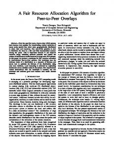
divided by 10 since the samples are taken every 10 frames. Fig. 7, where the number of users is fixed to 20, shows that our algorithms outperform the coverage of BS–Max, which means that with our algorithms, a higher number of users can support a rate ≥ R than in the case without relay. Hence, our algorithms can increase the coverage by increasing the number of supported users. For example, at R = 1 Mbps, the outage probability is reduced by 10% compared to BS-Max, allowing 10% more users to attain a rate higher than 1 Mbps. RS–Max with adaptive time division achieves a slightly better coverage than the fixed algorithm.
0.7 0.6 0.5 0.4 BS−Max RS−Max fixed RS−Max adapt UB
0.3 0.2
3.5
3
Goodput [b/s/Hz]
0.1 0
UB BS−Max RS−Max fixed RS−Max adapt
2
Fig. 7.
3
4 5 Rates [Mbps]
6
7
8
System outage performance
2.5
2
1.5
1
0.5 5
10
15
20
Number of users
Fig. 5.
Cell goodput performance
results showed that our algorithms performed well compared to the upper bound algorithm, with a much lower complexity and required CSI. Even with an increased overhead, our algorithms outperformed the Max C/I algorithm without relay for both goodput and outage. This was not obvious: without an appropriate algorithm design, the gain from the relay could be erased by the loss due to the increased overhead. In a relayed system, we are mostly interested in reducing the outage probability, which was achieved by our algorithms while increasing the overall goodput. As a future work, by combining the proposed algorithms with Proportional Fair Scheduling, the system outage is expected to be further minimized. ACKNOWLEDGMENT
0.7 0.6
We would like to thank Samsung Electronics for supporting this work.
0.5
R EFERENCES
RS−Max adapt
Probability of occurrence
1
0.4 0.3 0.2 0.1 0 0
1
2
3
4 5 6 7 8 9 Length of optimal T in [ms]
10
BS
Fig. 6.
Probability of occurence of different values of TBS
VII. C ONCLUSION In this work, we have proposed practical radio resource algorithms for RS–aided cellular system based on OFDMA technology. After a simple path selection procedure, subchannels are allocated for a fixed time division between BS and RS transmissions, followed by the time adaptation. Simulation
[1] R. Knopp and P. Humblet, “Information capacity and power control in single cell multiuser communications,” in IEEE ICC, Seattle, WA, June 1995. [2] R. Pabst et al., “Relay-Based Deployment Concepts for Wireless and Mobile Broadband Radio,” IEEE Wireless Comm. Mag., pp. 80–89, September 2004. [3] G. Li and H. Liu, “Resource Allocation for OFDMA Relay Networks,” in Thirty-eighth Asilomar Conference on Signals, Systems & Computers, Pacific Grove, CA, November 2004. [4] M. Herdin, “A Chunk Based OFDM Amplify-and-Forward Relaying Scheme for 4G Mobile Radio Systems,” in IEEE ICC, Turkey, June 2006. [5] F.-C. R. et al, “Recommendation on PMP Mode Compatible TDD Frame Structure,” IEEEC802.16MMR-05 027r1, Nov 2005. [6] H. Hu and H. Liu, “Range Extension without Capacity Penalty in Cellular Networks with Digital Fixed Relays,” in IEEE GLOBECOM, Dallas, Texas, December 2004. [7] I-K. Fu et al, “Reverse Link Performance of Relay-based Cellular Systems in Manhattan-like Scenario,” IEEEC802.16MMR-06 004r1, Jan 2006. [8] S. Yoon, et al., “Orthogonal frequency division multiple access with an aggregated sub–channel structure and statistical channel quality measurements,” in Proc. IEEE VTC, vol. 2, Los Angeles, CA, September 2004, pp. 1023–1027.