sun-3 75. 5.5. 1.8. 3.06. IBM RT-APC. 5.9. 2.5. 2.36. VAX 8800. 16.0. 6. 2.67 .... HIPPI (1 Gb/s). Ethernet (10 Mb/s) ... (Ultranet). Supercomputer. Cisco. Router. Visualization. Workstation. Client .... time limit even if the segment is partially empty.
RAID-II: A Scalable Storage Architecture for High-Bandwidth Network File Service Edward K. Lee Peter M. Chen John H. Hartman Ann L. Chervenak Drapeau Ethan L. Miller Randy H. Katz Garth A. Gibson David A. Patterson
Abstract
RAID-II (RAID the second) is a scalable high-bandwidth network le server for heterogeneous computing environments characterized by a mixture of high-bandwidth scienti c, engineering and multi-media applications and low-latency high-transaction-rate UNIX applications. RAID-II is motivated by three observations: applications are becoming more bandwidth intensive, the I/O bandwidth of workstations is decreasing with respect to MIPS, and recent technological developments in high-performance networks and secondary storage systems make it economical to build high-bandwidth network storage systems. Unlike most existing le servers that use a bus as a system backplane, RAID-II achieves scalability by treating the network as the system backplane. RAID-II is notable because it physically separates les service , the management of le metadata, from storage service , the storage and transfer of le data; stripes les over multiple storage servers for improved performance and reliability; provides separate mechanisms for high-bandwidth and low-latency I/O requests; implements a RAID level 5 storage system; and runs LFS, the Log-Structured File System, which is speci cally designed to support high-bandwidth I/O and RAID level 5 storage systems.
Key words: high-bandwidth network le service, network storage, mass storage system, RAID.
1
1 Motivation RAID-II (RAID the second) is a scalable high-bandwidth network le server being developed at the University of California at Berkeley as part of a project to study high performance, large capacity and highly reliable storage systems. RAID-II is designed for the heterogeneous computing environments of the future consisting of diskless supercomputers, visualization workstations, multimedia platforms and UNIX workstations. The primary purpose of RAID-II is to serve as a vehicle for research of storage architectures and le systems for the future. RAID-II incorporates the fruits of two novel research projects. First, as the name of the prototype implies, the storage system is based on RAID [9], the Redundant Arrays of Inexpensive Disk technology developed by the RAID group at Berkeley. RAID replaces large expensive disks with many small inexpensive disks to provide higher performance and reliability at a lower cost. Second, RAID-II will run LFS [10], the Log-Structured File System, developed by the Sprite operating system group at Berkeley. LFS is a le system specially optimized to support high-bandwidth I/O and fast crash recovery. RAID and LFS are synergistic technologies that together obtain far greater performance than when either is used alone. The development of RAID-II is motivated by three key observations. First, we notice a trend toward bandwidth-intensive applications: multi-media, CAD, object-oriented data bases and scienti c visualization. Even in well established application areas such as scienti c computing, reductions in the cost of secondary storage and the introduction of faster supercomputers have caused a rapid growth in the size of datasets, requiring faster I/O systems to transfer the increasing amounts of data. Second, experience with RAID-I [3], our rst prototype, shows that most of today's workstationbased le servers are incapable of supporting high-bandwidth I/O. Moreover, the future I/O performance of server workstations is likely to degrade relative to the overall performance of their client workstations even if applications do not become more I/O intensive. This is because today's workstations achieve high performance by using large fast caches without signi cantly improving the performance of the primary memory and I/O systems. Table 1 is paraphrased from a paper by Ousterhout [8] that discusses why operating system performance is not scaling with microprocessor performance. It illustrates the trend of decreasing memory system performance relative to MIPS in workstations. The third key observation is that recent technological developments in networks and secondary storage systems make it possible to build high-bandwidth supercomputer le servers at workstation prices. Until recently, anyone wishing to build a high-bandwidth supercomputer I/O system had to invest millions of dollars in proprietary high-bandwidth network technology and expensive paralleltransfer disks. But with the standardization of high-performance interconnects and networks such as HIPPI and FDDI, and the commercialization of the RAID technology, high-bandwidth networks and secondary storage systems have suddenly become a�ordable. What is lacking, and the point that RAID-II addresses, is a storage architecture that can exploit these developments. This paper describes RAID-II, a scalable high-bandwidth network le server for heterogeneous computing environments. We focus primarily on the hardware components of the system, although the software is also discussed where relevant. The paper starts with a brief survey of existing le server architectures. The survey is followed by the architecture and implementation of RAID-II. We end the paper with our current status, summary and conclusions. 2
MB/s MicrovaxII 3.3 sun-3/75 5.5 IBM RT-APC 5.9 VAX 8800 16.0 Sun-4/280 5.0 SPARCstation-1 6.9 DECstation 3100 5.4 H-P 9000-835CHX 6.2 DECstation 5000 12.6 MIPS M2000 20.0
MIPS (MB/s)/MIPS 0.9 3.67 1.8 3.06 2.5 2.36 6 2.67 8 0.63 10 0.69 12 0.45 14 0.44 18 0.70 20 1.00
Memory Bandwidth vs. Mips. Throughput for a bcopy procedure when copying a block of data that is much larger than the CPU cache. Note the decreasing trend in (MB/s)/MIPS as MIPS increases.
Table 1:
2 Existing File Server Architectures In this section, we examine several existing le server architectures. The material in this section will serve as a background for the discussion of various aspects of RAID-II in the sections to follow. First we examine RAID-I, a workstation-based le server we modi ed to provide high-bandwidth le service. Next we look at the Auspex NS5000 le server which is highly successful in providing scalable high-performance NFS le service. Finally, we examine several mass storage systems (MSS) currently used by supercomputing centers for high-capacity shared storage.
2.1 RAID-I
RAID-I [3] (RAID the rst) was designed to test the ability of workstation-based le servers to provide access to the high bandwidth and high I/O rates supported by disk arrays. The prototype was constructed using a Sun 4/280 workstation with 128 MB of memory, 28 5 1/4 inch SCSI disks and four dual-string SCSI controllers. Experiments with RAID-I show that it is good at sustaining small random I/O's, performing approximately 300 4 KB random I/Os per second. However, RAID-I has proven woefully inadequate for high-bandwidth I/O, sustaining at best 2.3 MB/s to a user-level application on RAID-I. In comparison, a single disk on RAID-I can sustain 1.3MB/s. There are several reasons why RAID-I is ill-suited for high-bandwidth I/O. The most serious is the memory contention experienced on the Sun 4/280 server during I/O operations. The copy operations performed in moving data between the kernel DMA bu�ers and bu�ers in user space saturate the memory system when I/O bandwidth reaches 2.3MB/s. Second, because all I/O on the Sun 4/280 goes through the CPU's virtually addressed cache, data transfers experience interference from cache ushes. Finally, high-bandwidth performance is limited by the low bandwidth of the Sun 4/280's VME system bus. Although nominally rated at 40 MB/s, the bus becomes saturated at 9 MB/s. The above problems are typical of many "CPU-centric" workstations that are designed for good processor performance but fail to support adequate I/O bandwidth. In such systems, the memory 3
system is designed so that the CPU has the fastest and highest-bandwidth path to memory. For busses or backplanes farther away from the CPU, the available bandwidth to memory drops quickly. This is in sharp contrast to mainframe computers where the memory system is designed speci cally to support high-bandwidth I/O. To summarize, our experience with RAID-I indicates that the memory systems of workstations are in general poorly suited for supporting high-bandwidth I/O. In the design of RAID-II, our second prototype, we have given this careful consideration.
2.2 Auspex NS5000
The Auspex NS5000 [6] is designed for high-performance NFS le service. NFS is the most common network le system protocol for workstation-based computing environments. NFS is designed to e�ciently support operations on small and medium sized les, but because NFS transfers les in small individual packets, it is ine�cient for large les. In the NS5000, the network processing, le system management, and disk control are handled by separate dedicated processors. This functional multiprocessing , in contrast to symmetric multiprocessing, makes synchronization between processes explicit and allows the performance of the le server to easily scale by adding processors, network attachments and disks. This is in contrast to a typical NFS le server that performs all functions on a single processor. In such systems, performance can be scaled to only a very limited degree by adding additional network attachments and disks because the processor will quickly become a bottleneck. Although the NS5000 is good at supporting small low-latency NFS requests, it is unsuitable for high-bandwidth applications. The use of a single 55 MB/s VME bus to connect the networks, disks and memory signi cantly limits the aggregate I/O bandwidth of the system. More importantly, NFS is very ine�cient for large les because it always breaks up les into small packets which are sent individually over the network. This results in fragmentation of the available network bandwidth and forces the receiving system to handle a large number of interrupts.
2.3 Supercomputer Mass Storage Systems
Almost all supercomputer mass storage systems use a mainframe as a high-performance le server. The mainframe maintains the le system metadata, and provides a high-bandwidth data path between its channel-based I/O system and supercomputer clients via a high-performance channel or network interface. Because most supercomputer mass storage systems are designed primarily for capacity, very few support data transfer rates over 10 MB/s. For performance, supercomputer applications rely on directly attached parallel-transfer disks. Supercomputer mass storage systems also are not designed to service a large number of small le requests, and are rarely used as primary storage systems for large numbers of client workstations. The following brie y describes the MSS-II, NCAR and LSS mass storage systems. MSS-II [11], the NASA Ames mass storage system, uses an Amdahl 5880 as a le server. MSS-II achieves data transfer rates up to 10 MB/s by striping data over multiple disks and transferring data over multiple network channels. The mass storage system at NCAR [7], the National Center for Atmospheric Research, is implemented using Hyperchannel and an IBM mainframe running MVS. The NCAR mass storage system is unique in that it provides a direct data path between supercomputers and the IBM main4
frame's channel-based storage controllers. On a le access, data can bypass the mainframe and be transferred directly between the storage devices and the supercomputers. The Lawrence Livermore National Laboratory's LINCS Storage System (LSS) [5], is closely modeled after the Mass Storage System (MSS) Reference Model. The (MSS) Reference Model [4] identi es and de nes the function and software interfaces for six elements of a mass storage system: name server, bit le client, bit le server, storage server, physical volume repository and bit le mover. A client le access in LSS begins at the name server, which maps a human readable name to a bit le ID. The bit le server uses the bit le ID to perform authentication checks and maintain/lookup metadata related the le, such as the logical volume and bitstream o�sets at which the bit le is stored on the storage server. The storage server maps the logical volume and bitstream o�sets to physical device and block o�sets and retrieves the requested data. If the data is stored on an unmounted storage media, the physical volume repository is instructed to mount the media. The bit le mover then transfers the data between the storage server and the client. A notable aspect of LSS is that control and data messages are always transmitted independently. This allows the control and data messages to take di�erent paths through the system. For example, a control message requesting a write would be sent to the bit le server but the data itself would be sent directly to the storage server, bypassing the bit le server. This is e�cient for large data transfers but the extra overhead of treating control and data independently is likely to degrade the performance of small NFS-type requests.
2.4 Summary
We have examined the architecture of several existing le servers and discussed why they are unsuitable for heterogeneous computing environments consisting of both high-bandwidth data transfers and high-transaction rate NFS-type requests. As RAID-I illustrates, the relatively low performance of workstation memory systems make them unsuitable for use as high-bandwidth le servers. Not surprisingly, specially designed le servers such as the Auspex NS5000, while supporting large numbers of NFS clients, provide only marginal performance for high-bandwidth clients. Although most supercomputer mass storage systems can transfer data at relatively high rates of up to 10 MB/s, this is still not good enough to support diskless supercomputers. Furthermore, they neglect the performance of small NFS-type requests in order to optimize the performance of highbandwidth data transfers. Finally, even if the supercomputer mass storage systems were optimized to support NFS-type requests, it would be economically infeasible to use mainframes as le servers for workstations. In the following sections, we describe the architecture and implementation of RAID-II and how it economically supports both high-bandwidth data transfers and low-latency high-transaction-rate NFS-type requests.
3 RAID-II Storage Architecture Architecturally, RAID-II resembles the previously described LSS mass storage system and roughly follows the structure of the Mass Storage System Reference Model. RAID-II, however, is distinctive in its attention to low-latency high-transaction-rate NFS-type requests characteristic of UNIX client workstation. It is a speci c design goal of RAID-II to service NFS-type requests as well as, if not better than, today's workstation-based le servers. Thus, the design of RAID-II is driven by very di�erent motivations than the design of supercomputer mass storage systems. We think 5
of RAID-II as more of an evolution of workstation-based le servers than supercomputer mass storage systems. Even without supercomputers, architectures like RAID-II are needed due to the rapid trend in workstation-based computing environments toward larger datasets and bandwidth intensive applications. Section 4 explains the reasoning which lead us to the RAID-II Storage Architecture and brie y describes the architecture. Sections 4.1 and 4.2 describes the hardware (structural) and software (functional) aspects of the two main components of the RAID-II Storage Architecture: the RAID-II storage server and the RAID-II le server. Finally, Section 4.3 describes an innovative le system called the Log-Structured File System which runs on the RAID-II le server, and without which the performance of RAID-II would be no better than the average workstation-based le server.
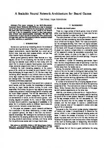
4 Network as Backplane Today, high-bandwidth le service for supercomputers is provided by mainframe computers. Unfortunately, it is highly ine�cient to use mainframes to provide NFS le service for a large number of client workstations. NFS le service is a highly CPU intensive task for which mainframes have little advantage over RISC workstations and which would leave the expensive high-bandwidth I/O systems of mainframes virtually unutilized. Unfortunately, the other alternative, using workstationbased le servers to serve both workstation and supercomputer clients is even worse. As our experiences with RAID-I strongly point out, workstations are unlikely to support high-bandwidth I/O in the near future. Ideally, we would like to combine the high-bandwidth I/O systems of mainframes with the inexpensive computing power of RISC workstations. Moreover, we would like to be able to independently scale the bandwidth and CPU power of the network le server to accommodate a wide range of supercomputer and NFS type workloads. Clearly a exible interconnection scheme that could scale in both bandwidth and the number of attached components is the key to solving the above problems. With this in mind, we considered a wide array of bus-based and bit-sliced server architectures. Unfortunately, all of the architectures we considered required large amounts of specialized hardware. In the end, however, the solution was staring us in the face; the network itself is the most exible and general interconnect . RAID-II is radically di�erent from conventional workstation-based network le servers. These use a bus as the primary system backplane between the network, secondary storage system and CPU whereas RAID-II uses the network as the primary system backplane. Instead of connecting the high-bandwidth secondary storage system to the high-bandwidth network via a low-bandwidth bus, we connect it directly to the high-bandwidth network and refer to it as the RAID-II storage server. Similarly, the CPU, now referred to as the RAID-II le server, is also connected to the network. The result is a high-performance storage system that is more scalable than conventional network le servers in much the same way networks are more scalable than busses. Figure 1 illustrates the RAID-II storage architecture. A variety of clients from supercomputers to desktop workstations, RAID-II storage servers and RAID-II le servers are interconnected over a network composed of high-bandwidth network switches, FDDI networks, Ethernets and network routers.
6
Visualization
Client
Client
Client
Workstation
Workstation
Workstation
Workstation
Supercomputer
Ethernet (10 Mb/s)
High Bandwidth Cisco Network Switch Router (Ultranet)
HIPPI (1 Gb/s) FDDI (100 Mb/s)
RAID-II
RAID-II
RAID-II
RAID-II
Client
Storage Server
Storage Server
File Server
File Server
Workstation
Figure 1:
RAID-II Storage Architecture.
4.1 Storage and File Servers: Independence and Interdependence
As mentioned in the previous section, the RAID-II storage server corresponds to the secondary storage system of conventional network le servers. As such, the RAID-II storage server implements a logical device-level interface and loosely corresponds to the de nition of storage server given in the MSS Reference Model. Storage on the RAID-II storage server is addressed using a logical device name and o�set within the device. The RAID-II storage server is implemented with custom hardware and software. The RAID-II le server combines the functionality of the MSS Reference Model's name server and bit le server. In particular, it translates hierarchical human-readable le names to logical device addresses for use by the RAID-II storage server, manages the metadata associated with each le, and provides a cache of recently accessed les. The RAID-II le server is an o�-the-shelf RISC workstation running the Log-Structured File System. Separating the RAID-II storage system into storage servers and le servers has several advantages. If we need additional I/O bandwidth, we simply add more storage servers without a�ecting the number of le servers. If we nd the le servers overutilized, we can add more le servers without adding more storage servers. To some extent adding storage servers is like adding disks to a conventional le server but an important distinction is that when you add a storage server, you increase the I/O bandwidth available to the network whereas when you add a disk you only increase the I/O bandwidth available to the given le servers, whose backplane, if the le server is a typical workstation, is easily saturated. Additionally, we can increase data transfer bandwidth for servicing individual I/O requests by 7
striping les over multiple storage servers. That is, we can build a le system on a logical disk spanning multiple storage servers. Striping over multiple storage servers is also useful for load balancing. Note that striping over multiple storage servers is conceptually simple|we can treat it similarly to disk striping|because synchronization and logical le operations for a given le are still handled by a single le server. Being able to scale by striping data over multiple storage servers is important for several reasons. First, when designing a shared storage system for a heterogeneous environment, it is uneconomical to build a storage server capable of supplying the full I/O bandwidth of the fastest supercomputer client. The storage server's capabilities would be wasted on the majority of clients, which are desktop workstations. Second, even if one built such a super storage server, it would quickly become inadequate when the next generation of supercomputers becomes available. Clearly a storage architecture whose bandwidth for individual requests is incrementally scalable is highly desirable. Another advantage of physically separating the storage and le servers is apparent when one considers redundancy schemes designed to tolerate server failures. It is easy to implement di�erent redundancy schemes to protect storage servers in comparison to le servers, since they are physically separated. For example, since storage capacity is very important for storage servers, we can use a parity storage server, similar to a parity disk in RAID, to provide access to the contents of a failed storage server. By computing the parity over a large number of storage servers, we can make the storage cost of parity arbitrarily small. On the other hand, we can use simpler higher-performance redundancy schemes such as mirroring or logging to a backup le server to protect le servers from failures, where the storage cost for redundancy is less because there is less state to maintain. Finally, since the storage servers interface directly to the network, it is easy to distribute the storage servers over a wide geographic area to protect against natural disasters such as earthquakes and
oods. On the negative side, separating the storage and le servers increases the overhead to access the storage system. For large high-bandwidth requests, however, the overhead is dwarfed by the data transfer time. We also feel that small requests will not be signi cantly hurt because most small read requests can be e�ciently cached [1] and LFS performs writes asynchronously in the background.
4.2 Standard and High-Bandwidth Modes
In the previous section, we considered several advantages and a disadvantage of the RAID-II hardware architecture. However, the software mechanisms by which requests are serviced has not yet been described. It is evident at this point that the RAID-II hardware architecture can provide scalable high-bandwidth le service, but it is not clear if the software can e�ectively utilize the hardware. In particular, the RAID-II software must e�ciently support both standard low-latency requests and high-bandwidth data transfers. We de ne low-latency requests as small data transfers and le system operations such as open, close and fstat while high-bandwidth requests are de ned as large data transfers. Low-latency requests and high-bandwidth requests obviously have widely di�erent performance characteristics. The performance of low-latency requests is determined primarily by xed network and software overheads. The time spent transferring data is not as signi cant. In contrast, high-bandwidth requests spend most of their time transferring data and are insensitive to xed overheads in the 8
network or software. Thus, it is unlikely that a network protocol that works well for low-latency requests would work well for high-bandwidth requests and visa versa. Low-latency requests are best handled using protocols with small xed software overheads that reduce the number of round-trip messages between clients and servers. In contrast, high-bandwidth requests are best serviced using the highest bandwidth network protocols, even if they require more overhead to setup the data transfers. RAID-II services low-latency requests in standard mode. In standard mode, data and control messages are combined and transmitted together to reduce the number of network messages and software overheads. On reads, the le server returns the data with the acknowledgement and on writes, the client sends the data with the write request. For most reads, a client's request will be satis ed from the le server's cache, resulting in low-latency accesses. When a miss occurs, the le server treats the storage server as a locally attached disk. The requested data is transferred from the storage server to the le server's cache and from there to the client. The scenario is exactly the same as for conventional workstation-based le servers except that the disks are attached to the network rather than the le server's private backplane. In contrast to the standard mode, the high-bandwidth mode is optimized for large data transfers. In high-bandwidth mode, the le server processes each data request by setting up data transfers directly between the storage servers and client. The data completely bypasses the low-bandwidth le server. In addition, high-bandwidth accesses use a connection-based protocol between the client and the storage servers. Typical network le systems use a connectionless protocol that breaks up data into many small packets sent individually over the network. Each packet contains a protocol header specifying the le and le o�set to which it corresponds. For each packet, the recipient takes an interrupt, processes the header and reassembles the contents of the packet. For large high-bandwidth transfers, this results in high processing overhead. The UltraNet, for example, has a maximum packet size of 32KB. To sustain a data rate of 100 MB/s, the recipient of the data must be able to process over 3000 packets per second. The connection-based approach, on the other hand, results in signi cantly less processing overhead. When a client requests a high-bandwidth data transfer, the le server rst performs some preliminary processing to prepare for the transfer. Then it creates a connection between the storage servers and client. Once the connection is established, the client transfers data by issuing read and write requests on the connection. Each request consists of only le data; headers are not needed since the le and le o�set are implicit in the connection. The connection abstraction is easily supported by the storage server's network interface, so that the server workstation need only be noti ed when the entire data transfer is complete. A common problem in designing systems to support two very di�erent types of requests is interference between the two request types. Large high-bandwidth requests should not block the service of low-latency requests and small low-latency requests should not waste the bandwidth available on the high-bandwidth network. Our solution is to provide each RAID-II storage server with both a high-bandwidth 1 Gb/s HIPPI interface and a low-latency 100Mb/s FDDI interface. Each storage server is fully functional with only one of the two network connections, and either request type may use either network, but performance is enhanced if low-latency requests use the FDDI network and high-bandwidth requests use the HIPPI network.
9
4.3 Log-Structured File System
Even with custom hardware and special network protocols, RAID-II could not support highbandwidth data transfers and high-transaction-rate NFS-type le requests without the Log-Structured File System (LFS) [10]. Standard UNIX le systems cannot support high-bandwidth I/O because they store les in small xed-size blocks that often end up scattered over a disk. Also, because we are implementing a RAID level 5 storage system, we are concerned with the throughput and latency for small writes, which are ine�cient in RAID level 5 systems because each small write results in four disk accesses. Two disk accesses are needed to read the old data and old parity followed by two accesses to write the new data and new parity. Standard UNIX le systems, which perform many small synchronous writes, would greatly degrade the performance of RAID-II. LFS, developed by the Sprite operating system group at Berkeley, solves the above problems by laying out data in large contiguous segments and grouping small write requests together. More generally, LFS always appends new data, and the corresponding metadata, in large sequential segments at the end of a log. Small writes are grouped and bu�ered in main memory until enough data to ll a log segment are accumulated. In practice, segments are forced to disk after a certain time limit even if the segment is partially empty. As disk space lls up, segments that become partially empty due to the deletion or overwriting of existing les are garbage collected. An added bonus of LFS is that crash recovery is very quick because data is always written sequentially in a log-like fashion. It takes less than a second to perform an LFS le system check, compared with approximately 20 minutes to check the consistency of a UNIX le system.
4.4 Summary
The RAID-II storage system treats the network as the primary system backplane that interconnects the storage servers, le servers and clients. The physical separation of storage and le servers allows great exibility in con guring the storage system to meet a wide range of performance requirements. The separation of storage and le servers also makes it easy to scale peak data transfer rates to clients by striping data over multiple storage servers. In addition to the method for striping data described in this section, we are also investigating several alternatives. One of the alternatives is similar to that used in Swift [2]. In Swift, the le servers are contacted only when les are opened and closed. Clients perform individual read and write requests directly with the storage servers. This can result in lower-latency le accesses and a reduction in le server load in exchange for a more complex storage server. Unfortunately, the separation of storage and le servers increases the overhead to access physical storage. However, this increased overhead is insigni cant for large transfers. For small data transfers, our recent study [1] indicates that caches combined with asynchronous writes will e�ectively mask the additional overhead for most applications. The RAID-II storage system supports low-latency and high-bandwidth requests by providing the standard and high-bandwidth modes of access, respectively. During the servicing of highbandwidth data requests, data are transferred directly to the high-bandwidth client and bypass the low-bandwidth le server. Providing separate networks for servicing low-latency and highbandwidth requests allows the bandwidth of the high-bandwidth network to be e�ciently utilized and prevents large high-bandwidth requests from blocking small low-latency requests. Finally, RAID-II will run LFS which is optimized to support large high-bandwidth data transfers and RAID level 5 storage systems. 10
5 RAID-II Storage Server The RAID-II storage server is based on a chassis from TMC (Thinking Machines Corporation) and is designed to provide a high-bandwidth path between the secondary storage system and the network. Figure 2 illustrates the RAID-II storage server architecture. The storage server's backplane consists of two high-bandwidth data busses and a low-latency VME control bus. We have adopted the technique of separate paths for high-bandwidth data transfers and low-latency control accesses here as well as in the RAID-II Storage Architecture. The backplane interconnects the HIPPI network interfaces, up to four RAID controllers and a server workstation that controls the operation of the storage server. Note that the system does not contain centralized memory modules. Instead, large data bu�ers are associated with each RAID controller. With centralized memory modules, data would be transferred over the high-bandwidth busses at least twice, once in to and once out of the memory modules. With distributed bu�ers, data is transferred only once over the high-bandwidth busses. Additional transfers are performed locally within the RAID controllers over local busses as needed. An implication of the distributed bu�ers is that on writes, the server must know which RAID controller to send the data to as it is received from the network. In our case, this is easily determined because the storage server implements a logical block-level interface with a simple one-to-one mapping between logical block addresses and physical disk blocks. Architecturally, the RAID-II storage server is very similar to the Maximum Strategy HIPPI-2 Array Controller, which also uses a high-bandwidth (250 MB/s) data bus, a low-latency VME control bus and distributed bu�ers. The performance goal of the RAID-II storage server is to sustain 160 MB/s data transfers, 80 MB/s over each of the two unidirectional HIPPI interfaces. Although each HIPPI interface can transfer data between the network and its TMC-HIPPI bus at close to 100 MB/s, each RAID controller can only sustain 40 MB/s on each of the two TMC-HIPPI busses. To fully utilize the bandwidth supported by the HIPPI interfaces, data is striped over multiple RAID controllers. The VME I/O busses of the RAID controller, are primarily used to interface to ATC (Array Technology Corporation) Array Controllers, although, as Figure 2 illustrates, other VME-based products, such as data compression hardware, can be attached as well. Each VME I/O bus is nominally rated at 40 MB/s, but in practice, it is di�cult to sustain more than 20 MB/s over a VME bus; thus, there are four VME I/O busses per RAID controller to sustain 80 MB/s. The RAID controller is described in more detail in a later section. Figure 3 illustrates the nal physical packaging of the RAID-II storage server under construction, and closely resembles the enclosed photograph which pictures the components so far assembled. The main rack is composed of the TMC chassis containing the HIPPI interfaces and two RAID controllers; a VME chassis containing eight ATC controllers; and a VME chassis containing the server workstation. Two secondary racks will contain a 144 3 1/2 inch 320 MB SCSI disks for a total capacity of 46 GB. In each rack, the disks are arranged on eight shelves with nine disks per shelf.
6 RAID-II I/O Controller The RAID controller interfaces standard VME-based peripherals to the high-bandwidth data busses inside the RAID-II storage servers. It also provides an XOR/DMA engine for performing parity computations in support of RAID secondary storage systems. The RAID controller is the only 11
HIPPI (1 Gb/s)
HIPPI (1 Gb/s)
FDDI (10 Mb/s)
HIPPIS
HIPPID
Server
Interface
Interface
Workstation
TMC-HIPPIS Bus (64-bits, 100MB/s)
TMC-HIPPID Bus (64-bits, 100MB/s)
TMC-VME Bus (32-bits, 40 MB/s)
RAID
RAID
RAID
RAID
Controller
Controller
Controller
Controller
VME0
VME2 VME1
VME4 VME3
VME6 VME5
VME8 VME7
VME10 VME9
ler
VME12 VME11
Data Compression
ler ler ATC Array Controller SCSI19 SCSI14 SCSI9 SCSI0
SCSI1
SCSI2
SCSI3
Figure 2:
SCSI4
RAID-II Storage Server Architecture.
12
VME14 VME13
VME15
VME Chassis
ATC Controllers
TMC Chassis
Power Supplies
Power Supplies HIPPI Interfaces
RAID Controllers
Power Supplies
VME Chassis Power Supplies
Power Supplies
Server Workstation
Figure 3:
RAID-II Storage Server.
major piece of hardware that we ourselves designed and constructed. The other components were obtained from our industrial sponsors. Figure 4 is a block diagram of the RAID controller. Eight independent memory modules, collectively comprising the 128 MB bu�er memory, are connected via the X-Bus, a crossbar-based interconnect, to eight 32-bit 40 MB/s X-Bus ports. The TMC-VME port, in addition to supporting access to the bu�er memory, implements registers for con guring and controlling all components of the RAID controller. In the following sections, we present the rationale for chosing the X-Bus and the speci cations of the X-Bus.
6.1 An Alternative to the X-Bus
Before deciding upon the X-Bus, we carefully considered using a single bus-based interconnect. The main attraction of the bus-based interconnect was its conceptual simplicity. However, because we had neither the experience nor resources to use anything other than TTL/CMOS technology, we were limited to a bus cycle time of approximately 80 ns. To sustain 40 MB/s over each of the two HIPPI ports (40 MB/s of reads and 40 MB/s of writes), we need a bus bandwidth of 200 MB/s. That is, 80 MB/s for the reads (40MB/s into and 40 MB/s out of memory) and 120 MB/s for writes (same as for reads + 40 MB/s to compute the parity). Since we cannot realistically expect to achieve a bus utilization greater than 70-80 percent, this implied that the bus would have to be 256-bits wide with a peak bandwidth of 400 MB/s. Unfortunately, the number of fo and transceiver chips required to implement each 256-bit bus 13
MEM
32 40 MB/s
MEM
MEM
MEM
MEM
MEM
MEM
MEM
32
32
32
32
32
32
32
32
32
32
32
X-BUS 32 40 MB/s
HPPIS
32
32
HPPID
32
TMC-VME
VME0
VME1
VME2
VME3
PORT
PORT
PORT
PORT
PORT
XOR/DMA PORT
64 100 MB/s TMC-HIPPIS
PORT
64 100 MB/s TMC-HIPPID
32 40 MB/s TMC-VME
Figure 4:
32 40 MB/s VME0
32 40 MB/s VME1
32 40 MB/s VME2
32 40 MB/s VME3
RAID-II I/O Controller.
port was astronomical. A solution was to use a small number of time-multiplexed 256-bit ports interfaced to narrower 32-bit and 64-bit busses. The result was a complex system of interconnected busses of di�ering widths. Eventually, the 256-bit bus was abandoned in favor of a crossbar-based interconnection scheme that we call the X-Bus.
6.2 The X-Bus
The X-bus is a synchronous multiplexed (address/data) crossbar-based interconnect that uses a centralized strict priority-based arbitration scheme. All paths to memory can be recon gured on a cycle-by-cycle basis. Each of the eight 32-bit X-bus ports operates at a cycle time of 80 ns, providing a peak bandwidth per port of 50 MB/s and an aggregate peak memory bandwidth of 400 MB/s. The memory is interleaved in sixteen-word blocks to allow block transfers to use the faster page mode of DRAM chips. Each X-bus port must rearbitrate when crossing memory module boundaries. The X-Bus supports only two types of bus transactions: reads and writes. During each XBus transaction, 1 to 16 words are transferred over the X-Bus. Each transaction consists of an arbitration phase, an address phase, and a data phase. If there is no contention for memory, the arbitration and address phases each take a single cycle; data is then transferred at the rate of one word per cycle. The memory may arbitrarily insert wait cycles during the address and data cycles to compensate for DRAM access latencies and refreshes. The shortest X-Bus transaction is a single word write, which takes three cycles, one each for the arbitration, address and data phases. An important concern with the X-Bus is contention for memory modules. In practice, contention 14
is infrequent because most X-Bus ports perform large sequential accesses. When X-Bus ports con ict, the loser of the arbitration ends up following the winner around the memory modules in a deterministic manner, avoiding further con icts. Also, each X-Bus port can bu�er at least a kilobyte of data to/from the X-Bus to even out uctuations caused by memory con icts. Detailed board level simulations under extreme workloads indicate that contention for memory modules is not a signi cant problem. Note that because the VME ports can realistically sustain only 20 MB/s, the maximum utilization of the X-Bus is approximately 65%.
6.3 Summary
The main advantage of the crossbar-based memory system is that high aggregate memory bandwidth is made available using relatively inexpensive 32-bit ports. One disadvantage is that a single port cannot utilize the full 400 MB/s of memory bandwidth as in the wide-bus memory system but is limited to 40 MB/s. In our case, this is not a serious problem since only the HIPPI ports could have sustained more than 40 MB/s. Another disadvantage is that, although the ports are inexpensive, the crossbar itself is expensive. We implemented the crossbar using 192 16-bit transceivers. Using surface mount packaging we are able to implement the crossbar in 120 square inches or approximately 20 % of the RAID controller's board area.
7 Status As of the writing of this paper, most of the hardware components of RAID-II have been assembled. We are primarily awaiting the fabrication of the RAID controller boards which should be nished in the next two months. In terms of software, LFS has been in production use for the past year and the software for implementing RAID secondary storage systems has been in experimental use for the past six months. Zebra, the network le system software for striping les over multiple storage servers, is currently under research and development. If all goes according to plan, RAID-II should be available for experimental use in the next four to six months. Once our experiments with RAIDII are complete, it will be sent to NASA Ames for experimental use and, possibly, integration into the MSS-II storage system.
8 Summary and Conclusions The RAID-II Storage Architecture is motivated by three observations: applications are becoming more bandwidth intensive, the I/O bandwidth of workstations is decreasing with respect to MIPS, and recent technological developments in high performance networks and secondary storage systems make it economical to build high-bandwidth network storage systems. Most existing high-bandwidth network storage systems have been designed primarily to provide shared long-term storage for supercomputers. The relatively low bandwidth (approximately 10 MB/s) of existing network storage systems makes it necessary to use privately attached parallel-transfer disks for running most supercomputing applications. RAID-II shares many things in common with existing mass storage systems such as bypassing the le server on high-bandwidth accesses by using separate paths for data and control as in the NCAR and LSS mass storage systems. However, because RAID-II is designed from the point of view of extending current workstation network storage systems to provide high-bandwidth network 15
le service rather than speci cally as a storage system for supercomputers, it pays much greater attention to small low-latency NFS-type requests. For example, we minimize the number of network messages needed to perform small data transfers by combining data and control messages as in existing workstation-based network le systems. This is in contrast to LSS which always separates data and control, which for small requests, results in a signi cantly larger number of network messages and higher latencies. Another example is the RAID le server's le cache. While le caches are common in workstation-based le servers, most supercomputer storage systems do not support le caches because of the large size of le transfers. The distinctive features of the RAID-II Storage Architecture are as follows: � While conventional network le servers use a bus as the primary system backplane between the network, secondary storage system and CPU, RAID-II uses the network as the primary system backplane. This allows RAID-II to scale in performance as network performance scales. � RAID-II separates the storage system into storage servers and le servers to gain exibility in con guring the storage system to meet a wide range of performance and reliability requirements. � RAID-II stripes les over multiple storage servers to achieve higher-bandwidth data transfers. The striping is conceptually simple and can be handled similarly to disk striping because, for each le, there is only one le server that is responsible for its consistency. � RAID-II provides both a standard mode of le access and a high-bandwidth mode of le access for large les. In the high-bandwidth mode of access, data bypass the low-bandwidth le server and are transferred directly between the storage servers and client. The distinctive implementation features of RAID-II are as follows: � RAID-II runs LFS, the Log-Structured File System, which lays out les in large contiguous segments to provide high-bandwidth access to large les, groups small write requests into large write requests and provides fast crash recovery. � The RAID-II storage server uses two high-bandwidth busses each capable of sustaining 80 MB/s for data transfers and a low-latency VME bus for control. Furthermore, the storage server implements distributed bu�ers rather than a centralized bu�er to reduce data transfers over the high-bandwidth busses. � The RAID controller uses an 8 � 8 crossbar-based interconnect with a peak bandwidth of 400 MB/s instead of a single wide bus. In closing, we would like to say that over the course of designing and implementing RAID-II, our project gradually evolved from focusing on only secondary storage systems to investigating highperformance network le servers. In trying to use the systems we build, we came to realize that existing storage architectures cannot take full advantage of low-cost high-performance secondary storage systems. We feel that the main concepts of the RAID-II Storage Architecture will be as signi cant for high-bandwidth network storage systems as the concepts in RAID, Redundant Arrays of Inexpensive Disks, have been for secondary storage systems. In fact, the RAID-II Storage Architecture incorporates many of the successful concepts from RAID. 16
9 Acknowledgments We would like to thank the other members of the RAID and Sprite groups at Berkeley for their contributions to RAID-II. In particular we would like to thank Joel Fine, Ken Lutz, John Ousterhout, Rob P le, Mendel Rosenblum, Srinivasan Seshan, Ken Shirri�, and Mani Varadarajan. This research was supported by Array Technologies, DARPA/NASA (NAG2-591), DEC, HewlettPackard, IBM, Intel Scienti c Computers, California MICRO, NSF (MIP 8715235), Seagate, Storage Tek, Sun Microsystems and Thinking Machines Corporation.
17
References [1] Mary G. Baker, John H. Hartman, Michael D. Kupfer, Ken W. Shirri�, and John K. Ousterhout. Measurements of a distributed le system. In Proc. ACM Symposium on Operating Systems Principles, volume 25, pages 198{212, October 1991. [2] Luis-Felipe Cabrera and Darrell D. E. Long. Swift: A storage architecture for very large objects. Technical Report RJ 7128 (67375), IBM Research Division, Almaden Research Center, San Jose, California 95120-6099, November 1989. [3] Ann L. Chervenak and Randy H. Katz. Performance of a disk array prototype. In Proc. SIGMETRICS, pages 188{197, May 1991. [4] Sam Coleman and Steve Miller. Mass Storage System Reference Model: Version 4 (May, 1990). IEEE Technical Committee on Mass Storage Systems and Technology, May 1990. [5] Joy Foglesong, George Richmond, Loellyn Cassel, Carole Hogan, John Kordas, and Michael Nemanic. The Livermore distributed storage: Implementation and experiences. Technical Report UCRL-102663, Lawrence Livermore National Laboratory, May 1990. [6] Bruce Nelson. An overview of functional multiprocessing for NFS network servers. Technical Report Technical Report 1, Auspex Engineering, 1990. [7] Mare Nelson, David L. Kitta, John H. Merrill, and Gene Harano. The NCAR mass storage system. In Proc. IEEE Symposium on Mass Storage Systems, pages 12{20, November 1987. [8] John K. Ousterhout. Why aren't operating systems getting faster as fast as hardware. In Proc. USENIX Technical Conference, pages 247{256, June 1990. [9] David A. Patterson, Garth Gibson, and Randy H. Katz. A case for redundant arrays of inexpensive disks (RAID). In Proc. ACM SIGMOD, pages 109{116, June 1988. [10] Mendel Rosenblum and John Ousterhout. The design and implementation of a log-structured le system. In Proc. ACM Symposium on Operating Systems Principles, pages 1{15, October 1991. [11] David Tweten. Hiding mass storage under Unix: NASA's MSS-II architecture. In Proc. IEEE Symposium on Mass Storage Systems, pages 140{145, May 1990.
18