Rainbow Cube Assembly Guide. 1.8mm RGB LED x70. 4.Side A slim PCB X4. 7.
2.54mm 40pin femail header. X2. 10.8pin female header X5. 2.Cube Panel X1.
Rainbow Cube Assembly Guide
1.8mm RGB LED x70
2.Cube Panel X1
3.Slim Panel PCB X4
4.Side A slim PCB X4
5.Side B slim PCB X4
6.2.54mm 40pin male header X5
7.2.54mm 40pin femail header
8.2.54mm 16pin female header
9.2.0mm 10pin female header X2
X2
X3
10.8p in female header X5
11.2X3 female header X1
12.JST power cab le X1
13.3.5mm 4pin g reen terminal X1 14.3.5mm DC jack X1
15.3mm LED red X1
16.3mm LED green X1
17.1K 1/8w resistor X4
18.10k 1/8w resistor X1
19.15k 1/8w resistor X1
20. linear voltage regulator X1
21.10uF_16v_ E-CAP X2
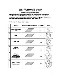
Before starting build your cube, please read though all the instructions first. Bulding the Cube is not difficult, but it will take your about 90 minutes to finish it.
Building the Cube. LED Soldering
Find the bag included 70 RGB LEDs and 4 Slim Panel PCBs, hold one LED, lines up the pins and push it in. The longest pin of LED needs to lines up to the square though hole on PCB,(Marked red). Notice the flat spots about 5mm away from the LED, stop pushing the LED in when the flat spots reached the PCB. Please note that the LED pins need to line up to silk screen.
Repeat doing this, fill all 4 slim panel PCBs with LEDs, solder them and clip off
the extra wires. Tips: It's recommended to set the iron temperature at 350 centi degree, or you might burn the LEDs. Side A slim PCB
In this part we need the Side A slim PCBs. (PCB in stick shape marked Side A). Now we need to solder it to the Slim panel PCB. There's 4 of each, pick-up one randomly and find the 'Side A' silk screen and notch on both PCBs, connect them with the north and solder them together. please notice the angle needs to be at 90 degree.
Do this again, solder the rest 3 Side A slim PCBs to the Slim Panel PCB.
Slim Panel PCB
Now we should have 3 Slim Panel PCBs left, line them up to the same direction of the already soldered Slim Panel PCB, connect Slim Panel PCBs to Side A slim PCBs with the notch and solder them. Now you will find your cube is almost there, take a break and go on. Side B slim PCB
In this part we will solder 4 side B slim PCBs to the cube, pickup one randomly, find the Side B silk screen and the north on both PCBs. Connect them with the notch and solder them together. Please note that the 'side B' silk screen on Slim Panel PCBs look a bit like 'Side R', we will try fix this problem in the next version.
Side A and Side B soldered Do this again, solder the rest 3 Side B slim PCBs to the cube.
Jumper Pad
To make this cube work correctly, we need to solder 8 jumper pads on Side A and B slim PCBs.
Side A Flip the cube, let the Side A PCBs line up to you, Find the position of 4 SMD jumper on this side (Marked in above pic), solder them. Please do make any mistake on this step or the cube will not working correctly.
Side B Flip the Cube again and let Side B slim PCBs line up to you. Find the other 4 jumper pads and solder them. The position are slightly different than those on Side A, please note this.
Cube Panel Soldering Soldering the Cube panel is pretty easy,
The PCB is all though hole so it won't take
you much time. Xbee headers (Optional)
This step is optional, do it if you want use Xbee socket compatible module with your cube. Find the 2.0mm 10pin female header provided in kit, solder them to the place marked Xbee. Resistors
Find the 6 resistors included in kit, bend the pins of the resistor at 90 degree
angels as close as possible to the body of it. Insert them into the space marked R1-R6. Orientation is really not important, solder them and clip of the extra wires. Please note that there are 3 different values of resistor provided, you should be able to find the corresponding values on silk screen. Don't make mistake or the cube will not working correctly. Status LEDs
Find 3mm green LED and red LED, Solder them in place. Please note that the
Longest pin needs to line up the square though hole. Flip the PCB, solder them and trim the excess pins. Powe r Jack
Solder the DC power jack into the space labeled DC in. Make sure to fill in the three holes entirely to make a good solid connection. Regulator
Solder the regulator into the space labeled 1117-3.3 TO 220. Terminal
Solder the Terminal into the space labeled J1, the metal pins should line up the silk screen. Capacitor
Insert 2 capacitor to the space labeled C1 C2, the longer pin should line up the square hole. Flip the PCB, solder them and trim the excess pins. Pin-heade rs for Rainbowduino
In this part you will need 40pin male header, find them and divide it into 2 16pin male headers, insert and solder them on cube panel as picture shown.
Putting them together
Now we should have 1 X assembled cube panel and 1 X assembled rainbow cube. Simply connect and solder them. You will find the corresponding silk screen on each board,
Final Step
The cube is now successfully built! Before light it up, we need to connect the power cable to the terminal and connect the cable to Rainbowduino. Rainbowduino will directly fetch power from the terminal of Cube Panel. Now you can mount Rainbowduino on Cube panel, Power it and enjoy the lighting!
Thanks for purchasing from us!