Electrical Power and Energy Systems 96 (2018) 296–305
Contents lists available at ScienceDirect
Electrical Power and Energy Systems journal homepage: www.elsevier.com/locate/ijepes
Ramp-rate control approach based on dynamic smoothing parameter to mitigate solar PV output fluctuations
MARK
⁎
Shivashankar Sukumara, Hazlie Mokhlisb, , Saad Mekhilefb, M. Karimic,d, Safdar Razae a
Institute of Power Engineering (IPE), Universiti Tenaga Nasional, 43000, Malaysia Department of Electrical Engineering, University of Malaya, 50603 Kuala Lumpur, Malaysia c Department of Electrical Engineering, Faculty of Basic Sciences and Engineering, University of Gonbad Kavous, Iran d School of Electrical and Electronics Engineering, The University of Manchester, United Kingdom e Department of Electrical Engineering, NFC IET, Multan, Pakistan b
A R T I C L E I N F O
A B S T R A C T
Keywords: Energy storage PV smoothing Ramp-rate control Solar PV
In this paper a new ramp-rate control strategy based on exponential smoothing (ES) method is proposed. Different from conventional ES, the proposed method varies the smoothing parameter ‘σ’ according to PV ramprate. The proposed smoothing parameter is used to determine the switching status of the battery energy storage (BES). It is also used in determining the amount of power to be injected or absorbed by the BES in order to smooth the PV output power. The proposed ramp-rate control strategy is compared with moving average (MA) and conventional exponential smoothing (CES) methods. It has been found that MA and CES method exhibit memory effect that caused BES to operate all the time. The proposed ramp-rate control strategy overcomes this limitation by operating the BES only during significant fluctuation. As a result, the size of the BES capacity can be reduced and increasing its life span.
1. Introduction Output power generated from solar photovoltaic (PV) is variable in nature, due to frequent change in solar radiation level caused by cloud passing. Mitigating solar PV fluctuation is a challenge since solar PV penetration with high ramp-rate introduces significant voltage fluctuation in weak radial distribution network [1]. These negative effects have prompted utilities like Puerto Rico Electric Power Authority (PREPA) to impose ramp rate limit to be 10% of rated capacity per minute for both wind and PV generation [2]. There are many ways suggested in the literature such as use of dump load, operate PV below its maximum power point (MPP) and use of storage technology to counter PV output power fluctuation. Use of (i) battery technology, (ii) dump load and (iii) PV generator curtailment to smooth the output power from solar PV plant is presented in [3]. The authors have also examined the economic aspect of using these methods to smooth out PV output power. On analysing 10 min radiation data, it has been found that combining battery technology and generator curtailment is the most economical solution. Smoothing PV output power using MPPT control is presented in [4]. MPPT controls the PV output power ramp to 1% of PV capacity per minute when solar radiation increases. This method is not effective when the solar radiation decreases rapidly. Use of energy storage ⁎
technologies such as battery energy storage (BES), electric double layer capacitor (EDLC), superconducting magnetic energy storage (SMES) and fuel cell have been proposed to smooth out short term solar PV output power fluctuations effectively [5–10]. In [5], PV output power fluctuation is smoothed out effectively by dispatching EDLC based on the reference value generated by moving average (MA) method. In [6] a modified euler type moving average method is proposed to mitigate PV power fluctuation using EDLC. A PV output power smoothing algorithm based on average irradiation level is presented in [9]. A smoothing algorithm using fuel cell was designed to smooth the PV output power in [10]. A fuzzy based wavelet transform smoothing filter is used in [11] to smooth PV and wind turbines fluctuations. Least square estimator smoothing algorithm is presented in [12], wherein the BES is used to smooth the PV output power. Application of low pass filter to smooth the PV output power fluctuations using BES can be found in [13]. In [14] a power management module is developed where power fluctuation from PV is taken care by battery source and the power supply to the load is provided by diesel generator and battery. Here moving average smoothing method is used to smooth the fluctuation caused by 5-min solar radiation. In [15] conventional exponential smoothing (CES) method is used to suppress solar PV fluctuation using proton exchange membrane (PEM) fuel cell and electrolyzer. In [16] the ramp rate from solar PV is reduced by applying
Corresponding author at: Department of Electrical Engineering, Faculty of Engineering, University of Malaya, 50603 Kuala Lumpur, Malaysia. E-mail address:
[email protected] (H. Mokhlis).
http://dx.doi.org/10.1016/j.ijepes.2017.10.015 Received 3 March 2017; Received in revised form 11 September 2017; Accepted 13 October 2017 0142-0615/ © 2017 Elsevier Ltd. All rights reserved.
Electrical Power and Energy Systems 96 (2018) 296–305
S. Sukumar et al.
a high pass filter where battery and electric vehicle charging facility were used to mitigate short term PV variability. In [17] BES is used to smooth the output power fluctuation from hybrid system consisting of solar PV and wind turbine. The smoothing functions dynamic filtering controller and dynamic rate limiter proposed in [17] is based on power fluctuation rate from hybrid system. Application of moving average filter and low pass filter to smooth out PV output power fluctuation is presented in [18]. Use of battery energy and natural gas engine generator to smooth the PV output power fluctuation is demonstrated in [19]. The smoothed output is produced using MA method. Simulation results conclude that using gas engine generator along side of battery to smooth PV output power reduces burden of the battery and increases its lifetime. Natural gas engine generator is not fast enough to mitigate higher ramp-rates. Furthermore, if battery is not available, the gas engine generator would not control the ramp-rates. The minimum storage requirement to mitigate worst fluctuations at PV plant is modelled in [20]. Battery is used to follow the smoothed reference waveform produced by moving average method to smooth the PV output from 1.2 MW PV plant [21]. It was recorded that the PV output power varies 63% of rated capacity per minute. The PV penetration into the distribution system is limited to 50% of PV capacity to counter any negative impact of high ramp-rate in distribution system. On analysing the voltage and frequency parameters it was found that the variation in PV does not affect the grid performance. Two ramp-rate control strategies, one strategy based on PV inverter control and other strategy based on battery state of charge (SOC) control and actual power from PV plant is presented in [22]. The advantage of using MA method is that it requires smallest capacity of energy storage. On the other hand it will increase losses and battery cycling degradation [23]. From the discussion on previous works, it was found that MA and CES methods are predominantly used by researchers to control PV output power ramp-rate [5,6,14,15,18–20]. These methods give extra importance to the past history data than the present value of the fluctuating value. This problem is referred as “memory effect” as described in [24]. The detailed explanation of memory effect in MA and CES methods is described in Section 2. The memory effect causes the BES to operate even though there are no significant PV ramp-ups/downs. As the results of memory effect when MA or CES methods are applied, the BES is forced to operate all the time decreasing its life span. In addition, the memory effect also causes over smoothing of ramps. The term ‘over smooth’ is referred as smoothing below the desirable level of ramp rate. As a result of over smoothing, the BES charges/discharges more energy resulting in reduction of ramp-rate below the desirable level which will eventually increase the size of BES capacity. Based on the above disadvantage, this paper aims to design a ramprate control strategy which limits the PV ramp-rate within desirable level and also eliminate the memory effect. The original contributions of this study are: (i) the root cause of memory effect in MA and CES method is analyzed based on its formulation. A detailed study on weights associated to the PV data points for MA and CES methods are conducted, (ii) a sensitivity analysis on MA and CES methods are carried out to analyse the variation of memory effect, ramp-rate control ability and size of battery energy storage required, (iii) a ramp-rate control strategy is proposed which restricts the PV ramp-rate within desirable level thus eliminating the memory effect, (iv) smoothing parameter which is used in proposed ramp-rate strategy has been formulated as a function of ramp-rate. A switching function is also introduced where the BES is switched ON/OFF appropriately only to control PV output ramp ups/downs and (v) the efficiency of the proposed ramp-rate control strategy is compared with MA method and CES method for ramp-up/down events. From the comparison performed it has been found that the proposed ramp-rate control approach is effective in minimising the ramp-rate to desirable level for ramp-rate violation events. In addition, the proposed approach will not allow the BES to operate for ramp-rates which are already within the limit. As a result, BES does not operate all the time thereby increasing its life span.
Power in MW
0.25 0.2 0.15 0.1 0.05 0 0
4
8
12
16
20
24
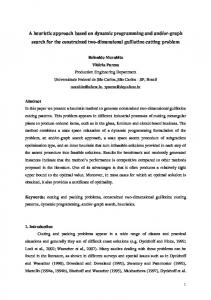
Time in hours Fig. 1. Solar power output power obtained from 1-min radiation data.
Moreover, larger BES capacity is not necessary when the proposed ramp-rate control approach is applied. 2. Limitations of MA and CES methods In this section MA and CES methods with their limitations are presented in detail. MA and CES methods are applied to smooth PV output power shown in Fig. 1. Output power from solar PV represents time series data, where the data points consist of successive measurement of PV power over a time interval (see Fig. 1). Average hourly solar radiation for a day in May for a typical location in Malaysia is extracted using HOMER software. Twenty-four hours radiation data have been interpolated to obtain 1440 values by adding normal distribution random noise with ‘0’ mean and standard deviation as ‘1’ [14]. The solar radiation is then redrawn to create 1 min radiation profile (Gn) during a day. 2.1. n-Period Moving Average (MA) method MA is essentially centered on finding out average for the set of input and the assumption is attributed that it represents a constant or level model. Moving averages is made by assuming that the latest ‘n’ period is more relevant and others are left out. The principle of operation of MA for ‘n’ relevant data points for the input having ‘k’ data points is given in Eq. (1) as,
F=
(i (k ) + i (k−1) + ...+i (k−n)) n
(1)
where n is number of relevant data points used in MA smoothing, i and F are input (PPV) and smoothed output respectively. For this work 41 data points are used as the moving average window therefore the value of n = 41. Expanding Eq. (1) for 41-point MA is given in Eq. (2) as,
i (k ) + i (k−1) + ...+i (k−41) ⎤ F=⎡ 41 ⎣ ⎦
(2)
As mentioned above for a 41-period moving average, 41 PPV data points which are most relevant for producing smoothed output is used and other data points are left out. A 41-period moving average can be thought of giving weights ‘1’ for the relevant data points considered for producing smoothed output and ‘0’ weights for the points left out. MA is able to capture the principle that the only relevant data points are important and non-relevant points do not contribute for the smoothing. From the above explanation we would like to highlight two main issues that are associated with MA which causes “memory effect”, (i) MA essentially ignores older data points by giving ‘0’ weights. (ii) The weights associated with relevant data points are equal which is not logical or acceptable.
297
Electrical Power and Energy Systems 96 (2018) 296–305
S. Sukumar et al.
b a
c d e f
Fig. 2. Actual PV power and smoothed power using 41 point MA waveform.
Fig. 3. Actual PV output and PV power smoothed using CES method.
The limitation of (MA) method is demonstrated using Fig. 2. For illustration purpose the 41-point MA smoothed waveform during the time period 13.5 h and 18.5 h is presented in Fig. 2 and it is obtained by smoothing the actual PV output power shown in Fig. 1. The actual solar PV power obtained from 1-min radiation data is compared with PV power smoothed by MA method. Noticing portions a, b, c, d, e and f in Fig. 2, there is no significant fluctuation in PV for which the battery supplied or absorbed significant amount of power which is due to memory effect [24].
0.5 will over smooth PV output power and if the value is more than 0.5 or nearer to 1, the smoothing will not be effective. There is no absolute reason presented in the literatures on choice of smoothing parameter pertaining to this PV ramp-rate control problem. The major drawback of using CES method is, the arbitrary choice of smoothing constant ‘α’ associated with the data points. For comparison with the proposed control strategy the value of ‘α’ is chosen as 0.2 which is predominantly found in the literature. For illustration purpose the smoothed waveform produced by CES method during the time period 13.5 h and 18.5 h is presented in Fig. 3. The portions encircled in dotted line shows that there is no significant fluctuation in PV output power, for which the battery will supply/absorb significant power due to memory effect. In other words the weights α,α(i-α),…,α(i-α)n distributed among the data points are not logically related to PV ramprate, therefore, creating “memory effect”. For this reason the BES is allowed to operate even though there is not significant fluctuation. The difference between CES and MA method is, CES method considers all the PV data points in the system and assigns progressively increasing weights to more recent data. On the other hand MA method consider only relevant PV data points and give equal weights to it and older data points are left out. Due to this memory effect, the CES and MA method will invariably smooth the PV output power even though there is no significant fluctuation.
2.2. Conventional Exponential Smoothing (CES) method CES method actually considers all the points in the system and gives progressively increasing weights to more recent data. The fundamental equation for CES is given in Eq. (3) as,
PPV̂ (i) = αPPV (i) + (1−α ) PPV̂ (i−1)
(3)
where PPV̂ (i) is smoothed output, PPV̂ (i−1) is smoothed output at previous step, PPV is the actual output power from solar PV and ‘α’ is the smoothing constant which should be selected between 0 and 1. Eq. (4) is formulated by substituting the value of PPV̂ (i−1) in Eq. (3) and is given as,
PPV̂ (i) = αPPV (i) + (1−α )[αPPV (i−1) + (1−α ) PPV̂ (i−2)]
(4) 3. Sensitivity analysis on MA and CES methods
Further, subsequent expansion of the above equation we get Eq. (5),
PPV̂ (i)= α [PPV (i) + (1−α ) PPV (i−1) + (1−α )2PPV (i−2) + (1−α )3PPV (i−3)
In this section, sensitivity analysis on MA and CES methods are carried out by using different window size and smoothing constant values respectively for the data shown in Fig. 1. From this analysis, the needs of new smoothing method can be justified.
+ ... + (i−α )nPPV (i−n)] + (1−α )nPPV̂ (i−(n−1)) (5) where ‘n’ is the number of PV data points in the time window. In Eq. (5), PPV̂ (i−(n−1)) denotes the forecast for the point n − 1 for which the
3.1. Analysis on MA method
value is ‘zero’. Therefore restructuring Eq. (5) gives Eq. (6) and is given as,
3.1.1. Variation of memory effect for different window sizes This analysis is conducted to show the variation of memory effect for different MA window sizes. In this analysis 5-point, 11-point, 31point, and 51-points MA window are applied. The PV output power smoothed by using MA method for these window sizes is plotted in Fig. 4. In this figure, only time periods between 16.5 h and 19 h is shown due to the presence of both significant and non-significant fluctuations in actual PV power. The corresponding battery power utilization for MA with different windows is plotted in Fig. 5. From Fig. 4, it is noticed that the actual PV output power can be smoothed using any window size. However, the smoothing effect increases as the MA window size increases. The difference between the smoothed waveform and actual PV power is the power required by the battery source to supply or absorb in order to limit the fluctuations (plotted in Fig. 5). When the 5-point MA method is applied, the energy supplied by the BES to smooth the fluctuations is 5.4 kW h for the said time period. On the other hand, the energy supplied by BES using 51-
PPV̂ (i)= α [PPV (i) + (1−α ) PPV (i−1) + (1−α )2PPV (i−2) + (1−α )3PPV (i−3) + ... + (i−α )nPPV (i−n)] (6) From Eq. (6) it is clear that the value of α,α(i-α),…,α(i-α)n is treated as the weights associated with the corresponding PV data points and is progressively decreasing to older data points. If the value of ‘α’ is greater than 0.5 or closer to 1 the contribution of the present value or the most recent value is weighed more and contribution of older terms is less for smoothing. If the value of ‘α’ is smaller than 0.5 or closer to 0, present value or the most recent terms will be weighed less and the older terms start contributing to the smoothing. Therefore, smoothing constant ‘α’ is the main parameter which helps to smooth PV fluctuations. Choosing the ‘α’ between 0 and 298
Electrical Power and Energy Systems 96 (2018) 296–305
S. Sukumar et al.
Actual ramp-rate already within limit + ramp limit
- ramp limit
a
Fig. 4. Smoothed PV output power produced using MA method for different windows.
Actual ramprate already within limit
Fig. 6. Ramp-rate control ability for MA method with different window values.
discharge/supply
Table 1 Ramp-rate control ability for MA method. MA window size
Ramp-rate in kW/min
5 pt 11 pt 31 pt 51 pt
± 16 ± 9.3 ± 3.3 ± 2.5
applied. For example, in portion ‘a’ (encircled in Fig. 6), the ramp-rate violation of −41.34 kW/min in actual PV ramp-rate can be noticed. The ramp-rate violation should be controlled to the desirable level (that is −20 kW/min). When 5 point, 11 point, 31 point and 51 point MA methods are applied, the ramp-rate at that particular instance are over smoothed to −9 kW/min, −2 kW/min, −0.75 kW/min, and −0.8 kW/ min respectively, which are unnecessary. Here the ramp-rate is controlled below the desirable level for which excessive battery power is utilized which results in large battery size.
charging/absorb
Fig. 5. Battery utilization for smoothing PV output power using MA method for different windows.
point MA window is 50.4 kW h. Thus, it can be concluded that memory effect varies from smaller to higher level as the value of MA window increases. In addition, the variation of memory effect also has an influence in determining the battery size.
3.2. Analysis on CES method 3.2.1. Variation of memory effect for different smoothing constants In this section an analysis on variation of memory effect for CES method with different smoothing constant (“α”) is analyzed. The applied smoothing constants are 0.1, 0.5, and 0.8. The results of PV output power smoothed by using CES method for these smoothing constant values is plotted in Fig. 7 for time periods of 16.5–19 h. The corresponding battery power utilization is plotted in Fig. 8.
3.1.2. Analysis on ramp-rate control ability of MA method In this analysis the ability of MA method with different window sizes to control the ramp-rate to desirable limit is analyzed. The ramprate limit is set to 10% of PV rated capacity. For our study we analyse the fluctuations from a 200 kW PV plant, therefore the ramp-rate limit is set to ± 20 kW/min. From the analysis it has been found that MA method with different window sizes have the ability to control the PV ramp-rates within the limit. During the entire PV operation it has been noticed that the extent of control of ramp-rate decreases as the MA window size increases. For example when 5 point MA is applied the ramp-rate is controlled within ± 16 kW/min. On the other hand when 51-point MA is used, the ramp-rate is controlled within ± 2.5 kW/min. The ramp-rate control ability of MA with different window values is plotted in Fig. 6 for time periods 16.5 h–19 h and the values are tabulated in Table 1. There are instances where the actual PV ramp-rate is already within the limit (encircled in Fig. 6) for which the MA methods allow the battery storage to operate. The BES operation during these instances is evident in Fig. 5. This unnecessary operation will contribute to reduction in BES’s life span. Over smoothing of ramp-rate is also evident when the MA method is
Fig. 7. Smoothed PV output power produced using CES method for different “α”.
299
Electrical Power and Energy Systems 96 (2018) 296–305
S. Sukumar et al.
discharge/supply
Actual ramp-rate already within limit
+ramp limit
-ramp limit CES inability to control ramp-rate when alpha=0.5
charge/absorb
CES inability to control ramp-rate when alpha=0.8
Fig. 8. Battery utilization for smoothing PV output power using CES method for different “α”.
b
Actual ramp-rate already within limit
Fig. 9. Ramp-rate control ability for CES method with different smoothing constant values.
From Fig. 7, it can be noticed that the actual PV output power is smoothed for any value of “α”. However, the smoothing effect increases as the value of “α” decreases from “1”. The difference between the smoothed waveform and actual PV power is the power required by the battery source to supply or absorb in order to limit the fluctuations (plotted in Fig. 8). When the CES method with “α = 0.8” is applied, the energy supplied by the BES to smooth the fluctuations is 0.426 kW h for the said time period. On the other hand when CES method with “α = 0.1” is applied, the energy supplied by the BES is 16.76 kW h. Thus, it is evident that the memory effect varies from smaller to higher level as the values of “α” progressively decreases from “1”. Moreover, the variation of memory effect also has an influence in the required battery size. For example, the CES method with “α = 0.1” will have larger influence of memory effect and requires 102.3 kW h BES storage to smooth the fluctuations. On the other hand CES method with “α = 0.8” will have lower influence of memory effect and requires only 4 kW h BES storage to smooth the fluctuations.
Table 2 Ramp-rate control ability for CES method. CES with different “α”
Ramp-rate in kW/min
0.1 0.5 0.8
± 6.7 ± 25.8 ± 40
min. 4. Proposed ramp-rate control strategy MA and CES method allows excessive use of BES which will reduce its operating life. Moreover, this excessive usage will result in larger BES capacity when MA or CES methods are applied. The limitations of MA and CES methods are addressed by the proposed ramp-rate control strategy. The proposed ramp-rate control strategy uses exponential smoothing method with modifications. Therefore the fundamental equation of exponential smoothing method with the proposed smoothing parameter ‘σ’ is given in Eq. (7) as,
3.2.2. Analysis on ramp-rate control ability of CES method In this analysis the ability of CES method with different smoothing constants to control the ramp-rate to desirable limit is analyzed. During the entire time of PV operation it was noticed that the extent of control of ramp-rate increases as the value of smoothing constant “α” decreases when CES method is applied. For example when CES method with α = 0.8 is applied the ramp-rate is controlled within ± 40 kW/min. Similarly when CES method with α = 0.1 is applied the ramp-rate is controlled within ± 6.7 kW/min. The ramp-rate control ability of CES method with different smoothing constants “α” is plotted in Fig. 9 for time period 16.5–19 h and the values are tabulated in Table 2. It was found that CES method is unable to limit the ramp-rate to the desirable limit for many instances when the smoothing constant values are 0.5 and 0.8. For example, this inability is evident (encircled in Fig. 9) when “α = 0.5 and 0.8”. There are instances where the actual PV ramp-rate is already within the limit (encircled in Fig. 9), but CES method allows the BES to operate. Over smoothing of ramp-rate is also evident when applying CES method. For example, in portion ‘b’ (encircled in Fig. 9), the actual ramp-rate violation of −41.34 kW/min can be noticed. The CES method with α = 0.1 caused over smoothed of ramp rate to −3.4 kW/ min. Here the ramp-rate is controlled below the desirable level for which excessive battery power is utilized therefore resulting in large BES size. On the other hand, CES methods with α = 0.5 and 0.8 is unable to control the ramp-rate within the limit. For CES method with α = 0.5 the ramp-rate is controlled till −22.7 kW/min and for CES method with α = 0.8 case the ramp-rate is controlled till −34.9 kW/
PPV̂ (i) = σPPV (i) + (1−σ ) PPV̂ (i−1)
(7)
where PPV̂ (i) is the smoothed PV output for the instant ‘i’, PPV̂ (i−1) is the smoothed PV output for the instant ‘i − 1’ and PPV(i) is the actual PV output power for the instant ‘i’. Unlike the smoothing parameter ‘α’ in Eq. (3), the proposed smoothing parameter ‘σ’ in Eq. (7) change for every time step depending on the ramp-rate violations. Therefore, the ramp-rate has to be checked for any violation for every time step. Based on the level of violation the smoothing parameter ‘σ’ is calculated. The ramp rate of solar PV output power at instant ‘i’ is given in Eq. (8) as,
dPPV [P (i)−PPV (i−1)] (i) = PV dt t (i)−t (i−1)
(8)
where PPV(i) and PPV(i − 1) are actual powers at ith and (i − 1)th instant. Likewise the difference between actual PV power at instant ‘i’(PPV(i)) and smoothed PV power at instant ‘i − 1’ (PPV̂ (i−1) ) also denotes the ramp-rate and is expressed in Eq. (9) as,
dPPV [P (i)−PPV̂ (i−1)] (i) = PV dt t (i)−t (i−1)
(9)
For this work 10% of solar PV’s rated capacity per minute is taken as ramp-rate limit. The ramp-rate beyond the prescribed limit is noted as 300
Electrical Power and Energy Systems 96 (2018) 296–305
S. Sukumar et al.
Eq. (12) is 1 (Fig. 12) for which the battery is also switched OFF. Therefore the values of smoothed PV power (PPV̂ ) and actual PV output (PPV) are same for the time period t1–t4. From t4 to t5 there is a significant fluctuation in PV output power (PPV). Therefore the ramp-rates are calculated and checked for violation. Using the ramping function f (RR) the appropriate value of smoothing parameter ‘σ’ is calculated from which the battery switching is also decided. Finally, the smoothed output PPV̂ is calculated from Eq. (14) and since actual PV power (PPV) is more than the smoothed power (PPV̂ )the battery has to be operated in charging mode in order to limit the ramp-rate. There is no significant power fluctuation in actual PV power from t5 to t6 but dPPV exceeds the dt ramp limit. Therefore the ramp-rate for the smoothed waveform is limited and the smoothed reference to time instant t6 is calculated (PPV̂ (t 6) ). During this time period the battery is charged. Between t6 and t7 the ramp-rates are within the limit therefore PPV̂ (t 7) is equal to PPV(t7). Therefore the smoothing parameter ‘σ’ for the time period t7 reaches 1 for which the battery is switched OFF. Similarly the ramp-down is controlled by discharging the battery between the period t7–t10 where the variation in the smoothing parameter ‘σ’ during this period is presented in Fig.12. From t10 to t14 there is no significant fluctuation in PV output (PPV), therefore the smoothed output (PPV̂ ) and actual PV output (PPV) remains the same. During this time period the value of smoothing parameter ‘σ’ is also ‘1’ and the battery is also switched OFF. It is clear from Fig. 11 that battery is used only to smooth out the ramp ups and downs. The proposed ramp-rate control strategy is applied to a 200 kW PV plant where the ramp-rate is controlled by a 200 kW h Battery Energy System (BES).
violation. Therefore, Eqs. (8) and (9) are checked for ramp violation using a ramp-rate function f(RR) given in Eq. (10), which is basically used to limit the PV ramp-rate. The f(RR) is illustrated as follows, dP
f (RR) =
dP
⎧ dtPV (i), if | dtPV (i)| ⩽ |RRlim | and | ⎨ RRlim, otherwise ⎩
dPPV dt
(i)| < |RRlim | (10)
The proposed ramping function f(RR) is added with smoothed power at previous instant ‘i − 1’ (PPV̂ (i−1) ) to obtain the smoothed power at instant ‘i’ PPV̂ (i) and is given in Eq. (11).
PPV̂ (i) = PPV̂ (i−1) + f (RR)
(11)
By equating the Eqs. (7) and (11) the proposed smoothing parameter (σ) is given in Eq. (12) as,
σ=
f (RR) PPV (i)−PPV̂ (i−1)
(12)
The calculated smoothing parameter (σ) is substituted in Eq. (7) to find out smoothed output PPV̂ for every time instant. A discrete switching function S(i), based on the smoothing parameter ‘σ’ is given in Eq. (13) to obtain optimal battery operation.
0, for σ = 1 S (i) = ⎧ 1, for σ < 1 ⎨ ⎩
(13)
By introducing the switching function S(i) in Eq. (7) gives Eq. (14) which can be expressed as,
PPV̂ (i) = σPPV (i) + [(1−σ ) PPV̂ (i−1)] S (i)
(14) 5. Simulation results
Eq. (14) is the final control equation from which the smoothed PV output power PPV̂ (i) for instant ‘i’ is obtained. The difference between the smoothed power (PPV̂ ) and the actual PV output power (PPV) gives the target power required by the battery (PSET) to absorb or inject in order to control the PV ramp-rate within the limit and is given in Eq. (15) as,
PSET (i) = PPV̂ (i)−PPV (i)
The test system consists of grid connected PV and BES as shown in Fig. 13. The test system is modelled and the simulation is carried out using PSCAD software. The specifications of the test system are given in Table 3. A single diode model of solar PV cell is implemented to build the PV plant. The PV plant is operated in unity power factor. In this work single stage controller is utilized to control the voltage source converter (VSC) of PV plant. In the single stage controller mechanism, the power from the DC side is transferred to AC side by regulating the voltage at DC link. The error between the square of the reference voltage set by MPPT and square of the measured DC bus voltage is sent to PI controller. The output from the PI controller is added to instantaneous power from PV array to obtain the reference power. This reference power is then sent to inner power control loop. The BES is modelled by incorporating the effect of internal resistance and Peukert equation in order to obtain battery voltage and SOC [14]. The charge level in the battery is determined from the battery voltage level. The charge controllers were used to protect the battery from deep discharging and over charging. Therefore the voltage level is continuously monitored using charge controllers to prevent the battery from deep discharging. Bulk or current charging and constant voltage charging schemes were used to protect the battery from over charging. Current control mode is incorporated to control the VSC of BES plant. The inputs to the inner current control loop are the dq reference current vectors which are produced from output power control loop. The maximum charging and discharging limit for the BES is set at −200 kW and 200 kW respectively.
(15)
If PSET is positive the battery will discharge, and if negative the battery will operate in charging mode. A simple illustration for generation of target power (PSET) for the battery is given in Fig. 10. The illustration of the proposed ramp-rate control strategy is provided in Fig. 11. It should be noted that the time interval between subsequent points in Figs. 11 and 12 is 1 min. During the time period t1–t4, the ramp-rates are calculated using Eqs. (8) and (9). The calculated ramp-rates are checked for any violation using Eq. (10) and the appropriate ramping function f(RR) is calculated. Since there is no violation in ramp-rates the smoothing parameter ‘σ’ calculated using
5.1. Overall results In this section the overall results on application of the proposed ramp-rate control strategy to control the ramp-rate from solar PV within the desirable level is presented. The proposed ramp-rate strategy is compared with 41-point MA and CES method. The aim is to limit the ramp-rate of PV output power by 10% of PV rated capacity which
Fig. 10. Calculating PSET for battery.
301
Electrical Power and Energy Systems 96 (2018) 296–305
S. Sukumar et al.
Fig. 11. Operational method for proposed ramp-rate control strategy.
battery ON
battery OFF
charging
battery OFF
ˆ P PV PPV PSET
discharge
is ± 20 kW/min. In other words, any ramps from the PV output power within this limit is allowable and above the limit will be limited by absorbing or injecting power from BES. A 200 kW h lead-acid BES is used in the simulation. The BES is permitted to operate between 30% and 100% state of charge (SOC). At initial condition the SOC of the battery is set to 70% thereby allowing it to charge/discharge. The overall results for mitigation of PV output power fluctuation using MA, CES with α = 0.2 and proposed ramp-rate control strategy are shown in Figs. 14, 15, and 16. From Figs. 14, 15, and 16, it is clear that all the 3 methods can mitigate fluctuations in PV output power. However the proposed ramprate control strategy has the ability to control the ramp-rates to the desirable level which is highlighted from the results presented in next section.
Fig. 12. Variation in smoothing parameter for the proposed ramp-rate strategy.
50Hz AC Grid Network
5.2. Performance analysis of smoothing PV output methods
BKR Grid
In this section the results on ability of the proposed method to control the ramp-rate to desirable level are discussed. Fig. 17 presents actual PV power with smoothed power using MA, CES and the proposed method for the time period 17–19 h. The ramp-rate for this time period for the three methods is presented in Fig. 18. The figure shows the ability of the methods to control the ramp rate to the desirable level, which is ± 20 kW/min. Corresponding BES utilization for the three methods are shown in Fig. 19. In order to highlight the effectiveness of the proposed method, three portions are selected to present different scenarios; ‘c’ and‘d’ represents non-significant fluctuation and ‘e’ representing ramp-rate violation events in Figs. 17, 18 and 19. In Fig. 18, during the time periods ‘c’ and ‘d’ the actual ramp-rate is found to be within the limit. However, when MA and CES methods are applied the ramp-rate is further reduced. As a result in Fig. 19, it can be seen that the BES is operated during the time duration of ‘c’ and ‘d’ when both methods are applied. These non-significant fluctuating
0.400/11kV 1 MVA 0.4kV bus BKR load
BKR PV
BKR BES VSC BES
VSC PV
L o a d
Photovoltaic array 200kW
BES 200kWh
Fig. 13. Schematic of grid connected PV-BES system.
Table 3 Specification of the test system. System Specifications
Capacity
PV generation BES capacity Frequency Voltage (L-L)
200 kW 200 kW h 50 Hz 400 V
Fig. 14. Smoothing PV output power by using MA method.
302
Electrical Power and Energy Systems 96 (2018) 296–305
S. Sukumar et al.
Ramp-rate already within limit +ramp limit
c d
-ramp limit
e
Ramp-rate violation event
Fig. 15. Smoothing PV output power by using CES method.
Fig. 18. Ramp-rates for the three methods.
Battery usage for ramp-rate within the limit for MA and CES methods.
c
e
d
Battery utilization during ramp-rate violation events
Fig. 16. Smoothing PV output power by using proposed ramp-rate method.
Fig. 19. BES utilization for the three methods.
Ramp-rate violation event
33.04 kW when MA and CES methods are applied respectively. On the other hand when the proposed method is applied the BES discharges only 21.34 kW in order to limit the ramp-rate exactly to the desirable level (−20 kW/min). This can be seen in portion ‘e’ in Fig. 19. The BES will supply or absorb excessive power when MA or CES method is applied. On the other hand, the proposed method causes the BES to charge or discharge exactly the required power to ensure the ramp-rate is controlled exactly to the desirable limit. The ramp-rate profile of the smoothed PV output for the proposed method for entire duration of PV operation is presented in Fig. 20. From the figure it is clear that the proposed method limits the ramp-rate
e
c
d
Ramp-rate already within limit
Fig. 17. Smoothing PV output power for specific hours using MA, CES, and proposed ramp-rate strategy.
events supposedly shouldn’t be considered for battery operation since the ramp-rate is within the limit. The continuous BES operation will affect the BES’s life span in long run. Deep discharging and frequent charging decreases battery life [25]. On the other hand, when the proposed method is applied, the output power from the BES is maintained “zero” or switched OFF for ramp-rates which are within the limit. This is evident from Fig. 19 for the ‘c’ and ‘d’. An incident of ramp-rate violation in actual PV power is shown in portion ‘e’ of Figs. 17 and 18 at 18.01 h and is recorded as −41.34 kW/ min. The BES has to discharge power in order to control this negative ramp-rate violation. When MA and CES methods are applied the ramprate violation is over smoothed to −7kW/min and −8.3 kW/min respectively. As a result the BES has to discharge about 34.3 kW and
+ve Ramp limit
-ve Ramp limit
Fig. 20. Ramp-rate profile of smoothed PV power for proposed method.
303
Electrical Power and Energy Systems 96 (2018) 296–305
S. Sukumar et al.
Table 4 Comparison on number of instances BES is switched ON for three methods. Method
Number of charging instances of BES
Number of discharging instances of BES
Number of instances BES is switched ‘ON’
MA method CES method Proposed strategy
370 347 36
448 444 49
All the time All the time 85
violations. 6. Discussion Table 4 shows a comparison between the three methods for the number of instances BES is switched ON. It was noticed that there are 85 instances of ramp-rate violation events. Using the proposed ramprate control strategy, the BES is switched ON only during those instances. The smoothing parameter calculated using Eq. (12) will be less than ‘1’ for those instances. During remaining instances, the BES is switched OFF since the PV ramp-rate is within the limit. Here the value of smoothing parameter is ‘1’. On the other hand, when MA or CES method is used to smooth PV output power fluctuation the BES is switched ON all the time. From Table 2, it is evident that when the proposed ramp-rate control strategy is used the number of charging and discharging instances of BES is very less because the battery source is switched ON only during ramp-rate violation events. The proposed ramp-rate control method can be applied for both planning and real-time application. For planning, it can be used to design the microgrid system, mainly on the estimating appropriate battery size. For real time application, real time data (irradiance) or short time forecasting of the PV output (based on predicted irradiance) can be used by the proposed method to determine the smoothing of PV output. In general, the level of accuracy of the forecasting will influence the proposed method outcomes for planning and real time applications. The following are the advantages of the proposed ramp-rate control strategy over MA and CES method,
Fig. 21. Variation of BES SOC level for the three methods.
violation exactly to desirable level. 5.3. Variation of BES SOC profile and smoothing parameter Variation of BES SOC level for all the three methods are shown in Fig. 21. It can be noticed that the variation in SOC is large when MA and CES methods are applied. This variation in SOC level is due to, (i) unnecessary operation of BES even though the ramp-rates are within the limits and (ii) excessive charge or discharge of BES power to over smooth the ramp-rates. As a result large capacity of BES is required when MA and CES methods are applied, which will eventually increase its capital cost. On the other hand, when the proposed method is applied the variation of BES’s SOC level is less. This is because the proposed method will allow the BES to operate only during ramp-rate violation events and for remaining hours the power from the BES is ‘zero’ or switched OFF. From the analysis of results shown in Fig. 21, it was found the total amount of energy needed to control the ramp-rate using the proposed method is around 8.13 kW h. This value is much lower than the size of the battery in the system, which is 200 kW h. Based on this finding, the proposed method can also used to find suitable battery size for the system in order to avoid battery oversize. On the other hand for MA and CES methods the total amount of energy needed to control the ramp-rate is 200 kW h and 102 kW h. Fig. 22 gives clear picture of variation of smoothing parameter ‘σ’ for entire time of operation. It can be observed that the value of smoothing parameter is ‘1’ when the ramp-rate is within the limits. The value of smoothing parameter will be less than ‘1’ for ramp-rate
(i) The proposed ramp-rate control strategy considers all data points present in the system. (ii) The weights associated with the data points are not equal. (iii) The choice of smoothing parameter ‘σ’ associated with the data points for the proposed ramp-rate control strategy is not arbitrary and it depends on PV ramp-rate. (iv) Since the weights distributed in PV data points are based on PV ramp-rate, the phenomenon called ‘memory effect’ found in MA or CES method is removed. (v) The proposed ramp-rate control strategy does not require BES to operate all the time therefore reducing the size of BES capacity considerably and also contribute to increase in battery life span. 7. Conclusion A new method to control the PV output power ramp-rate to desirable level using BES is proposed in this paper. The proposed method has been compared with MA and CES methods. From the analysis it was found that the distribution of weights associated with PV data points in MA and CES methods is not based on PV ramp-rates, thus creating memory effect. This causes switching of BES all the time to smooth the PV output power. On the other hand, the proposed strategy does not exhibit memory effect as the weights associated with the PV data points are based on PV ramp-rates. The proposed control strategy allows the BES to operate only during ramp violation events for which the BES optimally charges/discharges to control the ramp-rate to the desirable
Fig. 22. Variation of smoothing parameter ‘σ ‘for proposed ramp-rate strategy.
304
Electrical Power and Energy Systems 96 (2018) 296–305
S. Sukumar et al.
level. The test results show that the proposed method caused the BES to switch ON for 85 min, which constitutes to only 10.9% of BES operation as compared to MA or CES methods. With the less switching of BES using the proposed method, the life span of BES can be increased. Moreover the proposed approach does not allow the BES to over smooth the ramp-rate. Therefore, when the proposed method is applied, the size of BES capacity required for PV ramp-rate control application can be reduced.
[12]
[13]
[14]
References
[15]
[1] Sugihara H, Yokoyama K, Saeki O, Tsuji K, Funaki T. Economic and efficient voltage management using customer-owned energy storage systems in a distribution network with high penetration of photovoltaic systems. IEEE Trans Power Syst 2013;28:102–11. [2] Gevorgian V, Booth S. Review of prepa technical requirements for interconnecting wind and solar generation, National Renewable Energy Laboratory: Golden, CO, U. S. Department of Energy, USA; 2013. [3] Omran WA, Kazerani M, Salama MMA. Investigation of methods for reduction of power fluctuations generated from large grid-connected photovoltaic systems. IEEE Trans Energy Convers 2011;26:318–27. [4] Ina N, Yanagawa S, Kato T, Suzuoki Y. Smoothing PV system's output by tuning MPPT control. IEEJ Trans Power Energy 2004;124:455–61. [5] Kakimoto N, Satoh H, Takayama S, Nakamura K. Ramp-rate control of photovoltaic generator with electric double-layer capacitor. IEEE Trans Energy Convers 2009;24:465–73. [6] Monai T, Takano I, Nishikawa H, Sawada Y. A collaborative operation method between new energy-type dispersed power supply and EDLC. IEEE Trans Energy Convers 2004;19:590–8. [7] Tam KS, Kumar P, Foreman M. Enhancing the utilization of photovoltaic power generation by superconductive magnetic energy storage. IEEE Trans Energy Convers 1989;4:314–21. [8] Rahman S, Tam KS. A feasibility study of photovoltaic-fuel cell hybrid energy system. IEEE Trans Energy Convers 1988;3:50–5. [9] Hund TD, Gonzalez S, Barrett K. Grid-Tied PV system energy smoothing. 35th IEEE photovoltaic specialists conference (PVSC). 2010. p. 2762–6. [10] Darras C, Muselli M, Poggi P, Voyant C, Hoguet JC, Montignac F. PV output power fluctuations smoothing: The MYRTE platform experience. Int J Hydrogen Energy 2012;37:14015–25. [11] Li X, Li Y, Han X, Hui D. Application of fuzzy wavelet transform to smooth wind/PV
[16]
[17]
[18]
[19] [20] [21]
[22]
[23]
[24]
[25]
305
hybrid power system output with battery energy storage system. Energy Proc 2011;12:994–1001. Saez-de-Ibarra A, Martinez-Laserna E, Stroe DI, Swierczynski M, Rodriguez P. Sizing study of second life li-ion batteries for enhancing renewable energy grid integration. IEEE Trans Ind Appl 2016;52:4999–5008. Datta M, Senjyu T, Yona A, Funabashi T, Kim CH. Photovoltaic output power fluctuations smoothing methods for single and multiple PV generators. Curr Appl Phys 2010;10:S265–70. Koohi-Kamali S, Rahim NA, Mokhlis H. Smart power management algorithm in microgrid consisting of photovoltaic, diesel, and battery storage plants considering variations in sunlight, temperature, and load. Energy Convers Manage 2014;84:562–82. Tesfahunegn SG, Ulleberg Ø, Vie PJ, Undeland TM. PV fluctuation balancing using hydrogen storage–a smoothing method for integration of PV generation into the utility grid. Energy Proc 2011;12:1015–22. Traube J, et al. Mitigation of solar irradiance intermittency in photovoltaic power systems with integrated electric-vehicle charging functionality. IEEE Trans Power Electron 2013;28:3058–67. Li X, Hui D, Lai X. Battery energy storage station (BESS)-based smoothing control of photovoltaic (PV) and wind power generation fluctuations. IEEE Trans Sust Energy 2013;4:464–73. Ellis A, Schoenwald D, Hawkins J, Willard S, Arellano B. PV output smoothing with energy storage. 38th IEEE photovoltaic specialists conference (PVSC). 2012. p. 001523–8. Johnson J, et al. PV output smoothing using a battery and natural gas enginegenerator. 39th IEEE photovoltaic specialists conference (PVSC). 2013. p. 1811–6. Marcos J, Storkël O, Marroyo L, Garcia M, Lorenzo E. Storage requirements for PV power ramp-rate control. Sol Energy 2014;99:28–35. Johnson J, Schenkman B, Ellis A, Quiroz J, Lenox C. Initial operating experience of the La Ola 1.2-MW photovoltaic system Sandia Report U.S. Department of Energy; 2011. De la Parra I, Marcos J, García M, Marroyo L. Control strategies to use the minimum energy storage requirement for PV power ramp-rate control. Sol Energy 2015;111:332–43. Marcos J, de la Parra I, García M, Marroyo L. Control strategies to smooth shortterm power fluctuations in large photovoltaic plants using battery storage systems. Energies 2014;7:6593–619. Alam MJE, Muttaqi KM, Sutanto D. A novel approach for ramp-rate control of solar PV using energy storage to mitigate output fluctuations caused by cloud passing. IEEE Trans Energy Convers 2014;29:507–18. Amiri M, Esfahanian M, Hairi-Yazdi MR, Esfahanian V. Minimization of power losses in hybrid electric vehicles in view of the prolonging of battery life. J Power Sources 2009;190:372–9.