Random Adjacent Sequences An Efficient Solution for Logic BIST René David Laboratoire d'Automatique de Grenoble BP 46, 38402 St-Martin-d'Hères, France
[email protected]
Patrick Girard, Christian Landrault, Serge Pravossoudovitch, Arnaud Virazel* Laboratoire d'Informatique, de Robotique et de Microélectronique de Montpellier 161, rue Ada, 34392 Montpellier Cedex 5, France
[email protected] [email protected] [email protected] [email protected]
* The author works now in the Computer Architecture Lab – University of Stuttgart Breitwiesenstrasse 20-22, 70565 Stuttgart, Germany
[email protected]
Abstract:
High defect coverage requires good coverage of different fault types. In this paper, we present a comprehensive test vector generation technique for BIST, called Random Single Input Change (RSIC) generation, that can be used to generate tests for many arbitrary misbehaviors that can occur in digital systems, thus providing a single on-chip test generation solution. By proving the effectiveness of universal test sequences produced by such a generation technique in detecting stuck-at, path delay and bridging faults, we demonstrate that using RSIC generation is one of the best and most practical way to reach a high level of defect coverage during BIST of digital circuits.
Key words:
BIST, Stuck-at Fault, Bridging Fault, Delay Fault, Universal Sequence.
1
2
1.
René David
INTRODUCTION
In the near future, the recent advances in deep-submicron IC process technology and core-based IC design technology will lead to a widespread use of logic BIST in industry. This is confirmed by the ITRS (International Technology Roadmap for Semiconductors) statement that by 2014 it may cost more to test a transistor than to manufacture it unless techniques like logic BIST are employed [1]. Logic BIST, which test logic circuits through the use of built-in pattern sources and response evaluators, offers a number of advantages compared with external testing, which is becoming more and more difficult and costly [2]. A first problem that occurs with external testers is that they are several times slower than the circuits they have to test. Purchasing high speed testers that meet the performances of new designs requires a huge investment. Moreover, even with those high speed testers, it is not always possible to have a timing accuracy comparable to the IC internal speed [2]. In this context, BIST represents an attractive test solution since it allows at-speed testing, thus solving timing accuracy and test time related problems encountered with traditional external testers. In addition, BIST drastically reduces the amount of test data exchanged with the tester, thus reducing the need for complex external testing equipment. BIST can hence be run on a very low cost tester. Finally, BIST may relieve the problem of tester capacity [3] and the problem of low accessibility of internal nodes of the design, which increases the test complexity [4]. The growing need for performance-related testing (called delay testing) also demands BIST solutions. Deep-submicron technologies introduce new performance-related defect types, and the increasing clock frequencies in high-speed designs impose aggressive timing margins. While the internal clock frequencies have risen by 30% per year, the accuracy of external test equipment has improved at a rate of only 12% per year [1]. Hence, it is becoming increasingly difficult to do performance-related testing using external test equipment. BIST may solve this problem since it allows to do accurate delay testing and precision measurement on-chip. Test pattern generation for BIST can be broadly classified into deterministic, mixed-mode, pseudo-random (flat or weighted) and exhaustive generation. Deterministic BIST consists in storing pre-computed test patterns on-chip by using a special-purpose hardware [5]. Deterministic BIST has been shown to be efficient in terms of fault detection but the price for obtaining complete fault coverage usually is a relatively large silicon area overhead. Moreover, deterministic BIST is always related to a specific fault model. Mixed-mode BIST consists in using a limited number of pseudorandom patterns to eliminate easy to detect faults and deterministic patterns
Random Adjacent Sequences
3
to cover the remaining random patterns resistant faults [6]. The deterministic patterns are either stored on-chip in a compressed format and expanded during BIST [7] or directly embedded into an LFSR sequence by “bit-fixing” or “bit-flipping” techniques [8]. Mixed-mode BIST is less hardware consuming compared with deterministic BIST, but is also less efficient in terms of test quality (fault coverage vs test length) and is often extremely tailored to a specific circuit. Moreover, mixed-mode BIST is related to a specific fault model. Pseudo-random BIST consists in applying test patterns that exhibit randomness but which are generated using special-purpose hardware (LFSR or Cellular Automata) and are thus repeatable [9,10,11]. Pseudo-random BIST is the least hardware consuming solution but requires test lengths which may be long in some cases. Pseudo-random BIST is not related to a specific fault model. Exhaustive (or pseudo-exhaustive) BIST consists in applying all (or nearly all) the logic combinations at the circuit inputs [12]. Pseudo-exhaustive BIST is not related to a specific fault model, but cannot be used in practice due to high testing time and circuit segmentation requirement. The goal in this paper is to propose a new test generation technique for BIST that can be used to generate tests for many arbitrary misbehaviors that can occur in digital systems, thus providing a single on-chip test generation solution. The reason for using such kind of “universal” test sequences can be explained as follows. The classical single-stuck fault (SSF) model continues to be the most commonly used fault model in digital systems testing. However, defects in new nanometer CMOS technologies do not always behave like stuck-at faults [13]. Therefore, test generation based on the SSF model alone is no longer sufficient for obtaining high defect coverage [14,15]. On the other side, the use of multiple test generation techniques that each targets a specific fault type (such as transition, bridging or stuck-open fault type) would be costly and unpractical from a BIST point of view. For this reason, we propose an alternative solution consisting in the use of a single on-chip test pattern generator providing universal test sequences that target both conventional (stuck-at) and non-conventional (delay, bridging, stuck-open) fault types. The question now is: what kind of BIST test pattern generation do we need to use for generating such “universal” test sequences? According to the above presentation of BIST test generation approaches, the only practical solution is to use pseudo-random BIST as this approach is not related to a specific fault model, i.e. test patterns are determined irrespective of the targeted fault type. However, the only problem that remains with pseudorandom BIST is the test length, which is acceptably long to test for SSFs, but which is prohibitively long to test for delay faults [16]. A solution to solve this problem is to use Random Single Input Change (RSIC) test sequences,
4
René David
that have been shown to be efficient to test path delay faults with a reasonable test length [17]. RSIC test sequences are single input change (also called adjacency) test sequences that have to be generated in such a way that they have practically the properties of pure random sequences. This can be performed through the use of an LFSR with improved random properties for example. Moreover, the selection of the changing bit (between two consecutive patterns) has also to be performed randomly. The remainder of this paper is organized as follows. Section 2 gives preliminary definitions on the considered fault models and the test sequences used. Section 3 highlights the effectiveness of RSIC generation, first for delay fault detection and next for SSF and bridging fault detection. Concluding remarks are given in Section 4.
2.
BASICS AND BACKGROUND
2.1
Basics on fault models
Fault models describe the logical behavior of a faulty system [18]. In this work, several fault models have been considered to exhibit the effectiveness of test sequences produced from a RSIC generation. The classical and most widely-used SSF model is obviously considered. Two other fault models are also used: the bridging fault (BF) model and the path delay fault (PDF) model. Basic definitions and notations on these fault models are now given. A bridging fault can be viewed as an unintentional short between two lines. This short can be a non-resistive short such that the two lines are always brought into equilibrium at the same potential or a resistive short such that the potential between the shorted lines is different. Therefore, after the popular wired-AND and wired-OR models used to model the effects of bridging faults in bipolar logic [19], several models for the resistive and nonresistive fault types of bridging faults were proposed. However, these models suffer from a number of limitations. The primary drawback of the non-resistive fault model is that it is not guaranteed to detect resistive bridging faults. While resistive BF models are more realistic, they fall short of modeling all bridging type anomalies since the number of possible BF anomalies is intractable for most circuits [20]. Although the coverage of a bridging fault by both wire-AND and wireOR behavior does not always guarantee detection, these models have the advantage to be easy to consider during BF simulation. Moreover, it has been proven recently that a high gate level SSF coverage implies high BF coverage [21]. Consequently, the rest of this paper is based on the use of such models to represent bridging defects that occur in digital circuits. The
Random Adjacent Sequences
5
BF site extraction problem has not been dealt with since the lists of realistic bridging faults considered during the evaluation of RSIC test sequences were provided by the Lisboa Technical University (INESC/IST). Some defects in a manufactured circuit do not affect the logic function of the circuit, rather they change the delays of some gates, thus altering the speed at which the circuit can operate. Such defects are referred to as delay defects and delay fault testing is the term used for the methodology of detecting such defects by checking whether a manufactured circuit meets its timing characteristics. The fault model most widely studied in this context is the path delay fault model [22]. The main advantage of using the path delay fault model is that it models the real distributed delay defects very well compared with other existing delay fault models, namely the gate delay fault model and the transition delay fault model. However, an important feature of the path delay fault model is that the single fault assumption is not realistic since a single defect usually affects a large number of paths. For this reason, a robust test is preferred to detect a path delay fault. A test for a path is robust if it can detect a delay fault on the path irrespective of other delays and delay faults in the circuit, otherwise it is non-robust [22]. Detection of path delay faults requires two-pattern tests. An initialization vector is applied and the circuit is allowed to stabilize. Then, the test vector is applied and the circuit outputs are sampled at clock speed. The response is then compared to that of the fault-free circuit to determine the presence or the absence of a delay fault. Hence, correct operation of a circuit at the intended speed can only be guaranteed if there is no path delay that exceeds the value determined by the clock period [23].
2.2
Theoretical basis of RSIC generation
In general, two-pattern tests may differ in multiple bit positions. In this case, they are called multiple input change (MIC) pattern pairs. Test pairs that differ only in one bit position are called single input change (SIC) pattern pairs. Let us now define what a RSIC sequence should be from a theoretical point of view (we assume equal likelihood of all vectors). Let S = V(1)V(2)...V(l)...V(L), (1) be a test sequence composed of L successive n-bit vectors V(l). Each vector takes a value from the set V = {V0, V1, ..., V2 n −1 }, (2) where Vj corresponds to the n-bit vector (x1,x2, …,xn) associated with the decimal value j. For example, for n = 5, V9 = 01001, i.e., x1 = x3 = x4 = 0 and x2 = x5 = 1. In a Random MIC (called RMIC) sequence, the probability Pr[V(l) = Vj] = 1 / 2n for any l and any j, and the probability Pr[V(l) = Vj] is
6
René David
independent of the values V(i), where i = 1, 2, …, l−1. In a RSIC sequence, this probability is: Pr[V(l) = Vj V(l−1) = Vk] =
1 ,iff j − k = 2a, n
(3)
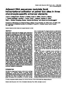
where a is a non-negative integer. In other words, for any l > 0, V(l) differs from V(l−1) by exactly one bit randomly drawn, and this bit must be independent of the bits previously drawn. Figure 1 represents the basic principle of an RSIC generation. This principle is taken from [24]. Basically, a k-bit random (in fact pseudorandom) source is used; this source may be a random number obtained from a maximal length LFSR. The value of the vector Q1Q2....Qk changes at each clock cycle of the test session. At each time l, a subset of m bits is used (m ≤ k). The vector R(l) = R1(l)R2(l)....Rm(l) is transformed into a n-bit vector V(l) = x1(l)x2(l)....xn(l) which is applied to the circuit under test. In order to agree with the definition of a RSIC sequence given above, the following points have to be addressed: 1. R(l) is independent of R(l−1). 2. The transcoding between R(l) and V(l) satisfies Equ.(3), at least approximately. 3. The period of the sequence S = V(1)V(2) V(l) V(L) is at least equal to the test length L. Solutions to points 1 and 2 are given in [24]. The third point is addressed in [25] where it is demonstrated that the period of the RSIC sequence generated from an appropriate structure based on the above principle is 2 × (2k−1). For this point to be verified, the length k of the pseudo-random source (i.e., an LFSR) must be chosen such that 2 × (2k − 1) > L, i.e., L 2
k > log 2 + 1 ≈ log 2
L 2
(4)
The advantage of using RSIC generation is that the probability of delay test invalidation due to hazards or multiple delay faults is greatly reduced as a single transition is applied at the primary inputs of the CUT at each clock cycle of the test session. Moreover, RSIC test pairs are sufficient to detect all robustly detectable path delay faults [22]. The structures producing MIC or SIC test sequences with random properties similar to those discussed above were taken from [24]. More specifically, RMIC test sequences have been obtained from a modified LFSR in which more than one shifting are used between two consecutive vectors. Similarly, RSIC test sequences have been obtained from the hardware structure proposed in [24]. More details and discussion on the RSIC generator and the corresponding properties can be found in [24] and in [25]. In particular, it is demonstrated in [25] that random testing from the
Random Adjacent Sequences
7
above hardware structure provides the same results than those obtained from a software generation, which is easy to perform thanks to the random function Rand() of the C language. This confirms the fact that pure random test sequences can be materially generated. (Pseudo) Random pattern source, k bits Q1 . . . . . . . . . . . Qm . . . . . . . Qk (l) = R1(l) . . . m . .bits . .used . . . Rm(l) Transcoding (l) =
x1(l) . . . . . . . . xn(l) Circuit under test (CUT) . . . . . . . . . .
Figure 1: Principle of generation of a RSIC test sequence
3.
EFFECTIVENESS OF RSIC GENERATION
The aim of this section is to demonstrate the effectiveness of RSIC generation, first for delay fault detection and next for SSF and bridging fault detection. For this purpose, we proceed in two steps. First, we remind the results presented in [26] on the comparison between random and pseudorandom generation of SIC or MIC sequences, and in [17] on the comparison between RSIC and RMIC generation. These results were obtained based on the path delay fault model. Next, we present new results on the detection capability of RSIC generation for SSF and bridging fault coverage. A synthesis is drawn at the end of this section.
3.1
Comparison between random and pseudo-random generation
All the generated sequences are pseudo-random by construction (i.e. repeatable). In the sequel, comparison is made between two kinds of generation. The first one is the usual generation : at time l, the vector made of n bits in the LFSR is applied. After a shifting in the LFSR, a new n-bit vector is applied at time l+1. For short, this generation will be called usual pseudo-random (in case of SIC sequence, there is an additional transformation as describe in Section 3.3). The second kind of generation (software or hardware, as it will be specified) is such that the sequence has properties very close to a pure random sequence (RSIC or RMIC sequence). For short, such a sequence will be called random in the sequel.
8
René David
In order to validate our statement that SIC test sequences must be random (rather than usual pseudo-random) to be efficient in detecting conventional and non-conventional faults, we first compare random and usual pseudorandom generation in [26]. The results obtained demonstrate that using random test pairs (produced from a software generation) to test path delay faults in a given circuit produces higher delay fault coverage than that obtained with usual pseudo-random test pairs. The comparison has been further extended, showing that the same conclusion can be derived when SSF or bridging fault coverage is targeted rather than delay fault coverage [26]. A sample of the results given in [26] is reported in Table 1 and Table 2. Table 1 lists the robust and non-robust delay fault coverage achieved by RSIC test sequences and usual pseudo-random SIC test sequences respectively. The results are expressed in terms of fault efficiency. Similarly, Table 2 lists the robust and non-robust delay fault efficiency achieved by RMIC test sequences and usual pseudo-random MIC test sequences respectively. Robust Eff Circuit
L
s1238 s1494 s3330 s5378
499200 351800 158620 297300
Non-Robust Eff
RSIC
SIC
RSIC
SIC
89.11 % 94.51 % 62.28 % 64.77 %
74.94 % 81.47 % 14.14 % 46.18 %
97.16 % 100 % 77.63 % 67.23 %
93.55 % 99.54 % 17.01 % 56.95 %
Table 1: Comparison between RSIC and Pseudo-random SIC - delay fault efficiency Robust Eff Circuit
L
s1238 s1494 s3330 s5378
499200 351800 158620 297300
Non-Robust Eff
RMIC
MIC
RMIC
MIC
29.35 % 30.83 % 23.47 % 24.51 %
18.42 % 23.24 % 23.18 % 17.87 %
99.84 % 99.78 % 90.71 % 97.09 %
70.32 % 72.62 % 90.62 % 65.09 %
Table 2: Comparison between RMIC and Pseudo-random MIC - delay fault efficiency
As can be seen on these results, the delay fault efficiency obtained with random (RSIC or RMIC) test sequences is always better than that obtained with usual pseudo-random (SIC or MIC) test sequences. Hence, these results clearly illustrate the fact that random testing is more efficient than usual pseudo-random testing for delay fault detection.
Random Adjacent Sequences
3.2
9
Comparison between RSIC and RMIC generation
According to the above results, it can be stated that random testing is more efficient than usual pseudo-random testing. So, the next step has been to concentrate on this kind of testing and compare RSIC and RMIC generation for delay fault detection. A first comparison between SIC and MIC generation for delay fault detection has already been proposed in [9], where it is shown that SIC test sequences are more efficient than MIC test sequences when a high robust delay fault coverage is targeted. However, the study considers usual pseudorandom vectors produced from an LFSR and concentrates the analysis on the coverage of faults having at least one robust test. For these reasons, the efficiency of RSIC test sequences for delay fault testing was further analyzed in [17]. The performance measurement took into account both robust tests and non-robust tests, and a random generation was assumed. The main conclusion drawn from this study is that, even with a lower non-robust delay fault coverage, a RSIC test sequence may often give rise to a better test quality than that obtained with RMIC delay test sequences. To illustrate our statement, a sample of the results given in [17] is reported in Table 3. As can be seen, these results only concern the robust fault efficiency. For results concerning non-robust fault efficiency, the reader can refer to the discussion developed in [17]. Circuit
L
RSIC
RMIC
s1238 s1494 s3330 s5378
499200 351800 158620 297300
89.11 % 94.51 % 62.28 % 64.77 %
29.35 % 30.83 % 23.47 % 24.51 %
Table 3: Comparison between robust fault efficiency of RSIC and RMIC testing
3.3
New results on the effectiveness of RSIC generation
In this subsection, we present new results on the effectiveness of RSIC generation for SSF and bridging fault coverage. We proceed in the same way than that used in our previous evaluations, i.e. we compare the efficiency of RSIC test sequences to that of RMIC test sequences (for SSF and bridging fault detection). Results in terms of SSF coverage are given in Table 4. Results in terms of bridging fault coverage are given in Table 5. Bridging faults simulated to evaluate the efficiency of RSIC test sequences are realistic bridging faults provided by the Lisboa Technical University (INESC/IST - Portugal). For each fault, we considered the following behaviors: WAND (Wire-AND), WOR (Wire-OR), WAND&WOR (the
10
René David
fault is tested if the two behaviors are tested), WAND||WOR (the fault is tested if at least one of the two behaviors is tested). As the WAND&WOR and the WAND||WOR behaviors are more representative, only results on these models are reported in Table 5. Note that results in Table 4 are expressed in terms of fault efficiency (i.e., coverage of detectable faults) while results in Table 5 are expressed in terms of fault coverage (we have no information on whether some bridging faults are redundant or not). Circuit
#faults
L
RSIC
RMIC
L
RSIC
RMIC
s420 s510 s1238 s1494
424 538 1 332 1 489
10000 10000 10000 10000
77.12 % 100 % 90.99 % 99.66 %
83.25 % 100 % 97.94 % 99.94 %
132200 136600 499200 351800
96.10 % 100 % 99.84 % 100 %
97.88 % 100 % 100 % 100 %
Table 4: Comparison between RSIC and RMIC generation for SSF efficiency RSIC Circuit s420 s510 s1238 s1494
#faults 521 1 073 2 924 3 851
RMIC
L 132200 136600 499200 351800
WAND&WOR
WAND||WOR
WAND&WOR
WAND||WOR
81.23 % 100 % 99.9 % 99.95 %
97.59 % 100 % 100 % 100 %
81.96 % 100 % 99.9 % 99.95 %
98.89 % 100 % 100 % 100 %
Table 5: Comparison between RSIC and RMIC generation for bridging fault coverage
By looking at the results in Table 4, it can be seen that the effectiveness of RSIC generation compared to RMIC generation mainly depends on the test length L of the SSF sequence. For a test length L =10 000, the fault efficiency of RMIC test sequences is slightly higher than that of RSIC test sequences. This is also true for test lengths L < 10 000 (on the considered circuits). But when the test length increases, the efficiency of RSIC test sequences becomes comparable to that of RMIC test sequences. For a test length equal to the test length used for delay fault testing (cf. sections 3.1 and 3.2), the fault efficiency is nearly the same for both type of test sequences. This is the most important result we can derive from these experiments: for a sufficiently long RSIC test sequence, the SSF efficiency is comparable to that of a RMIC test sequence. Actually, the same conclusion can be derived when bridging fault detection is considered. This is illustrated in the Table 5, which compares the bridging fault coverage of RSIC and RMIC test sequences for various ISCAS'89. The fact that RSIC generation requires sufficiently long test sequences to reach the same level of test quality as that of RMIC generation (for SSF and Bridging fault coverage) confirms the basic assumption according to which
Random Adjacent Sequences
11
producing efficient universal test sequences from RSIC generation (for SSF and Bridging fault coverage) can only be done at the expense of a longer test time. But this is not a problem! According to the results reported previously on delay fault testing by RSIC test sequences, we know that quite long test lengths are required. So, the only way to cover both SSF, delay and bridging faults with universal RSIC test sequences is to use test lengths which are at least as long as test lengths for delay fault detection. In this context, RSIC generation is as efficient as RMIC generation for SSF and bridging fault coverage.
4.
CONCLUSION AND FUTURE WORK
In this paper, we have presented a comprehensive test generation technique for BIST, called RSIC generation, that can be used to generate tests for many arbitrary misbehaviors that can occur in digital systems. We have demonstrated the effectiveness of universal test sequences produced by such a generation technique in detecting stuck-at, path delay and bridging faults. Although the effectiveness of the proposed generation technique has been clearly shown, it is possible to continue this study by looking at a tradeoff between the proposed RSIC generation and the conventional MIC generation. In other words, it would be interesting to analyze the efficiency of test sequences in which two or three bits rather than one bit change between two consecutive vectors. This solution would probably reduce the test length while achieving the same fault and defect coverage. The problem in this case would be to find an appropriate hardware generating structure. This problem will be consider in our future work.
ACKNOWLEDGEMENT The authors would like to thank Pr. P. Teixeira and his team from the Technical University of Lisboa (INESC/IST) who provided us with the lists of realistic bridging faults experienced.
REFERENCES [1] Semiconductor Industry Association (SIA), “International Technology Roadmap for Semiconductors (ITRS) ”, 1999 Edition. [2] Y. Zorian, “Testing the Monster Chip”, IEEE Spectrum, Vol. 36, N° 7, pp. 54-60, 1999. [3] G. Hetherington et al., “Logic BIST for Large Industrial Designs: Real Issues and Case Studies”, IEEE Int. Test Conf., pp. 358-367, 1999.
12
René David
[4] J. Rajski and J. Tyszer, “Arithmetic Built-In Self-Test for Embedded Systems”, Prentice Hall PTR, 1998. [5] R. Dandapani, J. Patel and J. Abraham, “Design of Test Pattern Generators for Built-In Test”, IEEE Int. Test Conf., pp. 315-319, 1984. [6] C. Fagot, P. Girard and C. Landrault, “On Using Machine Learning for Logic BIST”, IEEE Int. Test Conf., pp. 338-346, 1997. [7] K. Chakrabarty, B.T. Murray and V. Iyengar, “Built-In Test Pattern Generation for High Performance Circuits Using Twisted-Ring Counters”, VLSI Test Symp., pp. 22-27, 1999. [8] G. Kiefer; H. Vranken, E.J. Marinissen and H.J. Wunderlich, “Application of Deterministic Logic BIST on Industrial Circuits”, IEEE Int. Test Conf., pp. 105-114, 2000. [9] W. Wang and S.K. Gupta, “Weighted Random Robust Path Delay Testing of Synthesized Multilevel Circuits”, IEEE VLSI Test Symp., pp. 291-297, 1994. [10] P. Girard, C. Landrault, V. Moreda and S. Pravossoudovitch, “An Optimized BIST Test Pattern Generator for Delay Testing”, IEEE VLSI Test Symposium, pp. 94-99, 1997. [11] C. Fagot, O. Gascuel, P. Girard and C. Landrault, “On Calculating Efficient LFSR Seeds for Built-In Self Test”, IEEE European Test Workshop, pp. 7-14, 1999. [12] A. Vuksic and K. Fuchs, “A New BIST Approach for Delay Fault Testing”, IEEE VLSI Test Symp., pp. 284-288, 1994. [13] R.C. Aitken, “Nanometer Technology Effects on Fault Models for IC Testing”, IEEE Computer, Vol. 32, N° 11, pp. 46-51, 1999. [14] P. Nigh et al., “An Experimental Study Comparing the Relative Effectiveness of Functional, Scan, Iddq and Delay Fault Testing”, VLSI Test Symp., pp. 459-464, 1997. [15] S.C. Ma, P. Franco and E.J. McCluskey, “An Experimental Chip to Evaluate Test Techniques Experiment Results”, IEEE Int. Test Conf., pp. 663-672, 1995. [16] C.Chen and S.K. Gupta, “BIST Test Pattern Generators for Stuck-Open and Delay Testing”, IEEE Euro. Design & Test Conf.., pp. 289-296, 1994. [17] A. Virazel, R. David, P. Girard, C. Landrault, and S. Pravossoudovitch, “Delay Fault Testing: Effectiveness of Random SIC and Random MIC Test Sequences”, IEEE European Test Workshop, pp. 9-14, 2000. [18] M. Abramovici, M. Breuer and A. Friedman, “Digital System Testing and Testable Design”, IEEE Press, Piscataway, NJ, 1990. [19] K. Mei, “Bridging and Stuck-at Faults”, IEEE Trans. on Computers, Vol. C-23, N° 7, pp. 720-727, 1974. [20] D. Lavo, B. Chess, T. Larrabee and F. Ferguson, “Diagnosing Realistic Bridging Faults with Single Stuck-at Information”, Trans. on CAD, Vol. C-17, N° 3, pp. 255-267, 1998. [21] S. Ma, I. Shaik and R. Fetherston, “A Comparison of Bridging Fault Simulation Methods”, IEEE Int. Test Conf., pp. 587-595, 1999. [22] G.L. Smith, “Model for Delay Faults Based upon Paths”, IEEE Int. Test Conf., pp. 342349, 1985. [23] A. Krstic and K.T. Cheng, “Delay Fault Testing for VLSI Circuits”, Kluwer Academic Publishers, Boston, 1998. [24] R. David, “Random Testing of Digital Circuits: Theory and Applications”, Marcel Dekker, Inc., New York, 1998. [25] R. David, P. Girard, C. Landrault, S. Pravossoudovitch and A. Virazel, “On Hardware Generation of Random Single Input Change Test Sequences”, IEEE European Test Workshop, PP.117-123, 2001. [26] P. Girard, C. Landrault, S. Pravossoudovitch and A. Virazel, “Comparison Between Random and Pseudo-Random Generation for BIST of Delay, Stuck-at and Bridging Faults”, IEEE On-Line Testing Workshop, pp. 121-126, 2000.