30-1-2-1 Range-based Localization for Estimating Pedestrian Trajectory in Intersection with Roadside Anchors Weihua Sun, Hirozumi Yamaguchi, Keiichi Yasumoto and Minoru Ito Abstract— In ITS research field, recently a lot of efforts have been made to develop driving safety support systems (DSSS) for car drivers such as warning to drivers “danger” in potential blind spots at intersections. In this paper, we propose a localization method to estimate the movement trajectories (position, speed and direction) of pedestrians near intersections by using some roadside anchors. In our method, we assume that each pedestrian is equipped with a small device which periodically emits a radio beacon signal and each roadside anchor can receive the signal and measure its received signal strength (RSS). Our method estimates the pedestrian position from RSS at each anchor based on the Maximum Likelihood Estimation (MLE) method. Moreover, to obtain an accurate pedestrian trajectory, our method applies the Bayes’ theorem to a series of estimated positions and reduces estimation errors caused by uncertainty from radio interference and other factors. Through computer simulations with RapLab, we confirmed that our method estimates pedestrian positions within 2m error.
I. I NTRODUCTION Recently, ITS (Intelligent Transportation System) technology is spreading widely, and many studies are ongoing in order to increase the safety, security and comfort for the driving environment. Especially, aiming to reduce crash risk, there have been proposed some Driving Safety Support Systems (DSSS) [1] where vehicles exchange information on their positions, velocity, moving direction, etc with each other using shortrange wireless communication technology such as DSRC. These systems are useful to reduce the risk of accident in the case that the driver’s danger recognition is delayed because of the driver’s distraction/ fatigue and blind spots in intersections. There are some studies for realizing DSSS that detect existence of pedestrians/bicycles in driver’s blind spot and warn the driver through voice/image, in order to reduce the vehicle-pedestrian accidents [2]. The common purpose of these existing systems is to let drivers recognize potential danger at an early stage by notifying the existence of pedestrians/bicycles in potential danger. To realize these systems, the accurate measurement of the information on positions, moving direction, and velocity of vehicles and pedestrians/bicycles is very important. Such information can be acquired easily by speedometer and Gyroscope sensors. There are several studies (for example, Weihua Sun, Keiichi Yasumoto and Minoru Ito are with Graduate School of Information Science, Nara Institute of Science and Technology, 89165 TakayamaTyou, Ikoma City, Japan {sunweihua, yasumoto,
ito}@is.naist.jp Hirozumi Yamaguchi is with Graduate School of Information Science and Technology, Osaka University, 1-5 Ymadaoka, Suita City, Japan
[email protected]
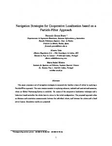
see [3]) to accurately measure those values using GPS, GSM, image sensor and various equipments such as laser scanners together. On the other hand, for pedestrians/bicycles, it is difficult to accurately measure the information on position, velocity, and moving direction since GPS installed in a cell phone is not very accurate and the accuracy decreases to a great extent near a tall building, or under an overhead road/railway where the GPS signal is difficult to be received. Moreover, since the battery amount of a cell phone is limited, frequent and long term measurement is not realistic. Therefore, we need a method to complement GPS-based measurement of positions of the pedestrians/bicycles. In this paper, we suppose a situation that there are vehicles with car computers, roadside devices, pedestrians with mobile terminals which are capable of exchanging data with short range wireless communication. This situation allows us to estimate the pedestrian position based on Trilateration by radio signal strengths (from the pedestrian) received by roadside devices and cars whose accurate positions are known. Assuming several anchors (in-vehicle and roadside devices knowing their accurate positions) around a region near an intersection (Target region) and each pedestrian/bicycle is equipped with a small terminal which periodically emits a beacon signal, we propose a method to estimate the trajectory (position, velocity, direction) of pedestrian/bicycle from the received signal strength (RSS) of beacon messages received at anchors. The situation is shown in Fig. 1. In the proposed method, we model the variation of RSS of beacons based on the Weibull distribution [4]. Anchors receive the beacon signal and measure its RSS and estimate the trajectory (position, velocity, direction) of the beacon sender based on maximum likelihood estimation method according to the RSS at each anchor and its position information. Our method is a range-based localization method. In general, range-based localization may cause big error due to radio wave interference. However, we suppose that there is strong correlation among the RSS subsequently received in a short time interval. Therefore, in our proposed method, we apply the Bayes’ theorem to the measured results to correct the estimation error by analyzing the correlation between positions estimated for different times. As a result, the estimation accuracy is improved. Since our method requires a sufficient number of anchors, we assume that several fixed roadside devices as anchors are deployed near the intersection as shown in Fig. 1. Through computer simulations using RapLab for a typical intersection, we confirmed that our method can estimate
Copyright Ⓒ 2009 IEEE
30-1-2-2 in this research field are classified into range-based methods and range-free methods. Range-based methods [11], [12], [13] estimate the distances between the target object and the anchor nodes by measuring and analyzing the received signal strength, radio propagation time or others, and derive the target object position from the distances, e.g., based on Trilateration. On the other hand, range-free methods [14], [15], [16], [17] do not measure the signal strength, but use the number of hops from the target object to the anchor node to analyze the relative position of the target object. Fig. 1.
Image for Traffic Safety System Using Localization Technology
pedestrian trajectory with much higher accuracy than GPSbased method. II. R ELATED W ORK In this section, first we survey existing Driving Safety Support Systems (DSSS) targeting tracking of pedestrians/bicycles and clearly state the problem that is unsolved. Then, we describe contribution of our proposed method. A. DSSS Targeting Pedestrians/Bicycles There have been proposed some image-processing based DSSS [5], [6], [7]. The advantage of these image-based systems is that the target objects such as pedestrians/bicycles need not be equipped with any special device. However, these systems do not work when obstacles exist between the image sensor and the target object. Localization methods for pedestrians based on GPS [8], [9] have been proposed recently. These methods use GPS modules embedded in cell phones. The advantage of these methods is covering a wide target region. However, the localization accuracy by built-in GPS module of a cell phone is not as good as that by the in-vehicle GPS module with some correction mechanism such as DGPS and Gyroscope sensor. The pedestrian position estimated by built-in GPS module of a cell phone usually has 10 meters error [10], which is critical in the traffic safety system. In an RFID based position estimation method [2], electronic coils generating magnetic fields are embedded in the road, and when a person with an RFID tag passes near a coil, the coil is activated so that the information on the position of the activated coil and the detected tag ID are sent to the nearby vehicles. By this information, the trajectory of a pedestrian/bicycle (velocity, direction, position at each point of time) can be estimated with high accuracy. However, it is too expensive to realize this method because many coils must be embedded in all over the road. The localization method in the research field of the ad hoc network and the wireless sensor network usually assumes that there are anchor nodes which know their accurate positions and a target object whose position is unknown, and estimates the target object position by the anchor positions and some measured information (such as RSS) between the target object and the anchor nodes. The localization methods
B. Contribution of Proposed Method In order to realize DSSS which prevent accidents by tracking pedestrian positions, the following two problems must be solved: (1) cost problem: the system must be deployed widely with low cost; and (2) accuracy problem: position errors may cause more accidents or make drivers dull. A scalable and inexpensive system that can accurately estimate pedestrian positions is desirable. As a method utilizing the received signal strength and Maximum Likelihood Estimation, in [18], Takashima et al. assumed a situation of indoor man location management. Their study described a possibility of the distance estimation by using the received signal strength by real wireless terminals in an indoor environment. Moreover, in [19], Proakis showed that the receiving power (signal strength) distribution follows the exponential distributions under a multi-fading environment called Rayleigh fading where straight radio wave is sheltered, and a lot of scattered waves are received. In this paper, we target an intersection surrounded by buildings. This situation is similar to the indoor Rayleigh fading environment, where the straight radio wave is sheltered by buildings, and a lot of reflection waves are generated by obstacles. We model the received power variation by Weibull distribution [4] to reproduce the Reyleigh fading environment. Moreover, in order to track a fast moving object such as a bicycle, we use Maximum Likelihood Estimation method to derive the trajectory by estimating the object velocity, direction, and position at each point of time. If the velocities estimated at some points of time for a certain time interval are almost identical, the estimated positions are considered to have a strong correlation with each other. By applying the Bayes’ theorem to the obtained trajectory, we can improve the positions in the trajectory. As a result, errors in positions can be reduced. III. P OSITION E STIMATION B Y M AXIMUM L IKELIHOOD E STIMATION In this section, we introduce the outline of Maximum Likelihood Estimation (referred to by MLE, hereafter) method. Then, we introduce how to estimate the movement trajectories (position, speed and direction) of the target pedestrian/bicycle (referred to by target node, hereafter) based on the RSS and MLE method.
Copyright Ⓒ 2009 IEEE
30-1-2-3 A. Outline of Maximum Likelihood Estimation Method MLE is a popular statistical method used for fitting a statistical model to data, and providing estimates for the model’s parameters. Consider a family D of probability distributions parameterized by an unknown parameter θ, associated with every known probability density function, denoted as f (x1 , · · · , xn ; θ). We pick up a sample (x1 , · · · , xn ) of n values from this distribution, and then using f we compute the probability density associated with the sample f (x1 , · · · , xn ; θ). As a function of θ with data x1 , · · · , xn , the likelihood function L(θ) is defined as the following formula (Equation (1)). The method of maximum likelihood finds the value of θ that maximizes L(θ). The maximum likelihood estimator (MLE) of θ is defined as the following formula (Equation (2)). L(θ) = L(θ; x1 , · · · , xn ) = f (x1 , · · · , xn ; θ) (1) θˆ = argmaxθ L(θ)
(2)
If we assume that the data picked up from a particular distribution are independent of each other, then the probability density with data (x1 , ..., xn ) can be calculated by the equation (3), and consequently the likelihood function L(θ) can be calculated by equation (4). n ∏ f (x1 , · · · , xn ; θ) = f (xi ; θ) (3) i=1
L(θ) = L(θ; x1 , · · · , xn ) =
n ∏
f (xi ; θ)
(4)
i=1
Since the value of θ that maximizes L(θ) does not change even when applying monotone transformations, L(θ) can be transformed to equation (5). n ∑ L(θ) = log f (xi ; θ) (5)
(r1 , P1 ), · · · , (rn , Pn ) and equation (8). We let the parameter θ be (β, m), the likelihood function L(θ) be f (z1 , · · · , zn |θ). The parameters β and m in equation (9) can be derived by the MLE method. By using the results from equations (8) and (9), we can model the propagation characteristic of the target region. m f (z) = βmz m−1 e−βz (z ≥ 0; m, β > 0) (9) Furthermore, we note that parameters (C, α, β, m, z) depend on traffic conditions and surroundings. Therefore they may change over time. We will describe the details of the parameters in the next subsection. C. Trajectory Prediction Utilizing RSS We assume that the target node transmits beacon messages periodically while moving, and the beacon messages are received by l anchors. When a beacon message with the sequence number i was received by anchor j located at position (xj , yj ), we denote the RSS at anchor j by Pi,j . (1 ≤ i ≤ n, 1 ≤ j ≤ l) Since we suppose such a situation that a bicycle suddenly rushes into an intersection, we assume that the target node moves along a straight-line. We denote the velocity, the moving direction and the position of the target node by v, a and (x, y), respectively. We denote the time between the reception time of beacon i and the time when the estimation process is conducted as △i. The conditional probability p(Pi,j |v, a, x, y), where the value of Pi,j is known, can be derived from equations (8) and (9). The conditioned probability density p(Pi,j |v, a, x, y) can be solved as follows: xi = x − v∆ti cos(a) yi = y − v∆ti sin(a) √ ri,j = (xi − xj )2 + (yi − yj )2 P¯i,j = Cri,j −α Pi,j zi,j = ¯ Pi,j
i=1
Since equation (5) is a concave down function, we can find θ value that maximizes log L(θ) by solving equation (6). In case of multiple unknown parameters Θ = (θ1 , · · · , θk ), we can find Θ by solving equations (7). ∂ log L(θ) = 0 ∂θ ∂ log L(θ) = 0 ∂θi
(1 ≤ i ≤ k)
(6) (7)
p(Pi,j |v, a, x, y) = f (zi,j ) = βmzi,j m−1 e−βzi,j
m
Here, we denote the RSS of beacon i received by anchor j by the probability variable Xi,j . Since we assume that X1,j , · · · , Xn,j are independent, we may apply the MLE method to solve the following likelihood function (10) with parameter θ = (v, a, x, y). L(θ) = p(P1,1 , · · · , Pn,l |θ) =
n ∏ l ∏
p(Pi,j |θ)
(10)
i=1 j=1
B. Propagation Model in Target Region In the target region, for each packet reception at the receiver, correlation between the sender-receiver distance r and the average RSS P¯ is denoted as equation (8). We measure pair (r, P ) for multiple packet receptions, and decide the parameters C and α for equation (8) by the least square method. P¯ = Cr−α (8) We assume that z = P/P¯ follows the Weibull distribution (equation (9)), and z1 , · · · , zn can be derived from samples
D. Error Correction By Bayes’ Estimation MLE method is useful to estimate independent events such as position estimation by the RSS. However, the error correction is impossible once the estimation is derived even when correlative data are newly obtained. For this reason, the estimation result of the target node trajectory may warp due to the error. Bayes’ theorem is effective to estimate the occurrence probability between multiple correlative events. In the proposed method, we apply Bayes’ theorem to a series of
Copyright Ⓒ 2009 IEEE
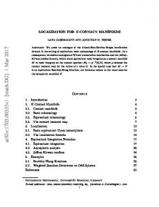
30-1-2-4 the distribution of the conditional probability density for B derived by the estimation method described above. IV. A SSUMPTIONS AND P ROTOCOL D ESIGN In this section, we describe the assumptions and protocol implementation of the method in Section III. In our protocol, considering the limited battery amount of the pedestrian’s device, we assume that the position estimation algorithm is executed by anchors. A. Preliminaries Fig. 2.
The Result on P os.b of Log-Likelihood function
estimated positions to correct the error by investigating the mutual correlation between the positions. As a result, the estimation accuracy can be improved. In Bayes’ estimation, P (B) represents the occurrence probability of event B, called prior probability of event B, and P (B|A) represents the occurrence probability of event B after the occurrence of event A, called posterior probability of event B to A. When applying Bayes’ estimation to the result derived by the MLE method, occurrence of event A must be an earlier estimated position and that of B must be the next estimated position to A. P (B) and P (A) can be derived by the MLE method as the likelihood function. Our goal is to derive P (B|A) and P (A|B) that are the occurrence probabilities of events B and A correlative to each other. The posterior probability of event A to B, P (A|B) can be denoted as equation (11) and P (B|A) can be denoted as equation (12). P (B|A)P (A) P (A ∩ B) P (A|B) = = (11) P (B) P (B) P (A|B)P (B) P (A ∩ B) P (B|A) = = (12) P (A) P (A) Based on Bayes’ theorem, the equations (11) and (12) hold under the condition P (A) > 0 and P (B) > 0. To utilize Bayes’ estimation in our method, when we derive the results of position estimation by MLE method such as P os.b and P os.a, we suppose the estimation processes for P os.b and P os.a as the events B and A in Bayes’ estimation. ZoneP os.b is referred to as the set of possible positions in event B at time t. The probability for each position in ZoneP os.b is denoted by P (B). The image for ZoneP os.b , P os.b and P os.a is shown in Fig. 2. ZoneP os.a is referred to as the set of possible positions in event A at time t − 1 since A is estimated earlier than B, the probability for each position in ZoneP os.a is denoted by P (A). Therefore, our target is to derive the position (xB , yB ) in ZoneP os.b and xA , yA in ZoneP os.a that maximize the P (B|A) and P (A|B) respectively. These two positions are derived as the estimation results with the highest correlation. Since the maximum estimation error in MLE method is more than 3m (See experimental results in Sec. V), we use an circular area centered at estimated result B with a 4 meter radius as shown in Fig. 2 as ZoneP os.b . Fig. 2 is
Target node: Mobile terminal kept by users Each target node has a unique identifier (hereafter, referred to as ID), and sends beacon messages periodically. Each beacon message is sent with almost the same transmission power from all target nodes. Anchor: Road-side fixed infrastructure Each anchor knows its accurate position information, and this information can be used in the estimation process. Each anchor can receive the beacon messages from each target node if they are in their common radio range. The anchor can also obtain the RSS of each received message. In this research, we assume that one of the anchors works as a sink node which conducts the proposed estimation method, and that all anchors can transfer information of the measured RSS and the target ID to the sink node. The sink node estimates the trajectories of all target nodes in the target region (intersection), and it also knows the constant parameters on the variation of average RSS associated with the distance, such as C and α in equation (8). Each anchor has a wired or wireless connection to the sink node. B. Protocol Description The protocol is as follows. 1) Each target node sends beacon messages periodically. 2) Each anchor measures the RSS of each received beacon message, and sends the measured information and its own position information to the sink node. 3) The sink node estimates the trajectories of all target nodes utilizing the information from anchors. Anchor’s activity When an anchor receives a beacon message from a target node, the anchor immediately sends to the sink node a message including the target node’s ID, the reception time, the RSS and the anchor’s position information. Sink node’s activity The sink node estimates trajectories of all target nodes in the region based on the information sent from anchors. C. Requirements adapting to real environment Since our method is based on trilateration, at least 3 anchors are necessary to conduct our method. We assume that a vehicle is considered to be an anchor, so higher vehicle density means larger number of anchors. Therefore, the heavier the traffic situation is, the more accurate estimation is expected.
Copyright Ⓒ 2009 IEEE
30-1-2-5
Case 2 Manhattan Form Fig. 4. Fig. 3.
•
An Image for Considered Region
We deploy anchors at a short interval. The reduction degree of RSS gets larger when the distance between a sender and a receiver gets shorter. According to the above discussion, assuming the RSS with a uniform error, we conclude that shorter distance between a sender and a receiver may lead to a smaller error. We may also consider to use moving anchors. However, the estimation error cannot be in control due to Doppler effect. For this reason, we assume the anchors in proposed method to be fixed infrastructures or stopping cars. V. E XPERIMENTAL VALIDATION THROUGH C OMPUTER S IMULATION In order to evaluate the performance of the proposed method, we conducted computer simulation. A. Configuration for Simulation Environment The supposed situation is listed as follows: The intersection consists of two rectangular crossing roads. The width of each road is 20m. The target region is the 20m×20m square adjacent to the overlapping area of the two roads as shown in Fig. 3. The target node (pedestrian/bicycle) crossing this region broadcasts beacon messages including its ID every 0.2 second. An anchor is deployed at each corner of the target region, so that there are 4 anchors in the intersection. An image for the target region is shown in Fig. 3. The anchors are set at positions A(110, 110), B(110, 90), C(130, 110) and D(130, 90). A sink node connects with each anchor by wired connection and knows their accurate positions. We assume that there are no communication delay and packet loss between the sink node and anchors. The purpose of this experiment is to evaluate the estimation result by RSS of each beacon message rather than to evaluate the protocol efficiency in the wireless network, such as the packet collision in the target region. Therefore, only one target node is set up in the target region at one time. In experiment, we supposed the following three kinds of the intersection forms. • Square form (Case 1) No obstacles exist in the target region and the radio interference is minimum.
•
Case 3 Normal Form
Intersection Forms
Manhattan form (Case 2) All the intersections and roads are surrounded by buildings. Radio wave will be reflected among bumps and buildings. This form is regarded as the maximum electric radio interference situation. This case is shown in Fig. 4 (Case 2). Normal form (Case 3) It is a common situation in the real world. The intersection is not fully surrounded by obstacles. The expected interference is somewhere in between case 1 and 2. This case is shown in Fig. 4 (Case 3).
We observed the following metrics respectively in these three cases. 1) The signal power characteristics of radio propagation The result shows the expected difference of radio propagation in the three different target regions. 2) The position estimation utilizing MLE method The target node position is estimated by MLE method. Since correlation is not considered in MLE method, the error of estimated position will be large. 3) The correction by Bayes’ theorem After applying Bayes’ theorem to the result in MLE method, the error is corrected by analyzing the correlation between subsequently estimated positions. Our simulation system consists of 2 parts: (1) communication/computing part and (2) RSS measurement part. •
•
The communication/computing part We implemented an application on network simulator GT N etS [20] as the communication/computing part. It processes and outputs data above MAC layer such as the target node mobility (uniform velocity straightline motion, 4m/s), time and position at which the node sends/receives beacon messages, the node position estimated by MLE, and the position corrected by Bayes’ theorem. The RSS measurement part This part measures the RSS at each anchor based on the output from the communication/computing part. We use a radio propagation analyzing simulator RapLab[21] based on 3D ray trace method as the RSS measurement part. The ray trace method can analyze radio propagation characteristic such as the propagation loss, delay and incoming direction by tracing the radio wave from a sending point to a receiving point based on Geometrical
Copyright Ⓒ 2009 IEEE
30-1-2-6 ∆TEst (Estimate interval) ∆TBeacon (Beacon sending interval) Dulation(usable beacon log) Used bandwidth Sending Power Receiving threshold PHY& MAC
1 sec. 0.2 sec. 2 sec. 2.4GHz 1mW(0dBm) -68dBm IEEE802.11
Case.1 Case.2 Case.3
TABLE I PARAMETER C α m β
Case 1 0.00006223 1.866 1.764 0.5422
CONFIGURATION
Case 2 0.00006070 1.859 1.146 0.5715
Case.1 Case.2 Case.3
Case 3 0.00006288 1.868 1.629 0.5459
Average Estimation Error Position(m) Velocity(m/s) Direction(deg) 1.14 0.25 40.7 2.29 0.33 40.9 1.35 0.17 42.5 Maximum Estimation Error Position(m) Velocity(m/s) Direction(deg) 1.77 1 180 3.64 2.5 158 2.46 1 180
TABLE III T HE AVERAGE AND M AXIMUM E STIMATION E RROR B Y MLE
TABLE II T HE PARAMETERS IN E ACH C ASE
Optics theorem. To measure the RSS, we configured that the number of reflection is no more than 3 times, the number of diffraction is no more than 1 time as the radio propagation parameter. Also, the antenna is supposed to be omnidirectional. The height of anchor antennas and pedestrian’s terminal are all set at 1 meter above the ground. The position information is represented by two dimension coordinates as (x, y). The configuration of parameters is shown in Tab.I. Simulations were conducted by the following steps: 1) Run the communication/computing part on GT N etS, output the position where a beacon signal is sent and received. 2) Run the RSS measurement part to analyze the RSS based on the output of the 1st step. 3) Run the communication/computing part to estimate the target node position based on the result of the 2nd step. 4) Run the communication/computing part to correct the position estimated in the 3rd step by applying Bayes’ theorem. B. Evaluation Experiments Result 1: The signal power characteristic of radio propagation First of all, the propagation characteristics are different among situations. A set of 820 samples of RSS and sender/receiver distance were measured. The parameters in each case are shown in Tab. II and Fig. 5. Weibull distributions for three cases are also shown in Fig. 5. The vertical line is the histogram of z = P/P¯ , and the interval is 0.1. The average RSS in each case (C, α) has no obvious difference. In addition, the variation of the RSS within 10m range is small. It is considered that all nodes can see each other in all the cases. However, RSS decreases sharply when the sender-receiver distance is extended to 20m or 40m. It is due to the multipath fading effect. In case 2 and case 3, the instability of the RSS becomes remarkable due to the reflection wave by the buildings (obstacles). It is more obvious in case 2. A lot of waves are reflected by the buildings. The parameters on Weibull distribution
METHOD
are different from each other. Where the reflection waves are remarkable in case 2, the parameter m on Weibull distribution is close to 1 in case 1, which shows Rayleigh fading environment-like propagation characteristic. Furthermore, the RSS becomes significant unevenness in the case of long sender-receiver distance. With longer distance, the signal gets more interference. The receiving sensitivity is set to -68dBm in this evaluation. From the average RSS observed, the reasonable communication range is regarded to be less than 25m. However, due to the different interference, we can have a stronger signal than the threshold (-68dBm) in some spot farther than 30m and we may have weak signals in some place even less than 20m. Result 2: The position estimation utilizing MLE method The estimation results in each case are shown in Fig. 6. The average estimation error and the maximum estimation error are shown in Tab.III. For the road width and the interval of anchors are within 20m, the maximum estimation error is about 3.6m. It is accurate enough to judge on which side the pedestrian/bicycle is. However, to provide a DSSS service, the estimation error is still large. The estimated direction in the result is not very accurate, especially when the time of x = 130. This is the time that the target node enter the target region. That phenomenon may be caused by the interference from reflection waves. For example, when the target node is moving from a spot (134, 92) (outside of the region) to (130, 92) (in the region), the distance to anchor A is from 30 m to 26m, while the distance to anchor B is from 24 m to 22m. As a result of propagation characteristic shown in Fig. 5, it is clear that the RSS tends to be stronger than average value when the sender-receiver distance is about 30 m. While the RSS tends to be weaker as the distance changes from 24 m to 22 m. We see that the sink node regarded that the target node is moving closer to A and away from B. As a consequence, an estimation error occurred on the target node moving direction. To avoid this problem, one solution is to increase the number of anchors, but it is costly. Moreover, the reflection waves caused by the structures/obstacles affect the estimation because the received signal changes significantly.
Copyright Ⓒ 2009 IEEE
30-1-2-7 Signal Strength (dBm)
-40
0.8 Samples Estimation Result
-45
Samples Estimation Result
0.7
-50
0.6
-55
0.5
-60
0.4
-65
0.3
-70 -75
0.2
-80
0.1
-85
0 0
10
20
30 40 50 Distance (m)
60
70
80
0
2
Signal Strength (dBm)
0.5 0.45 0.4 0.35 0.3 0.25 0.2 0.15 0.1 0.05 0
Samples Estimation Result
-60 -70 -80 -90 -100 -110 10
20
30 40 50 Distance (m)
10
60
70
80
Samples Estimation Result
0
2
4
6
8
10
z
Case.2 Average RSS
Case.2 Weibull Distribution
-40 Signal Strength (dBm)
8
Case.1 Weibull Distribution
-40
0
6 z
Case.1 Average RSS -50
4
0.6 Samples Estimation Result
-50
Samples Estimation Result
0.5
-60
0.4
-70
0.3
-80
0.2
-90
0.1
-100
0 0
10
20
30 40 50 Distance (m)
60
70
80
0
4
6
8
10
z
Case.3 Average RSS Fig. 5.
2
Case.3 Weibull Distribution
The Characteristics of Radio Propagation in Each Case
In the evaluation, the beacon message broadcasting interval δTBeacon and the time duration of beacons received in the past Duration are fixed. If the target node broadcasts beacon messages by a shorter interval, the estimation accuracy may be increased but the target node battery will be consumed quickly. Furthermore, if Duration is extended, the number of beacons used in estimation will greatly increase, which may lead to a higher estimation accuracy but the response time may become longer. Result 3: The error correction by Bayes’ theorem As described in Sec. 3.D, the estimated result by MLE method is independent. The correlation between neighboring positions is not considered, and the estimated trajectory may be warped. We noticed these problems in MLE’s results which are shown in Fig. 6 and Tab. III. Bayes’ estimation was applied to every neighbor pair of the positions estimated by MLE method in both ascending
and descending order respectively. To correct the error in the positions, the velocity and direction were recalculated. The new result is shown in Fig.6 and Tab.IV. By considering the correlation between neighborhood nodes in this phase, both average error and maximum error are reduced. The average error in each case was reduced by 0.11m, 0.83m and 0.28m, and the maximum error was reduced by 0.14m, 1.44m, 0.83m respectively. Especially, the maximum error in case 2 was reduced to 2.20m at this time, which seems a reasonable accuracy to identify the target node in real traffic environment. The error on moving direction of the result in MLE method was very large since the estimation for each position is independent. According to the correlation of neighborhood positions, the accuracy of moving direction was improved significantly. By the error correction process, the trajectory of the target node was derived with a reasonable accuracy.
Copyright Ⓒ 2009 IEEE
30-1-2-8
Fig. 6.
Case.1 Case.2 Case.3
Case.1 Case.2 Case.3
Estimated Result by MLE and Bayes’ estimation Average Estimation Error Position(m) Velocity(m/s) Direction(deg) 1.03 0.25 7.7 1.46 0.25 4.77 1.07 0.17 10.3 Maximum Estimation Error Position(m) Velocity(m/s) Direction(deg) 1.63 1 11 2.20 2 12 1.63 1 22 TABLE IV E RROR CORRECTION BY BAYES ’ THEOREM VI. C ONCLUSION
In this paper, we proposed a pedestrian/bicycle trajectory estimation method for preventing the vehicle vs. pedestrian/bicycle accident at intersections. We modeled the variation of RSS at anchors by Weibull distribution. In our method, the pedestrian terminal broadcasts beacon messages periodically, and the anchors measure the RSS of the messages when they are received. By analyzing the RSS utilizing the Maximum Likelihood Estimation, we can derive the trajectory of the target node. Moreover, we applied Bayes’ theorem to improve the estimation accuracy. We conducted computer simulations where we modeled 20m × 20m square area on the road near an intersection as a target region where 4 anchors were deployed at the corners of the area. As a result, the maximum estimation error was about 4m, the average estimation error was about 1m. We believe that these results show that our method has applicability to an actual driving safety support system that handles the moving trajectory of pedestrians/bicycles on road. We note that radio interference and message collision must be considered if we deal with multiple targets in the same intersection. This is a part of our future work. R EFERENCES
the 12th World Congress on ITS, pages 1 – 11, 2005. [2] Hideo Oda, Soichi Kubota, and Yoshiharu Okamoto. Study of how to notify the warning information such as pedestrian’s position, direction and speed to the driver, in safety driving support system using rfid. The Papers of Technical Meeting on Intelligent Transport Systems, IEE Japan, 2006(103):31 – 36, 2006. [3] Robin Schubert, Marius Schlingelhof, Heiko Cramer, and Gerd Wanielik. Accurate positioning for vehicular safety applications the SAFESPOT approach. In Proceedings of the IEEE Vehicular Technology Conference (VTC 2007-Spring), pages 2506 – 2510, 2007. [4] Goran W. Weibull. A statistical distribution function of wide applicability. J Appl Mech, pages 293 – 297, 1951. [5] Pietro Cerri, Alberto Broggi, Luca Gatti, Paolo Grisleri, and Hogi Jung. Scenario-driven search for pedestrians aimed at triggering nonreversible systems. In Proceedings of 2009 IEEE Intelligent Vehicles Symposium (IV ’09), page In DVD, 2009. [6] Huijing Zhao, Long Xiong, Zhigang Jiao, Jinshi Cui, and Hongbin Zha. Sensor alignment towards an omni-directional measurement using an intelligent vehicle. In Proceedings of 2009 IEEE Intelligent Vehicles Symposium (IV ’09), page In DVD, 2009. [7] ndreas Wimmer, Thorsten Weiss, Francesco Flogel, and Klaus Dietmayer. Automatic detection and classification of safety barriers in road construction sites using a laser scanner. In Proceedings of 2009 IEEE Intelligent Vehicles Symposium (IV ’09), page In DVD, 2009. [8] Motilal Agrawal and Kurt Konolige. Real-time localization in outdoor environments using stereo vision and inexpensive gps. In Proceedings of the 18th International Conference on Pattern Recognition (ICPR 2006), pages 1063 – 1068, 2006. [9] F. Chausse, J. Laneurit, and R. Chapuis. Vehicle localization on a digital map using particles filtering. In Proceedings of IEEE Intelligent Vehicles Symposium, pages 243 – 248, 2005. [10] Koichiro Meguro and Hirofumi Suzuki. Development of a new solution using the gps-enabled mobile phone. Research paper, Mitsubishi Research Institute, Inc, 2007. [11] Paramvir Bahl and Venkata N. Padmanabhan. RADAR: An in-building RF-based user location and tracking system. In Proceedings of the International Conference on Computer Communications (INFOCOM 2000), pages 775 – 784, 2000. [12] N. B. Priyantha, A. Chakraborty, and H. Balakrishnan. The cricket location-support system. In Proceedings of the 6th Annual International Conference on Mobile Computing and Networking (MobiCom ’00), pages 32 – 43, 2000. [13] Dragos Niculescu and Badri Nath. Error characteristics of ad hoc positioning systems (APS). In Proceedings of the 5th ACM International Symposium on Mobile Ad Hoc Networking and Computing (MobiHoc 2004), pages 20 – 30, 2004. [14] Dragos Niculescu and Badri Nath. Ad hoc positioning system (APS). Proceedings of the IEEE Global Telecommunications Conference (GLOBECOM 2001), pages 2926 – 2931, 2001. [15] R. Nagpal, H. Shrobe, and J. Bachrach. Organizing a global coordinate system from local information on an ad hoc sensor network. In Proceedings of the 2nd International Workshop on Information Processing in Sensor Networks (IPSN ’03), pages 333 – 348, 2003. [16] Sungwon Yang, Jiyoung Yi, and Hojung Cha. HCRL: A hop-countratio based localization in wireless sensor networks. In Proceedings of the International Conference on Sensor, Mesh and Ad Hoc Communications and Networks (SECON ’07), pages 31 – 40, 2007. [17] S. Guha, R. Murty, and E. G. Sirer. Sextant: A unified node and event localization framework using non-convex constraints. In Proceedings of the 6th ACM International Symposium on Mobile Ad Hoc Networking and Computing (MobiHoc 2005), pages 205 – 216, 2005. [18] Masahiro Takashima, Dapeng Zhao, Kentaro Yanagihara, Kiyoshi Fukui, Shigeru Fukunaga, Shinsuke Hara, and Kenichi Kitayama. Location estimation using received signal power and maximum likelihood estimation method in wireless sensor networks. The IEICE transactions on communications. B, J89-B(5):742 – 750, 2006. [19] John G. Proakis. Digital Communications (3rd ed.). Singapore: McGraw-Hill Book Co., 1995. [20] GTNetS -Home. http://www.ece.gatech.edu/research/ labs/MANIACS/GTNetS/. [21] RapLab, radio propagation labortaory. http://www4.kke.co. jp/raplab/.
[1] James A. Misener and Raja Sengupta. Cooperative collision warnig: Enabling crash avoidance with wireless technology. In Proceedings of
Copyright Ⓒ 2009 IEEE