The International Journal of Advanced Manufacturing Technology https://doi.org/10.1007/s00170-018-2736-9
ORIGINAL ARTICLE
Rapid casting of complex impeller based on 3D printing wax pattern and simulation optimization Donghong Wang 1,2 & Anping Dong 1,2 & Guoliang Zhu 1,2 & Da Shu 1,2,3 & Jinyu Sun 4 & Fei Li 1,2 & Baode Sun 1,2,3 Received: 3 April 2018 / Accepted: 17 September 2018 # Springer-Verlag London Ltd., part of Springer Nature 2018
Abstract Rapid casting is the product of digital, information, and optimization of casting technology. It mainly includes rapid prototyping and virtual manufacturing. In order to shorten the production cycle of a stainless steel closed impeller casting, the wax pattern was made by high impact polystyrene (HIPS) with a selective laser sintering and photosensitive resin with stereolithography (SL). In order to prevent the formation of shrinkage defects, different gating systems designed to examine the molten metal flow and solidification behavior during the pouring and solidification process. The results show that pouring temperature is 1550 °C and pouring speed is 0.75 m/s, which is favorable for filling impeller castings, and can avoid casting defects. The optimized gating system prevented surface shrinkage and interior defects. The optimized gating systems have been verified by experiment, and the rapid casting has been realized based on 3D printing wax pattern and simulation optimization. This rapid casting can reduce processing time and costs, and enhance casting quality in the foundry industry. Keywords Rapid casting . Stainless steel impeller . Shrinkage porosity . Numerical simulation . Rapid prototyping
1 Introduction With the development of new 3D printing technology, numerical simulation, and artificial intelligence technology, casting production is moving from relying mainly on experience to
* Anping Dong
[email protected] Guoliang Zhu
[email protected] Fei Li
[email protected] 1
Shanghai Key Lab of Advanced High-temperature Materials and Precision Forming, School of Materials Science and Engineering, Shanghai Jiao Tong University, 800 Dongchuan RD, Minhang District, Shanghai 200240, China
2
State Key Laboratory of Metal Matrix Composites, School of Materials Science and Engineering, Shanghai Jiao Tong University, Shanghai 200240, China
3
Materials Genome Initiative Centre, School of Materials Science and Engineering, Shanghai Jiao Tong University, Shanghai 200240, China
4
School of Materials Engineering, Shanghai University of Engineering Science, Shanghai 201620, China
scientific theory [1–3]. The major steps include injection molding of a wax pattern, ceramic, shell building, dewaxing, drying, and metal casting in investment casting. The traditional wax patterns of investment casting are usually prepared by metal mold which has very high cost and is time-consuming. Presently, almost all commercialized additive manufacturing (AM) techniques have been employed to produce investment casting patterns with varying success [4–6]. The rapid prototyping technologies of wax pattern in investment casting mainly include laser selective sintering (SLS), light curing forming (SLA), and polymer spray forming [5–9]. Direct metal printing can build a dense part and eliminate the need for a mold or a long casting process [3]. The cost of metal powder, the processing cost of 3D printing, and the relatively slow processing speed are all disadvantages of metal additive manufacturing. In addition, metal 3D printing finishing also needs manual operation and is labor-intensive work. All of these factors will eventually result in the average cost of 3D printed metal parts being maintained at a relatively high level. A wide range of materials can be used as the wax pattern in SLS, such as nylon, photosensitive resin, polystyrene, and acrylonitrile butadiene styrene. However, some problems must be considered when selecting a material. It is found that high impact polystyrene (HIPS) shown to be more suitable for investment casting applications [4, 10]. Definitely, there are
Int J Adv Manuf Technol Fig. 1 Solid model and shape dimensions of the enclosed impeller
still some problems for rapid prototyping patterns used in investment casting due to high-melting temperature and high-melting viscosity of polymer. The ceramic shell cracking during the burnout process in investment casting with internally webbed laser stereolithography patterns is one [5, 9]. The traditional manufacturing line relies heavily on the tedious hit-and-trial method to get the defect-free casting. Numerical simulation methods are widely utilized to optimize the temperature field, solidification defects and increase the yields of cast parts during the casting process [11–13]. It is reported that about 90% of the defects in castings are due to wrong design of gating and risering system, and only 10% due to manufacturing problems. The gating system usually consists of a pouring cup, gate, runner, and riser. With the aid of parametric modeling technology, the runner and riser are modeled parametrically. Using simulation method, the shrinkage defects can be forecast efficiently with a quantitative level [14]. It is easy to get the most suitable runners and risers with different casting by the simulation results [15]. Huang predicted the solidification processes and casting defects in the highspeed rotor of hemodialysis machines by using AnyCasting software [16]. The shrinkages at the joint between axle head and the main body of the impellor can be eliminated by modifying the original process [17]. Inappropriate design of gating system will cause filling-related defects such as shrinkage cavity and surface roughness. The most likely position of the
shrinkage porosity can be predicted in the investment casting process. This research studies the feasibility of rapid casting for a complex impeller based on 3D printing wax pattern and gating system optimization. The rapid prototyping patterns were made by photosensitive resin and HIPS. Through computerassisted, four concepts of the gating system were designed. The evolutionary process of metal flow and solidification behaviors were analyzed to acquire the optimized gating system and prevent possible casting defects in the complex impeller.
2 Experimental and numerical methods 2.1 Geometric model and materials properties The investment casting process of enclosed impeller was investigated in this study. The solid model of the impeller is shown in Fig. 1a. The 3D geometry dimensions of the impeller are shown in Fig. 1b. The casting material is 304 stainless steel. The impeller is mainly composed of three parts: front cover plate, blade, and back cover plate. There are 17 blades with a thickness of 2 mm and the maximum diameter is 254.2 mm, as shown in Fig. 1. The impeller structure is complicated, especially in radial and axial twisting of centrifugal pump blade. The wax pattern of impeller needs to be assembled with the three parts: front cover plate, blade, and back cover plate. The wax injection of impeller will lead to a long development time in investment casting. The physical properties of the 304 stainless steel were calculated by JMatPro software and then were imported into ProCAST to make the simulation results more accurately. The thermal conductivity, specific heat capacity, and enthalpy with temperature of the steel are shown in Fig. 2.
2.2 Rapid prototyping of wax patterns
Fig. 2 Thermophysical properties of 304 stainless steel
As to verify the feasibility and evaluate the dimensional accuracy of two rapid casting solutions based on 3D printing technology, the rapid prototyping of wax
Int J Adv Manuf Technol Fig. 3 The rapid prototyping of wax patterns using photosensitive resin and HIPS
patterns 3D printing by photosensitive resin and HIPS SLS pattern infiltrating with wax are shown in Fig. 3. The experimental equipment is an HRPS laser forming machine of Huazhong University of Science and Technology. In order to save material, improve printing speed and dilatation and crack of shell during dewaxing process, the optimum design of impeller model was carried out with shell extraction. Figure 3a shows the optimized impeller model for shell extraction, in which the thickness is 0.8 mm. After multi-layer stucco ceramic shell was developed, stereolithography (SL) pattern needed to be removed from the shell. During the SL pattern removal process in either furnace or autoclave, the thermal expansion of the pattern tended to induce significant stress in the shell which could cause the shell cracking. The photosensitive resin pattern has fine surface quality. The ceramic shell made by photosensitive resin was cracking during dewaxing process with increasing the temperature to 200–250 °C in this experiment. The incomplete pattern burning out and residual ash have been observed and reported by various researchers during the use of photosensitive resin pattern [9]. It can be concluded that photosensitive resin is not
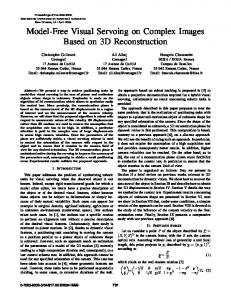
Fig. 4 Design diagrams of four gating systems; a–d cases 1–4, respectively
suitable for rapid casting for impeller castings with complex internal structure.
2.3 Gating system designs and simulation parameters In order to eliminate shrinkage and porous defects in the impeller, bottom, top, and side gating systems with different pouring parameters were used to examine flow and solidification behavior in investment casting. Four gating system schemes were sequentially designed (cases a–d shown in Fig. 4a–d, respectively). The top pouring system is shown in Fig. 4a, c. Risers were also placed on the center of the impeller to serve as feeders. Riser acts as reservoirs to feed molten metal to the shell cavity to avoid solidification shrinkage. Hence, the riser is designed to solidify after the feeding process. For the purpose of easy dewaxing of 3D printing model, two wax discharge channels have been installed on the surface of front cover plate. A spherical riser was added in the middle of the vertical sprue for better heat storage and enhanced capacity for feeding. Figure 4b, d shows that the pouring system is designed on the back center of impeller. Two wax discharge channels were added at the front cover plate, as shown in the
Int J Adv Manuf Technol
Fig. 5 The evolution of the fling state in the blades with the four gating systems
Fig. 4d. Large intermediate sprue enhances the feeding capacity of the gating system for the case d. The setting of boundary conditions and the select of material thermal parameters are closely related to the accuracy of numerical simulation of the casting process. Pouring velocity and pouring temperature was 0.75 m/s and 1550 °C, respectively, recommended by Zhao, which can avoid the defects of insufficient pouring [18]. The shell preheat temperature was 1000 °C, and the heat transfer coefficient was set as 1000 W/ m2 K. The interface nodes are symmetrical and COINC was used. The cooling condition is air cooling. The thickness of the mold shell is 8 mm and the mold material was refractory mullite. The density is 3150 kg/m3, and the thermal properties are found in the database of ProCAST software.
3 Results and discussion 3.1 Flow analysis for different gating systems The metal flow process has an important influence on the quality and performance of the casting. The flow velocity of metal, the direction of flow, and the temperature have great influence on the filling result. The filling process with different gating systems is shown in Fig. 5a–d, respectively. The blade is the thinnest part of the impeller, also the most difficult parts to fill. This part will focus on the blades filling in the four
different gating systems. After the molten metal is poured into the sprue cup, the liquid metal first fills the entire sprue. As we can see from Fig. 5a and Fig. 5c, it is clearly that the liquid metal filling and flow are not uniform at the same section in the case a and case c. It generated violent splashes and flow instabilities. The metal filling on the blade is uneven, and the intersection of two metal fluids will be generated on the blade. There is a very obvious phenomenon of discontinuous flow appears. That can induce gas bubbles or turbulence formation in shell cavity. The residual gas can lead to the formation of porous defects and oxide inclusions in castings. The molten metal smoothly filled and stability flowing over 17 blades in case b and case d, as shown in Fig. 5b and Fig. 5d. Liquid metal enters the cavity along the runner from the riser. There is a symmetrical filling situation in cases b and d. As shown in Fig. 5d, case d has a good filling and flow situation as well as case b. Liquid metal rises slowly from the bottom of the shell, the filling is smooth, without serious splash and misrun in the filling whole process. The results of mold flow analysis revealed that the pouring approach of case a and case d could effectively eliminate the casting defects.
3.2 Solidification and shrinkage porosity analysis Isolated liquid region refers to the liquid phase can be surrounded by the solid phase. Because of no supplements channel, it will generate shrinkage porosity and can be
Fig. 6 The predicted isolated liquid region with different gating systems; cases a–d, respectively
Int J Adv Manuf Technol Fig. 7 The last solidification region for the case b and case c
intuitively reflect the shrinkage porosity position with a high reference value. The isolated liquid region between 0 and 0.7 fraction solid with different risers is shown in Fig. 6a–d, respectively. The color bar represents the solid-phase fraction, “0” indicates the complete liquid phase, while “1” indicates the complete solid phase. It can be seen that the isolated liquid phase areas exist at in the center of the riser when the casting is totally solidified in the case a and case d from Fig. 6. There is no isolated liquid region in the casting body. It can be concluded the shrinkage cavity transfer from casting to the gating system. However, in cases b and c, the region A and region B are the isolated liquid region in casting, as shown in Fig. 6. As is shown Fig. 6b, c, the isolated liquid phase still exists in the middle of the outer ring cover plate. This region cannot be fed by the risers and shrinkage may occur at those positions due to the feed paths solidified. The hot spots are located in the outer ring wall. The final solidification region is shown as shown in Fig. 7. It can be seen that the metal firstly solidified in the middle of the outer ring cover plate in case b. It is easy to form surface shrinkage cavity in this area. The distribution result of shrinkage porosity for the cases b and c is shown as in Fig. 8. It can be seen that the shrinkage appears at the middle of the outer ring cover plate. The color bar in Fig. 8 represents the percentage of shrinkage. The shrinkage is macroshrinkage when the value is greater than 0.01. The macroshrinkage Fig. 8 The distribution result of shrinkage porosity for the case b and case c
(greater than 0.03) with different risers is shown in Fig. 9a– d, respectively. To the effectiveness of in reducing the probability of shrinkage and porosity formation, there is no shrinkage porosity in the casting body in case a and case d because of spherical feeder has a better thermal storage capacity. So, the results of this assessment of isolated liquid region and shrinkage indicated that case a and case d possess the best overall gating system. The longer solidification time of the feeder is, the better feeding capacity for blades part, it means blades part would be fed better.
3.3 Experimental verification The wax pattern was dipped in the slurry of mixed with silica sol and zircon powder. The sand material used in the surface layer is − 70/+ 200 mesh zircon sand. The mold shell should be placed in the environment of temperature 19–25 °C and relative humidity 50–70% after the surface layer is coated with slurry sand, and the drying can be assisted by electric fan applying 0.5 m/s wind. The drying time is 24 h. The face coats of the shell with a thickness of approximately 5.5 mm are shown in Fig. 10a. The sand material used in the back shell is − 30/50 mesh mullite. Dewaxing was carried out in steam dewaxing kettle after slurry sealing for 24 h. The ceramic shell made by photosensitive resin pattern cracked when the ceramic shell was sintered at 1000 °C in this experiment. The final
Int J Adv Manuf Technol
Fig. 9 The predicted shrinkage with different risers; cases a–d, respectively
Fig. 10 Casting scheme of case d. a Ceramic shell mold. b Impeller product
casting made by the HIPS wax pattern is shown as in Fig. 10b. The accuracy of the actual impeller can be controlled within 100 ± 0.2 mm as the measured diameters. There is no macroshrinkage in the impeller castings with observation, because all four gating systems have a good supplement capacity. For saving materials and energy, we would choose one case as actual production, so we conduct casting yield and shrinkage porosity as chosen criteria. Table 1 shows statistical results of the weight and casting yield calculated by UG software for the four gating systems. The yield of each solution was evaluated as follows: case a (43.26%), case b (52.08%), case c (58.38%), and case d (41.59%). Clearly, case c presented the highest yield at a lower cost with high shrinkage. The results indicate that there is no shrinkage porosity in case a and case d. Case a and case d have little difference in production yield. In order to avoid cracks in the shell during dewaxing, the casting part is made by SLS and the gating system is often Table 1 Case 1 2 3 4
Weight and casting yield of the four gating systems Gating system weight (kg)
Casting yield (%)
12.992 9.114 6.931 13.911
43.26 52.08 58.83 41.59
made of traditional wax. The assistant running channel was also added to accelerate the removal of liquid wax. The results of this assessment reveal that case d possesses the best overall riser system.
4 Conclusions In the current paper, a complex impeller was successfully developed by combining 3D printing wax pattern and simulation optimization. Compared with the conventional investment casting, the new process has a shorter process, a lower product cost, and an appropriate production yield. It is more suitable for new product development and single-piece or small-batch production. The main contributions of this paper are as follows: (1) The rapid prototyping patterns were photosensitive resin and HIPS pattern infiltrating with wax. The ceramic shell was cracking during dewaxing process with photosensitive resin wax pattern. The rapid casting technologies based on 3D printing of HIPS were proved to be effective for the production of impeller. It can be concluded that photosensitive resin is not suitable for rapid casting for impeller castings with complex internal structure from this experiment.
Int J Adv Manuf Technol
(2) Four gating system schemes are designed. The mold filling and temperature field for the enclosed impeller casting were compared. These predicted results can be helpful for the optimal gating location and sizing, location of feeder, or air vents. The predicted isolated liquid region revealed that the configurations of feeder in case b and case c would be unable to eliminate shrinkage defects. The results of this assessment reveal that case d possesses the best overall riser system. (3) 3D printing wax pattern and computer simulation analysis can reach an optimal design thereby reducing shop floor trials. From the discussion, it is obvious that rapid prototyping and simulation be effective for rapid casting. It is the highly advanced manufacturing processes to produce a unit of the final metal casting. Funding information This work was financially supported by The Major State Basic Research Development Program of China (2016YFB0701405) and National Natural Science Foundation of China (51705314, 51771118, U1760110). The authors gratefully acknowledge the financial supports from the National Industrial Basis Improvement Project under Project (TC160A310-12-1) and The 13th Five-year Major Project of Aero Engine and Gas Turbine of China (2017-VII-008). The Science and Technology Committee of Shanghai Municipality (Grant Nos. 16DZ2260602) are gratefully acknowledged. Publisher’s Note Springer Nature remains neutral with regard to jurisdictional claims in published maps and institutional affiliations.
4.
5.
6. 7.
8.
9.
10.
11.
12.
13.
14.
15.
References 16. 1. 2.
3.
Chhabra M, Singh R (2011) Rapid casting solutions: a review. Rapid Prototyp J 17(5):328–350 Collins PK, Leen R, Gibson I (2016) Industry case study: rapid prototype of mountain bike frame section. Virtual Phys Prototyp 11(4):295–303 Wong KK, Ho JY, Leong KC, Wong TN (2016) Fabrication of heat sinks by selective laser melting for convective heat transfer applications. Virtual Phys Prototyp 11(3):159–165
17.
18.
Liu HJ, Fan ZT, Huang NY, Dong XP (2003) A note on rapid manufacturing process of metallic parts based on SLS plastic prototype. J Mater Process Technol 142:710–713 Yao WL, Leu MC (1999) Analysis of shell cracking in investment casting with laser stereolithography patterns. Rapid Prototyp J 5(1): 12–20 Bassoli E, Gatto A, Iuliano L, Violante MG (2007) 3D printing technique applied to rapid casting. Rapid Prototyp J 13(3):148–155 Cheah CM, Chua CK, Lee CW, Feng C, Totong K (2005) Rapid prototyping and tooling techniques: a review of applications for rapid investment casting. Int J Adv Manuf Technol 25(3):308–320 Dotchev K, Soe S (2006) Rapid manufacturing of patterns for investment casting: improvement of quality and success rate. Rapid Prototyping J 12(3):156–164 Chen X, Li D, Wu H, Tang Y, Zhao L (2011) Analysis of ceramic shell cracking in stereolithography-based rapid casting of turbine blade. Int J Adv Manuf Technol 55(5–8):447–455 Yang JS, Shi YS, Shen QW, Yan CZ (2009) Selective laser sintering of HIPS and investment casting technology. J Mater Process Technol 209:1901–1908 Thammachot N, Dulyapraphant P, Bohez ELJ (2013) Optimal gating system design for investment casting of sterling silver by computer assisted simulation. Int J Adv Manuf Technol 67:797–810 Zhou JX, Wang M, Yin YJ, Shen X, Chen X, Li W, Zhang DQ (2017) Feed paths and hot spots computation based on a time gradient method in casting. Int J Adv Manuf Technol 93:261–272 Kuo JK, Huang PH, Lai HY, Chen JR (2017) Optimal gating system design for investment casting of 17-4PH stainless steel enclosed impeller by numerical simulation and experimental verification. Int J Adv Manuf Technol 92:1093–1103 Sutaria M, Ravi B (2014) Computation of casting solidification feedpaths using gradient vector method with various boundary conditions. Int J Adv Manuf Technol 75:209–223 Kuo JK, Huang PH, Guo MJ (2017) Removal of CrMo alloy steel components from investment casting gating system using vibrationexcited fatigue failure. Int J Adv Manuf Technol 89:101–111 Huang PH, Lin CJ (2015) Computer-aided modeling and experimental verification of optimal gating system design for investment casting of precision rotor. Int J Adv Manuf Technol 79:997–1006 Zhi X, Han Y, Yuan X (2015) Casting process optimization for the impellor of 200ZJA slurry pump. Int J Adv Manuf Technol 77: 1703–1710 Zhao J, Yi CL (2015) Optimization of investment casting process for stainless steel impeller with complicated geometry. Chin J Mater Res 29(12):955–960