Rapid Development of Modular Dynamic Web Sites using UML Tim Schattkowsky1, Marc Lohmann2 1 Paderborn
University, C-LAB, D-33102 Paderborn, Germany
[email protected] 2 Paderborn University, Department of Computer Science, D-33095 Paderborn, Germany
[email protected]
Abstract. Development of dynamic Web sites is often performed by teams consisting of graphic designers and software developers. Communication between these different team members has to be supported with a simple modeling approach that considers their different academical backgrounds. Dynamic Web sites can contain multiple modules that may reappear on different pages. Reuse of both business logic and visual design modules would be desirable. Furthermore, a considerable amount of time is usually consumed by the implementation of data flows that are already defined in the model. Rapid development is enabled by providing roundtrip engineering capabilities with support for automatic code generation. We propose a simple subset of the UML adapted to the problem domain by means of stereotypes as well as a strategy for generating code templates from such models. These templates are tailored to the tasks of each team member. This enables parallel work and automated reintegration of results. Keywords: Unified Modeling Language, Hypermedia, WWW, Object-Oriented Design, Code Generation
1
Introduction
There is a growing demand for lightweight methods for the development of smalland medium scale Web applications. Short production time and heavy cost pressure from customers and competitors are major economic factors in the development process of these systems. Heavyweight development processes would introduce expensive overhead into such projects, which cannot be economically compensated by the process’s benefits. The development teams for such Web applications consist of people with different skills and academic backgrounds [10]. These people use different languages to communicate their ideas which leads to misunderstandings. This may cause expensive redesigns. In order to support successful communication, a common language is required, which is understandable to people of different background. The Unified Modeling Language (UML) [3,11] fulfills this requirement by providing a family of
intuitive diagrammatic notations by which a software system can be described at a high level of abstraction. The different views and backgrounds of the team members have to be supported by the models. These models have to be focused on the information relevant to the different roles in the development team. In many cases, we can distinguish between the domain expert, who has knowledge about the business processes behind the Web application, the graphic designer, who is in charge of the creation of the user interface, usually consisting of HTML pages, and the developer, who has to build a working software system based on the work of his partners. Furthermore, we have the customer, who has little knowledge about the technical realization of the project. As a result, another requirement for a Web application engineering methodology is the support for the views and backgrounds of different roles in development teams. On the more technical side, many Web applications are based on dynamic Web pages generated by scripts written in a language like PHP [1], Microsoft’s Active Server Pages (ASP) [9] or Java Server Pages (JSP) [12]. Thus, these Web applications are in fact dynamic Web sites. This introduces a problem into the development process. The responsibilities for the script and the design of the generated pages are split between developer and graphic designer. Furthermore, these scripting languages usually lead to a mixture of business logic and design elements within one software module. This has to be clearly separated into separate modules to allow the reuse of both logic and design modules. The method we propose enforces modularization of Web applications. This enables the team members to work concurrently on different modules of a Web page and to consistently integrate their results. Many small and medium scale Web applications only have small business logic. For such systems, the realization of data input, transport and presentation consumes a considerable amount of production time. A modeling approach for dynamic Web sites should support automatic code generation and thus safe production time. The models should also yield a complete structural description of the Web site. This enables the generation of a working incomplete prototype without design elements and business logic and enables rapid prototyping. Such a prototype allows early demonstrations, which are very important for customer communication. We propose a lightweight UML-based approach to modeling small and medium sized Web applications aiming at the above requirements. The approach employs specific use case diagrams, activity diagrams and class diagrams in order to capture the fundamental structural and behavioral aspects of a Web application while providing different views on these aspects according to the needs of different team members. Using the running example of an online reservation system, we demonstrate the derivation of code templates in HTML and PHP from the models.
2
Related Work
In this section, we briefly discuss different approaches to the modeling of Web applications. Some focus on the modeling notation, like Conallen who proposes an extension to the UML. Other focuses on the development process, for example [2, 7], WebML or WSDM.
Conallen [5] defines a UML profile for Web application design. He introduces stereotypes for components, classes, methods and associations in order to distinguish, for example, server components, client components, server pages, etc. The approach covers the modeling of layout and implementation aspects. However, he does not support modularization besides using frames. Koch and others [2, 7] are describing a hypermedia extension to the UML to model Web applications, focusing on the navigation and the user interface. The conceptual model consists of a class diagram identifying the objects of the problem domain and their relations. The navigation structure is described by a class diagram specifying navigational nodes and links. The presentation model defines the structure of the user interface by means of composite objects and their dynamic behavior by state diagrams. Further, presentation objects are used to describe the concrete layout of the user interface. This approach seems to be oversized for small applications whose interface consists of simple HTML pages. Our modeling approach focuses on those aspects that are important for the cooperation between developers, graphic designers, and domain experts, leaving user interface design and layout to the graphic designer. The Web Modeling Language (WebML) [4] is a notation for specifying complex Web sites at a conceptual level. It distinguishes between a structural model, a composition model, and the topology of links between pages. Further, WebML lets you define layout and graphic requirements for page rendering and includes a personalization model. WebML also addresses the issue of different kinds of specialist playing different roles. WSDM (Web Site Design Method) [6] is a user centered approach. The starting point is a set of potential visitors of a Web site which are classified into user classes. The available data is modeled on the basis of the information requirements of the users. WSDM describes a four phase process: user modeling, conceptual design, implementation design, and implementation. The user modeling phase consists of two sub-phases, the user classification and the user class description. With the user classification the audience of the Web site are identified and classified. Different user classes perform different activities on the Web site. The user class description contains information requirements and the characteristics of the user classes. The conceptual design phase consists of the two sub-phases of object modeling and navigational design. Within object modeling, the information requirements of different user classes with their different perspectives are formalized. How the different users can navigate through the Web site is described within the navigation model. This method defines its own graphical notation for the objects of the navigation model and does not distinguish different views for designer and application developer.
3
Design Methodology
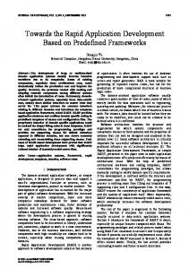
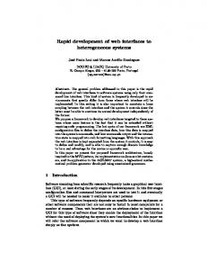
3.1 A Conceptual Model for Web Applications Small and medium size Web applications usually are based on dynamic Web pages using server side scripting. Fig. 1 shows a simple abstract model for such Web
applications. All interactions in these Web applications are based on Web pages. We have to distinguish between a client page and the server page generating the client page. Static and dynamic Web pages are usually distinguished. For a static page, the client page is a simple client side copy of the server page. In the case of a dynamic page, a server side program is computing the client page. A dynamic page is usually implemented using some scripting language like PHP, JSP or ASP. This script generates the client page to be displayed by the client. For Web applications, all Web pages can be regarded as dynamic pages, since a static page is a special case of a dynamic page. Hence, we do not have to distinguish between static and dynamic pages in our model. Client ClientPageModule consists of
LogicInterface
Server ClientPage
DesignElement
Serv erPage
generates 0..n
1
0..n
0..n
BusinessLogic «use»
Hyperlink
DesignTemplate «use»
Fig. 1: Abstract Model of Web applications Client pages consist of different modules. These modules are either pure design elements or logic interfaces. Such logic interfaces enable the user on the client side to interact with the server side business logic. The interaction between the client and the server is achieved through hyperlinks. The activation of such a hyperlink may also cause the transmission of data from the client to the server, i.e., as HTML form data (“post”) or URL-encoded (“get”). This data is used by the server page to compute a new client page. Thus, the business logic is contained in the dynamic pages on the server side. These pages also have design templates that define the visual appearance of the client page. A client page may contain hyperlinks to different server pages. While this model captures dynamic Web sites at a high level, it is not precise enough to support the development process and overcome common problems. Currently, many small- and medium size Web systems suffer from the mix of presentation and business logic in the code modules. These systems are implemented very straightforwardly using monolithic scripts, but certain parts of the business logic and the design are relevant for more than one server page and should be reused. Let us consider the example of a hotel reservation system where a business logic module computes the price for a room reservation. This module may be relevant for both a server page offering to place the reservation as well as for verifying the validity of the price of a confirmed reservation when booking this reservation. This raises the need for reuse of the business logic. Such a reuse is common sense for normal software development. For Web application development, this is still an important issue [8]. Our model supports the reuse of logic modules, because a logic module may be associated to multiple server pages. In our example, the module implementing the logic for computing the price for a reservation would be associated to both server pages mentioned above. We consider a Web page as a composition of reusable modules. From the model in Fig. 1 we can derive two kinds of modules. The logic module encapsulates a part of
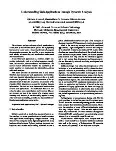
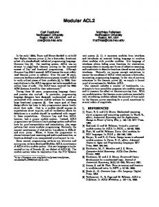
the business logic while the design module represents a reusable part of the design template. These modules have both client side (client page module) and server side (server page module) representations. The client side subtypes of these modules are the design element representing a reusable design module and the logic interface representing the interface of a logic module. Since the logic modules in our model are also responsible for the generation of client page modules, they still combine logic and presentation. We have to decompose these logic modules into smaller modules (see Fig. 2). This allows us to encapsulate and separate these two aspects. Thus, we achieve a separation of the business logic and the presentation of the computed data. The different use cases of a logic module will be described as workflows composed from logic module elements. Client consists of
ClientPage
0..n
ClientPageModule
0..n DesignElement
LogicInterface
Hyperlink represents
generates
represents Server
0..n
1
contains
Serv erPage 1..n
Serv erPageModule
contains
DesignModule
1..n
represents
LogicModule
represents
Link
1..n BeginUseCase
1
Alternativ e posts
1..n
UseCase
allows
LogicElement
next
generated by
uses 1..n
1..n
UserDecision
1..n
Serv erDecision
evaluates result of Data
PersistentData
uses
0..n InputData
uses
0..n OutputData 1..n
1..n
0..n
Processor
0..n computes 0..n Renderer
renders
0..n
Fig. 2: Complete conceptual model for Web applications
A renderer module generates the logic interface client page module representing a server side logic module. However, the renderer module is not intended to compute any function on its input data besides the presentation. Such computations belong to the business logic and are located in processor modules associated to the logic module. The data used by the renderer will usually be produced by a subset of the processors using input data from links and persistent data. In cases where no such data exists, the renderer produces always the same client page module and could be replaced by a corresponding design module. The user interacts with the system via hyperlinks. Therefore, these hyperlinks have to be utilized to integrate user interaction into the workflows. Within a workflow, these Links represent user decisions. We consider such links as single alternatives related to a user decision. Links are also needed to begin a certain use case. Fig. 2 presents a complete conceptual model including the presented concepts. This model allows the description of dynamic Web sites on a considerable level of precision that is suitable for customer communication as well as for code generation and rapid prototyping. 3.2 Modeling In order to support the capturing and presentation of requirements, UML use case diagrams are employed. They describe the fundamental functional aspect of the system from the perspectives of different users. We will use a simple example to illustrate our approach. This example is a hotel reservation system. The system provides the usual functionality of placing and cancellation a reservation and includes views for both the guest and the hotel clerk. Fig. 3 shows the use case diagram for this system. Reservation System
Cancel Reservation
Guest
Place Reservation «include» «include» Manage Reservations
Clerk
Fig. 3: Reservation System - use case diagram
Since the use case diagrams will later be used for code generation, we introduce additional semantics which influence the use of these diagrams. The root use case diagram is intended to provide the initial views of the system’s functionality. A starting module for every actor can be generated from this diagram. The actors represent different roles for users of the Web application. In our example, the clerk may act like a guest, e.g., to execute the guest’s orders, or perform administrative work that is not intended to be done by guests. This is a very usual and general distinction which can be found in almost any Web application. In our approach, a use case has to be detailed by an activity diagram or other use cases (possibly in a different use case diagram). Thus, at the lowest level all use cases
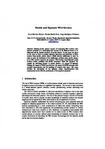
are described by activity diagrams. Such an activity diagram will describe the interactions between client and server as well as possible user interactions on the client side. Fig. 4 shows the activity diagram detailing the “Place Reservation” use case from the use case diagram above.
Fig. 4: Place Reservation activity diagram
The activity diagram detailing a use case has three areas. Swimlanes separate client and server from the communication. Only object flows and control flows are valid model elements for the communication area. In the client and server areas, we use stereotyped actions according to the conceptual model (see Fig. 2). «LogicInterface»is the only valid action stereotype for the client side, as «Processor» and «Renderer» are for the server side. Thus, dynamic modules will be modeled as subactivity graphs containing invocations of the associated renderers and processors as action states. Choice nodes may be used to evaluate the return value from a processor and make a decision between different execution flows. These execution flows may end in different renderers. The business logic will be contained in action states, which have to be detailed to provide the actual implementation of a certain action. To extract the server side subgraph related to a dynamic module, the graph has to be traced from an incoming control- or object flow to all reachable renderers. The client side subgraph can be found by tracing from all the renderers in the server side subgraph to the links. These two subgraphs are the basis for the code generation from the activity diagram, as they contain the description of both the behavior and the structure of a dynamic page. The necessary data information can be extracted from the type definition of the instances in the object flow. A data structure class diagram will be used for the description of the data processed by the Web application. This diagram shows the structure and composition of both transient and persistent data. All data passed in the activity diagrams using object flows has to be typed consistently with this class diagram. Fig. 5 shows the part of the class diagram for our reservation example, which is relevant to our example use case “Place Reservation”.
Fig. 5: Part of the Reservation System data structure class diagram
It is important to distinguish between display data and editable data in the object flows. This information is essential for later code generation. Therefore, the objects in these object flows are assumed to be in a composite state according to the state chart diagram shown in Fig. 6. The state also reflects the persistence of the object. Persistent objects allow the generation of pure references in cases when data is only intended for parameter passing to the next activity.
Fig. 6: Data Flow Object State
To add business logic details to an activity diagram, the «Processor» actions can be detailed using a subactivity diagram. This diagram may contain action states as well as object flows that are typed consistently with the class diagram. Actions in this diagram may be detailed by a diagram of the same kind. The return values of the action states can be checked in guards. For the subactivity diagram related to those action states, the name of last action state visited will be considered as the return value to the parent activity diagram. contains
Serv erPage 1..n
Serv erPageModule 1..n
contains
Link
DesignModule
LogicModule
1..n Alternativ e
BeginUseCase
1..n
UseCase
1
LogicElement uses 1..n
1..n
1..n
UserDecision
allows
Fig. 7: Metamodel for site structure diagrams
next
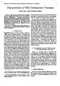
To compose the server page modules to server pages we have to relate certain elements from our conceptual model. Fig. 7 shows a metamodel containing the relevant elements from the conceptual model shown in Fig. 2. Instances of this metamodel are employed as a site map tailored to the specific needs described above. The model supports the reuse of server page modules and the integration of the behavioral description via associations to use cases, logic modules and their logic elements. Fig. 8 shows an example for a simple site structure diagram of our reservation system example. The semantics of a link between a design module and a server page depends on the subtype of link (see Fig. 7) used. While the basic link type indicates a simple link to another server page, the «BeginUseCase» link indicates that the associated use case will be executed by the target server pages. This implies that the target server page must have an association to the corresponding logic module. In our example, the use case PlaceReservation is part of the logic module ReservationSystem. Thus, the target server page for the «BeginUseCase» link associated to PlaceReservation must contain the corresponding ReservationSystem logic module. Since the corresponding logic module is determined by the composition between the use case and that logic module there is no need to explicitly associate the target logic module to the link. The same principle applies to «Alternative» links. These links indicate a change in the surrounding page within a use case. This implies that the corresponding logic module must be the link source logic and the target server page must be associated to the same logic module to provide a valid structural environment for the use case. «BeginUseCase» +
UseCase: = PlaceReservation
«DesignModule» Nav igationBar
«ServerPage» Reserv ation
«LogicModule» Reserv ationSystem
«Link»
«Link» «DesignModule» Greetings
«ServerPage» WelcomePage
«DesignModule» CommonElements
«DesignModule» Header
Fig. 8: Site structure diagram for the reservation system example
Jointly the presented models form a complete structural and behavioral description of those parts of the Web application, which are needed for the communication within the development team and with the customer. Furthermore, the model can be used for code generation leading to rapid prototyping from the model.
4
Code Generation from Models
In the following, we explain how the models in our approach can be used for the generation of a running prototype using PHP as the scripting language. We will
describe our approach on a per-diagram basis. This will yield the necessary server side modules to create a complete running prototype. 4.1 Use Case Diagrams We mainly apply the use case diagrams to generate HTML modules for the designer of the Web pages. A HTML module, consisting at first on of a set of links, will be generated for each actor in the use case diagram. Each of these links is generated from a use case the actor is connected with. The link either references a page including a HTML module for starting a workflow modeled by an activity diagram or a HTML page including another static HTML module derived from a use case diagram detailing a top-level use case of the corresponding link. As a result, a tree of modules generated from more and more refined use cases is obtained. The developer can use these HTML modules to test the whole Web application. Therefore, the HTML modules have to be embedded in complete Web pages, as explained later in section 4.3. For example, from the use case diagram in Fig. 3 two HTML modules are obtained. The HTML module generated for the clerk (see below) consists of three links. All three links are referencing a server page, which includes modules to accomplish the corresponding use cases. The names to reference the server pages are taken from the site structure diagram, where the embedding of the modules in server pages is modeled. To show the correct module in the server page, it has to be referenced with parameters specifying the logic module and the use case to perform. The following HTML extract is an example for a module, which is possible integrated in a page, where the clerk can start all for him possible use cases.
Starting module of Reservation System (clerk)
Cancel Reservation