Jun 1, 1996 - source coding scheme and the use of binary rate-compatible punctured ... channel coding can be treated separately and if the rate-distortion ...
June, 1996
LIDS-P 2344
Research Supported By: German Educational Exchange Service (DAAD) ARPA contract F30602-92-C-0030
Rate-Distortion Performance for Joint Source and Channel Coding of Images
Ruf, Michael J. Modestino, James W.
~June 1996
LIDS-P-2344
Rate-Distortion Performance for Joint Source and Channel Coding of Images* Michael J. Ruf
James W. Modestino
German Aerospace Research Establishment (DLR)
ECSE Department
Institute for Communications Technology
Rensselaer Polytechnic Institute
D - 82234 Wessling, Germany
Troy, NY, 12180, U.S.A.
Abstract This paper describes a methodology for evaluating the rate-distortion behavior of combined source and channel coding schemes with particular application to images. In particular, we demonstrate use of the operational rate-distortion function to obtain the optimum tradeoff between source coding accuracy and channel error protection under the constraint of a fixed transmission bandwidth. Furthermore, we develop information-theoretic bounds on performance and demonstrate that our combined source-channel coding methodology results in rate-distortion performance which closely approach these theoretical limits. We concentrate specifically on a wavelet-based subband source coding scheme and the use of binary rate-compatible punctured convolutional (RCPC) codes for transmission over the additive white Gaussian noise (AWGN) channel. Explicit results for realworld images demonstrate the efficacy of this approach.
1
Introduction
Shannon's information theory has established that, in the limit of large block sizes, source and channel coding can be treated separately and if the rate-distortion function of the encoded source is smaller than the channel capacity,'theoretically achievable performance is limited solely by source coding errors. However, it can be observed in real-world systems that, even if the source encoded bit stream is almost statistically independent, the individual bits normally differ in their relative importance or sensitivity, and thus should be protected against channel errors according to their *This work was performed at the ECSE Dept., Rensselaer Polytechnic Institute, Troy, NY 12180 and was supported by the German Educational Exchange Service (DAAD) as part of the HSP II-program, and in part by ARPA under Contract No. F30602-92-C-0030.; and DAAH04-95-1-0103 (Laboratory for Information and Decision Systems, Massachusetts Institute of Technology).
respective effects on the reconstructed image. In recognization of this fact a number of approaches have been developed for improving the quality of reconstructed images under noisy channel conditions while maintaining a fixed overall transmission bandwidth.
These techniques include: a
number of source and channel coding strategies with specifically tailored assignment of channel codes to different encoded bit positions [1, 2, 3]; various schemes that combine blocked source data structures and channel coding to limit propagation of channel error effects for variable-length and/or predictive coded data [4, 5]; and source-controlled channel decoding schemes [6] that use residual correlation in the encoded data to improve bit-error performance and hence reconstructed image quality. All of these techniques have been shown to provide some degree of performance improvement in the presence of channel errors. In this paper, we describe how the quantization errors and the channel error effects contribute to the overall distortion as an explicit function of the number of quantization bits used for the different source data streams and on the specific channel codes employed for operation over an additive white Gaussian noise (AWGN) channel at a specific value of Es/No. This will enable us to develop an approach for jointly distributing source and channel bits in an optimum way. In distinction to the work in [3], where a two-stage bit-allocation, first for source and then for channel bits under the constraint of a common overall rate, was used to find the minimum overall distortion over all possible source rates, we describe an improved process with a single joint bit-allocation. This approach considers both the effects of quantization and channel errors contributing to the distortion in case of a noisy environment and allows a trade-off between quantization noise and channel errors in an optimum way. Furthermore, in order to provide a context for this work, we extend this approach to obtain a series of information-theoretic bounds on the achievable performance of practical combined source-channel coding approaches. This allows direct evaluation of the relative efficacy of different quantization, coding and error protection schemes and, in particular, demonstrates that the approach described here provides performance closely approaching these theoretical limits. This paper is organized as follows. In Section II, we first give a brief description of the source coder, the statistical properties of the various data streams and the different quantizers used. The derivation of the individual sensitivities of the coded bits, depending on the quantizers and the number of quantization bits, is developed together with a comparison of simulated results in Section III. In Section IV, we briefly discuss the channel coder and we describe an approach for optimizing the rate-distortion performance for the (real-world) transmission systems employed, along with
2
some simulation results. In Section V, we extend the rate-distortion approach to the development of general information-theoretic bounds and compare different image transmission schemes. Finally, in Section VI we provide a summary and conclusions.
2
Source Coder Discrete Wavelet Transform
2.1
As in other source coding schemes, the image first undergoes a transformation before quantization to decorrelate the source signal and to make the data more suitable for compression. This could be done by a discrete cosine transform (DCT) [7] or a subband transform (SBT) [8]. Since multiresolution representations, or discrete wavelet transforms ('WVT), have been applied very successfully in image coding [9] and have demonstrated superior performance, both subjectively and objectively and for both low and high degrees of compression, we will combine this technique with two different scalar quantization schemes to build a base for optimizing the rate-distortion behavior of the joint source and channel coders. The basic idea of the discrete wavelet transform is the approximation of a full resolution (r=O) 1f
/D2 Dlf, by its discrete detail representations D°lf, image, denoted A of, 0
together with the
subimage at resolution r = 1, denoted A-_f. A subsequent approximation of A-if by A- 2 f and
&
2 f,
Dl 2 f D _ 2 2 f can be applied iteratively obtaining the mapping at resolution r Aof -
(A-rf, DO rf, Drf,
r+f,...
D -rf, Dlir+f,D+lf
f,
f,
f)
(1)
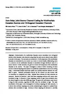
Here D°rf,X Dlrf and D2_rf are the detail representations of A-_+lf at resolution r and A_rf is the resulting resolution r subimage. This discrete wavelet decomposition is illustrated in Fig. 1. -0
D 2 f=
-r f=T1
I
D_% f.=
DTk5 f = Tk-2
_22 f=
Tk-4
Tk-3
,, f= Tk-.I
f= Tk
Figure 1: An illustration of the wavelet transformed image. For images, the discrete representations D°rf, Dl, f,r2
3
rf and the subimage Arf
at res-
olution r can be computed from the subimage A-r+lf at resolution (r - 1) by filtering first the rows and then the columns of A-r+lf followed by subsampling by a factor of 2. The discrete representation of the original image at resolution r then consists of K := 3r + 1 subimages. The two filters (gm)mEz and (hm)mEZ which are used to effect the iterative resolution into low and high spatial frequency components, respectively, are related by the condition g, = (-l)l-m
hl-m.
Furthermore, wavelet theory shows that IH(w)12 - IH(w + r)l12 = 2 for perfect reconstruction, so the filters have the characteristics of quadrature mirror filters (QMFs). Finally, the inverse wavelet
transform can be performed by upsampling Dorf, DLrf, D2_rf and A_rf by a factor of 2 and subsequent filtering. In the work reported here, the Johnston 16-tap (b) filter [10] was used for the elementary row and column filtering steps. In the following, let us denote the subimages of the wavelet transformed image matrix T as T1 = A-_f, T 2 = D°rf, T 3 = l rf, T 4 = D2f, T 5 = Dfr+lf, etc.
2.2
Statistical Properties of the Source Coders
It has been shown [4] that the histograms of the various subimages can be modeled reasonably accurately in terms of the generalized Gaussian (GG) distribution p(X) = 2(1)
exp
/ai
(2)
with a a scale parameter and the parameter /3 controlling the exponential rate of decay.
The
parameters a, / associated with a particular subimage can be calculated from the corresponding samples x = (xo, x 1 , ..., xs-1 ) of that subimage, their expectation /, their first two absolute moments
A1 = E(Ix -
l2) as c = A1 Ir(
l) and A2 = E(lx-
r(3//3) _ F(1//3)
2
3 = F-'(A2)
A2
;with
), using .
F(P)= r(1//) r(3/) r2(2//3)
(3)
Results have shown that all AC'-subimages match the GG-model very good, while the DC-subimage does not and thus will be modeled by a Gaussian distribution (i.e., a =
and /3 = 2, with a 2
the variance of the samples x). 'We use a loose notation here, denoting the lowest-frequency band as the DC-subband and all the higher-frequency bands as AC-subbands
4
2.3
Quantization and Coding
2.3.1
Scheme A: Uniform Threshold (UT) Quantizer
In this very basic and very fast quantization scheme, the range Q of the samples 2 of the subimage is divided into N = 2n equally spaced intervals with
Xt,k
(O < k < N) the quantization thresholds
and n the number of quantization bits per sample. The reconstruction levels will be computed as Xl,k = (xt,k -
xt,k+l)l2. The mean-square error (mse) due to quantization can then be roughly
estimated as eUT" = 1(4)) 2.3.2
Scheme B: Optimum (nonuniform) Generalized Gaussian (GG) Quantizer
In the second scheme, the fact that the histograms of the AC-subimages can be modeled as generalized Gaussian (GG) distributions is used. We follow a procedure described by Roe [11] and applied it to the generalized Gaussian distribution (see Appendix A), to calculate the optimum quantization intervals with nonuniform spacing. Because of symmetry about the origin, the reconstruction levels Xl,k for a mean-square error criterion (9 = 2) or a linear distortion measure (9 = 1) can easily be derived as sk, =
a[(1
+
- P-
p2k +
1)
for
- N )]
N/2 < k
N
,
(5)
with P-l(a, x) the inverse function of the incomplete Gamma-function P(a, x). The reconstruction levels for 0 < k < N/2 follow as
XZ,k
= xl,(N-l-k) and the correction term Ks for 0 = 2 can be
evaluated as (see Appendix A) i~2
[~i r(2~r(l/$) (.3 )*(6)
The quantization thresholds xt,k can similarly be derived as a [(1 Xtk= =[(1+ (I +
) I )0
itk (-
N N+ -
J
)]1/3
;for j1s
N/2....
s
i4 30
35 ni----
4.0
Figure 4: Overall rate-distortion behavior of joint source and channel coding, applied to subband i=3, no code-allocation, UT-quantizer.
4.2.2
Code-Allocation within a Subband
To improve the overall performance, one can perform a code-allocation (CA) within every subband. This means, that the ni different source bits of subband i can receive different protection (according to their needs). This seems logical, since the source bits cover a wide range of sensitivities (see Fig. 2), and it obviously is a waste of resource (redundancy) if we do not make use of some form of unequal error protection (UEP). The calculation of the operational R-D-functions of the different subbands is then altered in the following way. After assigning a specific number of quantization bits ni one has to perform code-allocation procedures before incrementing ni. The code-allocation is done for average channel rates ranging from Rmin = 1.0, which means every source bit has no channel coding, to Rmax = Rf=F, which means every source bit obtains maximum protection. An average channel code rate A with Rmin < R < Rmax means the available redundancy is 4Note that in this case (i = 3), all possible distortions for ni = I are greater than the variance (ni = 0) and thus are not considered when evaluating the operational joint rate-distortion function.
16 16
allocated in an optimum way to the different sensitivities (different code rates to the different sensitive bits, UEP) as to minimize the channel distortion Dc,i(ni). WVe plotted this procedure for the same conditions as above in Fig. 5a, where one can see, as a result of the performed codeallocation, the much smoother and steeper behavior of the corresponding R-D-function (compared to Fig. 4), which means increased performance and more variety for the later joint source-channel bit-allocation to choose from. To show the benefits of this code-allocation procedure and the better source coding performance of the GG-quantizer, we plotted the final R-D-functions (the same conditions apply as before) for the UT- and GG-quantizer in Fig. 5b. As one can see, the performance improves when using CA for the UT instead of none. Furthermore, using the GG-quantizer increases the performance even more. Furthermore, to dramatically enhance the performance of the source coder, similarly to [15], we partitioned every subband into fields with size equal to that of the low-frequency subband (i = 1). Since different fields of one subband represent different regions of the image, depending on the image content they may have very different statistical properties. This gives the joint bit-allocation a much wider variety of choices for allocating bits (i.e., local adaptivity). So, for the remainder, we consider K=16 subbands after the wavelet transform, partitioned into Ik=1024 fields, and for the source-channel coding, we use the GG-quantizer with CA. 4.3
Simulation Results
Having the operational R.-D-functions, the joint bit-allocation based on [13] assigns bits to the bands, in order to obtain the minimum overall distortion for a given overall rate Rs+c for a specific channel signal-to-noise ratio. Contrary to [3], where we used a two-stage algorithm for the bit-allocation, to allocate the channel bits after the source bits, and then searched for the optimum source-to-channel rate ratio, here we jointly allocate source and channel bits in a single bit-allocation. The analytical overall performance is shown in Fig. 6a, where we plotted the R-Ddiagrams of the 1024 field-GG scheme for different Es/No on an AWGN channel. One can see the typical R-D-behavior including the improved performance (lower distortion) with increasing signalto-noise ratio. We also included some simulation results with the LENNA image, being actually source and channel encoded, transmitted and decoded (with some remaining channel errors) 50 times. This was done for the overall rates Rs+c=0.5, 0.75 and 1.0 bpp and an E 8 /No=O, 2 and 4 dB, using the v = 6 RCPC codes. The exact values of simulation and analysis can be found in Table 2. The side information to be transmitted, which comprises the statistical properties of the
17
Joint LENNA, 2.5 rnii0
ourC¢-Channel
Es/No=O dB,
i
late-Distortionr
BER=0.0786,
UT-quantizer, -.A-D (s-+c) fcr
hi=-2
finia
ni=0,
n,=0-1 1, with
R-D Es-.c
.. ,1 1
with
bits,
i=3
CA
CA
-0.5
-1 .5
-0.5
i ' dO diffaranc, with code-------allocationT-quanti=5 0 dB,ni=3 B 07861----------------n1
-i i. 4; 4;/N-t,--,
L
1.5
-4 .5
bitsi=
of
...........................................
0
5
~~~~~~~~~~~~-0.5 ~ri= 1 0
15
20
RF._,c
[cCu-
25 per
pixel] final R-D
30
35
40
-- > (S-----C),no--LUT,
45
CA
a.) with code-allocation,for UT-quantizer 1 -30.5 .5
i=3.
Figure rate-distortiNN 5: Overall /=O
, E
firimi Fl.............-D (S+.C)
T, , with CA.
=007,source and channel cod1 itng,i=
finalss bit-erro ofquantization C),and , Crates. 1 n5 Fig. b, we compare the joint R-D-behavior of three different schemes CA), (with fi0al
the 16 band-UT,
1024 the field-UT
th
5R-E
C--)
-,
with
1024 andfield-GG e scheme for an Eg/N0 =0 dB. O 18 18
namely
CA|
ne can
E s /No
Rs+c
(BER uncod.) 0 dB
[c.u./ pixel] 0.5 0.75 1.0 0.5 0.75 1.0 0.5 0.75 1.0
Ds [mse]
Dc [mse]
Ds+c [mse]
Ds+c [PSNR]
analyt. } simul.
analyt. ] simul.
analyt. I simul.
[dB]
(7.9.10-2) 2 dB (3.8.10-2) 4 dB (1.3.10- 2)
analyt. 42.42 27.56 19.81 32.93 20.85 14.89 26.41 16.31 11.57
[ simul. 43.15 28.27 20.30 33.42 21.28 15.29 26.98 16.60 11.83
4.26 3.06 2.46 3.31 2.25 1.56 1.86 1.37 0.94
4.67 3.09 2.40 3.41 2.24 1.49 2.89 2.05 1.33
46.68 30.62 22.26 36.24 23.11 16.45 28.28 17.68 12.51
47.82 31.37 22.70 36.83 23.53 16.78 29.87 18.65 13.16
31.44 33.27 34.66 32.54 34.49 35.97 33.62 35.66 37.16
Table 2: Performance of joint source channel coding for code memory see the improvement as one moves to more and more sophisticated schemes.
i,
31.34 33.17 34.57 32.47 34.42 35.88 33.38 35.43 36.94
= 6.
Note that these
overall operational R-D-functions can be calculated, for every source-channel coding scheme, once a specific channel code family is chosen (with the knowledge of the associated BER-performance) and provided that there exists an analysis of source coding error and of the sensitivity to channel errors. We also illustrated in Fig. 7 some representative images, which were transmitted over an AWGN-channel at a signal-to-noise ratio of Es/No=O dB and an overall rate of Rs+c=l.0 bpp. One can get a very good indication of the improvements if one compares the images, beginning from an unprotected image with no transmission error (a), to an unprotected image with channel errors (b), on to the various schemes with increasing performance (16-UT (c), 1024-UT (d) and 1024-GG (e)) and, finally, comparing them to the result of a transmitted image at the channel capacity (f). The same results for EslNo=2 dB and R,+,=0.5 bpp can be seen in Fig. 8. Both figures show the large amount of distortion due to channel errors in the unprotected images (b). The jointly optimized images of the 16-UT (c) scheme look much better, but still the images indicate the effects of the quantization error due to the-suboptimum source coding performance. With better source coding (1024-UT (d)), we increase the quality of the image, but there is some distortion noticeable. The best results can be obtained with the 1024-GG scheme (e), which combines sharpness with less annoying noise. The best theoretical quality, assuming the 1024-GG scheme, but no channel errors when transmitting at the channel capacity (f), shows only minor improvements in the case of Es/No=2 dB and Rs+¢=0.5 bpp (Fig. 8) and almost no improvement in the case of Es/No=O dB and Rs+c=1.0 bpp (Fig. 7). The coding results (PSNR and Rs) of the images can be seen in 19
1 024 WV'T · 1 .50
field-GG, .
..
LENIJA '"
2,
512-51
=
,
AWVVC
,
4-
0,
-2, _
r-nalysis simulation
0
20
300
4
2
irg
C
anel
C. ..