Non-Orthogonal Multiple Access (NOMA). Multiplex users in power (and spatial) domain using (linearly precoded). Superposition Coding with SIC (SC-SIC).
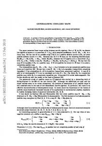
Rate-Splitting Multiple Access: Bridging, Generalizing and Outperforming SDMA and NOMA Yijie Mao∗ , Bruno Clerckx† and Victor O.K. Li∗ ∗
The University of Hong Kong, Hong Kong, China † Imperial College London, United Kingdom
Imperial College London, February 2018 EPSRC funded project EP/N015312/1
1 / 24
Space-Division Multiple Access (SDMA) Multiplex users in spatial domain using Multi-User Linear Precoding (MULP) • MU-MIMO, CoMP, network MIMO, mmw MIMO and Massive MIMO Pros: 1
Reap all spatial multiplexing (DoF) benefits of a MISO BC with perfect CSIT
2
Low precoder and receiver complexity
Cons: 1
Suited to underloaded regime, not overloaded regime
2
Suited to semi-orthogonal users with similar channel strengths, not general settings
3
DoF optimal with perfect CSIT, not with imperfect CSIT
2 / 24
Non-Orthogonal Multiple Access (NOMA) Multiplex users in power (and spatial) domain using (linearly precoded) Superposition Coding with SIC (SC-SIC) Pros: 1
Cope with an overloaded regime with diversity of user channel strengths
Cons: 1
SC-SIC motivated by a SISO BC. DoF loss in MISO BC.
2
Suited to aligned users with diverse channel strengths, not general settings
3
Complexity at both the transmitter (opt. of precoders, groups and decoding orders) and the receivers (multi-layer SIC)
4
DoF loss in imperfect CSIT
3 / 24
SDMA and NOMA: The Extremes Two extreme interference management strategies: fully treat interference as noise and fully decode interference SDMA: fully treat any residual multi-user interference as noise NOMA: some users fully decode and cancel interference created by other users Analogy with the two-user Gaussian SISO IC
4 / 24
Rate-Splitting Multiple Access (RSMA) Multiplex users in spatial and power domains using linearly precoded Rate-Splitting (RS) with SIC Decode part of the interference and treat the remaining part as noise • Bridge the extremes • General and powerful multiple access framework Pros: 1
Encompass SDMA and NOMA as special cases
2
RSMA rate ≥ SDMA and NOMA rates
3
Optimal from a DoF perspective in both perfect and imperfect CSIT
4
Cope with any user deployments (diversity of channel strengths and directions), CSIT inaccuracy and network load
5
Lower computational complexity than NOMA for both the transmit scheduler and the receivers
Cons: 1
Higher encoding complexity than SDMA and NOMA 5 / 24
RSMA: Two-User Example Transmitter • W1 , W2 split into {W112 , W11 } for user-1 and {W212 , W22 } for user-2 • W112 , W212 are encoded together into a common stream s12 • W11 and W22 encoded into private stream s1 for user-1 and s2 for user-2 • Data streams are linear precoded x = p12 s12 + p1 s1 + p2 s2 Receiver • Both users first decode s12 by treating s1 and s2 as noise • Both users perform SIC and retrieve s1 and s2 , respectively SIC (or joint decoding) needed to separate common and private streams
6 / 24
SDMA and NOMA: subsets of RSMA
SDMA based on MU-LP • Simply allocate no power to s12 and treat multi-user interference as noise x = p1 s 1 + p2 s 2 NOMA based on SC-SIC • Forcing user-1 to fully decode the message of user-2 • Allocate no power to s2 , encode W1 into s1 and encode W2 into s12 x = p12 s12 + p1 s1 • User-1 and user-2 decode s12 by treating s1 as noise and user-1 decodes s1 after canceling s12 • NOMA more restrictive with p12 = p1 7 / 24
RSMA: Three-User Example General RS framework for 3-user
SDMA and NOMA again subsets of RSMA Framework extendable to K-user 8 / 24
Low-Complexity RSMA Adjust the number of SIC layers and common messages 1-layer RS (K = {1, . . . , K}) x = Ps = pK sK +
X
pk s k
k∈K
• Only one SIC required at each receiver • No user ordering/grouping at the transmitter • MU-LP subset of 1-layer RS • SC-SIC not a subset of 1-layer RS (for K > 2)
9 / 24
Low-Complexity RSMA 2-layer Hierarchical RS (HRS) x = Ps = pK sK +
X
g∈G
• • • •
pK g s K g +
X
pk s k
k∈K
Two layers of SIC required at each receiver User grouping but no user ordering at the transmitter MU-LP subset of 1-layer HRS SC-SIC not necessarily subset of 1-layer RS
10 / 24
Optimization
RRS3 (u, π) = arg max P,c
s.t.
C1123 +
3 X
uk Rk,tot
k=1 123 C2 + C3123
≤ R123
C112 + C212 ≤ R12 C113 + C313 ≤ R13 C223 + C323 ≤ R23 tr(PPH ) ≤ Pt Rk,tot ≥ Rkth , k ∈ {1, 2, 3} c≥0
11 / 24
SDMA vs NOMA vs RSMA
12 / 24
Complexity SDMA vs NOMA vs RSMA
13 / 24
Numerical Results Compare SDMA, NOMA and RSMA Effect of user channel alignment/orthogonality θ and channel strength disparity γ h1 = [1, 1, 1, 1]H , h iH h2 = γ × 1, ejθ , ej2θ , ej3θ
Effect of load: underloaded (K ≤ Nt ) and overloaded (K > Nt ) regime Effect of CSIT inaccuracy
14 / 24
Numerical Results: K = 2, Nt = 4, Perfect CSIT (a) θ=π/9, γ=1
10
8
R2 (bit/s/Hz)
8
R2 (bit/s/Hz)
(b) θ=2π/9, γ=1
10
6 4 2
6 4 2
0
0 0
2
4
6
8
10
0
2
R1 (bit/s/Hz) (c) θ=π/3, γ=1
10
6
8
10
8
10
(d) θ=4π/9, γ=1
10 8
R2 (bit/s/Hz)
8
R2 (bit/s/Hz)
4
R1 (bit/s/Hz)
6 4
DPC RS SC-SIC MU-LP
2
6 4 2
0
0 0
2
4
6
R1 (bit/s/Hz)
8
10
0
2
4
6
R1 (bit/s/Hz)
Figure: Achievable rate region of different strategies when γ = 1, SNR=20 dB. 15 / 24
Numerical Results: K = 2, Nt = 4, Perfect CSIT (a) θ=π/9, γ=0.3
6
5
R2 (bit/s/Hz)
5
R2 (bit/s/Hz)
(b) θ=2π/9, γ=0.3
6
4 3 2 1
4 3 2 1
0
0 0
2
4
6
8
10
0
2
R1 (bit/s/Hz) (c) θ=π/3, γ=0.3
6
6
8
10
8
10
(d) θ=4π/9, γ=0.3
6 5
R2 (bit/s/Hz)
5
R2 (bit/s/Hz)
4
R1 (bit/s/Hz)
4 3 DPC RS SC-SIC MU-LP
2 1
4 3 2 1
0
0 0
2
4
6
R1 (bit/s/Hz)
8
10
0
2
4
6
R1 (bit/s/Hz)
Figure: Achievable rate region with different strategies when γ = 0.3, Nt = 4, SNR=20 dB.
16 / 24
Numerical Results: K = 2, Nt = 4, Imperfect CSIT (a) θ=π/9, γ=1
10
8
R2 (bit/s/Hz)
8
R2 (bit/s/Hz)
(b) θ=2π/9, γ=1
10
6 4 2
6 4 2
0
0 0
5
10
0
R1 (bit/s/Hz) (c) θ=π/3, γ=1
10
10
(d) θ=4π/9, γ=1
10 8
R2 (bit/s/Hz)
8
R2 (bit/s/Hz)
5
R1 (bit/s/Hz)
6 4 RS SC--SIC MU--LP
2
6 4 2
0
0 0
5
R1 (bit/s/Hz)
10
0
5
10
R1 (bit/s/Hz)
Figure: Achievable rate region of different strategies when γ = 1, Nt = 4, SNR=20 dB. 17 / 24
Numerical Results: K = 2, Nt = 4, Imperfect CSIT (a) θ =π /9, γ=0.3
(b) θ =2 π /9, γ=0.3
6
R2 (bit/s/Hz)
R2 (bit/s/Hz)
6
4
2
0
4
2
0 0
5
10
0
R1 (bit/s/Hz) (c) θ =π /3, γ=0.3
4
RS SC--SIC MU--LP
2
10
(d) θ =4 π /9, γ=0.3
6
R2 (bit/s/Hz)
R2 (bit/s/Hz)
6
5
R1 (bit/s/Hz)
0
4
2
0 0
5
R1 (bit/s/Hz)
10
0
5
10
R1 (bit/s/Hz)
Figure: Achievable rate region with different strategies when γ = 0.3, Nt = 4, SNR=20 dB. 18 / 24
Numerical Results: K = 3, Nt = 2, Perfect CSIT (a) θ 1 =π/9, θ 2 =2π/9
(b) θ 1 =2π/9, θ 2 =4π/9
6
Weighted Sum Rate (bit/s/Hz)
Weighted Sum Rate (bit/s/Hz)
6 5 4 3 2 1 0
5 4 3 2 1 0
0
10
20
30
0
10
SNR (dB) (c) θ 1 =π/3, θ 2 =2π/3
6 5
30
(d) θ 1 =4π/9, θ 2 =8π/9
7
RS SC-SIC MU-LP 1-layer RS SC-SIC per group
Weighted Sum Rate (bit/s/Hz)
Weighted Sum Rate (bit/s/Hz)
7
20
SNR (dB)
4 3 2 1 0
6 5 4 3 2 1 0
0
10
20
SNR (dB)
30
0
10
20
30
SNR (dB)
Figure: Weighted sum rate versus SNR comparison of different strategies for overloaded three-user deployment with perfect CSIT, γ1 = 1, γ2 = 0.3, u1 = 0.4, u2 = 0.3, u3 = 0.3, Nt = 2, rth = [0.02, 0.08, 0.19, 0.3, 0.4, 0.4, 0.4]
19 / 24
Numerical Results: K = 3, Nt = 1, Perfect CSIT σ21 =1, σ22 =0.3, σ23 =0.1
6
SC-SIC, u =0.2, u =0.3, u =0.5 1
2
3
1-layer RS, u =0.2, u =0.3, u =0.5 1
Weighted Sum Rate (bit/s/Hz)
5
2
3
SC-SIC, u 1 =0.4, u 2 =0.3, u 3 =0.3 1-layer RS, u 1 =0.4, u 2 =0.3, u 3 =0.3 SC-SIC, u 1 =0.6, u 2 =0.3, u 3 =0.1
4
1-layer RS, u 1 =0.6, u 2 =0.3, u 3 =0.1
3
2
1
0 0
5
10
15
20
25
30
SNR (dB)
Figure: Weighted sum rate versus SNR comparison of different strategies for overloaded three-user deployment with perfect CSIT, σ12 = 1, σ22 = 0.3, σ32 = 0.1, Nt = 1, rth = [0, 0, 0.01, 0.03, 0.1, 0.2, 0.3]
20 / 24
Numerical Results: K = 4, Nt = 2, Perfect CSIT (a) θ 1 =0
(b) θ 1 =π/18
4
Weighted Sum Rate (bit/s/Hz)
Weighted Sum Rate (bit/s/Hz)
3.5 3 2.5 2 1.5 1 0.5 0
3
2
1
0 0
10
20
30
0
10
SNR (dB) (c) θ 1 =π/9
3
30
(d) θ 1 =π/6
4
2-layer HRS SC-SIC per group MU-LP 1-layer RS per group 1-layer RS
Weighted Sum Rate (bit/s/Hz)
Weighted Sum Rate (bit/s/Hz)
4
20
SNR (dB)
2
1
0
3
2
1
0 0
10
20
SNR (dB)
30
0
10
20
30
SNR (dB)
Figure: Sum rate versus SNR comparison of different strategies for overloaded four-user deployment with perfect CSIT, γ1 = 0.3, θ2 = θ1 + π9 21 / 24
Numerical Results: K = 10, Nt = 2, Perfect CSIT
Weighted Sum Rate (bit/s/Hz)
20 1-layer RS SC-SIC MU-LP multicast
15
10
5
0 0
5
10
15
20
25
30
SNR (dB)
Figure: Weighted sum rate versus SNR comparison of different strategies for 2 = 1, N = 2, overloaded ten-user deployment with perfect CSIT, σ12 = σ22 = . . . = σ10 t SNR=30 dB,rth = [0.01, 0.03, 0.05, 0.1, 0.1, 0.1, 0.1] 22 / 24
Numerical Results: K = 10, Nt = 2, Perfect CSIT
Individual Rate (bit/s/Hz)
10 2 1-layer RS SC-SIC MU-LP multicast
10 1
10 0
10 -1
10 -2
1
2
3
4
5
6
7
8
9
10
users
Figure: Individual rate comparison of different strategies for overloaded ten-user deployment with perfect CSIT for 1 randomly generated channel estimate, SNR=30 dB, Nt = 2, rth = [0.01, 0.03, 0.05, 0.1, 0.1, 0.1, 0.1]
DoF and rate gains with only 1 SIC layer vs NOMA that requires 9 SIC layers! Partially decode interference and partially treat interference as noise: enhanced throughput and QoS, increased robustness and lower complexity 23 / 24
Conclusions New multiple access called Rate-Splitting Multiple Access (RSMA) SDMA and NOMA subject to many limitations: high system complexity and a lack of robustness to user deployments, network load and CSIT inaccuracy General multiple access framework based on rate-splitting (RS) Partially decode interference and partially treat interference as noise 1-layer RS: low scheduler and receiver complexity and good performance in any user deployments, CSIT inaccuracy and network load RSMA has the potential to change the design of the PHY and MAC layers of next generation communication systems by unifying existing approaches and relying on a superposed transmission of common and private messages Reference Y. Mao, B. Clerckx and V.O.K. Li, “Rate-Splitting Multiple Access for Downlink Communication Systems: Bridging, Generalizing and Outperforming SDMA and NOMA,” arXiv:1710.11018. 24 / 24