Rationale for a 3D Heterogeneous Multi-core Processor Eric Rotenberg, Brandon H. Dwiel, Elliott Forbes, Zhenqian Zhang, Randy Widialaksono, Rangeen Basu Roy Chowdhury, Nyunyi Tshibangu, Steve Lipa, W. Rhett Davis, Paul D. Franzon Department of Electrical and Computer Engineering North Carolina State University Raleigh, North Carolina 27695
[email protected] Abstract— Single-ISA heterogeneous multi-core processors are comprised of multiple core types that are functionally equivalent but microarchitecturally diverse. This paradigm has gained a lot of attention as a way to optimize performance and energy. As the instruction-level behavior of the currently executing program varies, it is migrated to the most efficient core type for that behavior. This paper makes a case for implementing a heterogeneous multi-core processor via 3D die stacking. The case is framed from three angles: product strategy, architecture, and physical design. Product strategy: Die stacking enables plug-andplay composition of heterogeneous processors from homogeneous designs, a more efficient product customization strategy than fabricating dedicated 2D heterogeneous processors. Architecture: Frequent thread migrations substantially increase the benefits of microarchitectural diversity, but only if migration can be done with very low overhead. Thus, fast transfer of architectural state and uninterrupted access to accumulated microarchitectural state are essential. Physical design: Exchanging/referencing state between cores with low latency requires many new wires that must also be as short as possible, introducing intense physical design pressures and tradeoffs in a 2D layout that are diminished in a 3D layout. We are currently researching applications and fabricating prototypes of “H3”, a 3D heterogeneous multi-core processor. H3’s salient features include: two core types for optimizing latency and energy; a power management unit (PMU) that schedules migrations; fast thread migration (FTM) and cachecore decoupling (CCD) via face-to-face, microbump based buses; face-to-back, through-silicon-via (TSV) based buses connecting the core stacks to stacked L2 DRAM cache. The H3 project spans applications, processor architecture, circuits, logic and physical design/verification, design automation, fabrication and post-silicon validation. There are close interactions among all elements, both in terms of executing the project and in empirically justifying 3D-enabled heterogeneity. Thus, H3 is illustrative of the multi-disciplinary mission of this conference proceedings, the International Conference on Computer Design.
I.
I NTRODUCTION
A single-ISA heterogeneous multi-core processor (HMP) is comprised of multiple core types, that are functionally equivalent but microarchitecturally diverse. Core types may differ in their fetch and issue widths, pipeline depth, issue policy (in-order vs. out-of-order (OOO) issue), sizes of ILPextracting resources (reorder buffer/physical register file, issue
queue, load and store queues, etc.), predictors, caches, and frequency. Microarchitectural diversity provides new performance and power levers. Different programs or phases within a program differ in the amount and distribution of instructionlevel parallelism (ILP), and the frequency and distribution of performance-degrading events such as branch mispredictions and cache misses. In a HMP, as the instruction-level behavior of the currently executing program varies, the program is migrated to the core type best suited to the new behavior as judged by a figure of merit. Much of the HMP literature focuses on two or several core types with not-so-subtle contrasts in their peak performance and energy efficiency, for example, a big OOO core and a little in-order core, or some other fast/slow hybrid. The objective is to either minimize energy consumption of a single thread while minimizing latency impact [14], [20] or maximize throughput/watt/area of multiprogrammed, multithreaded workloads [4], [8], [13], [16], [26]–[29], [31]. For the single-thread case, the thread is migrated to the little core for phases that derive negligible performance benefit from the big core (phases with low ILP, frequent mispredictions, and/or frequent last-level cache misses). Thus, energy consumption is reduced, with only a mild slowdown compared to always running on the big core. For the multiple-thread case, the threads are analyzed and ranked from lowest to highest performancesensitivity across core types. Threads with highest sensitivity are given priority for the big core type and vice versa, achieving the highest throughput for the chip’s power and area budget. Other HMP proposals consider more core types with no fixed performance ranking among them: different program phases achieve their highest performance on different core types [7], [15], [23], [24]. In recent work, the objective is to accelerate a single thread by migrating it to the highestperforming core type for the current phase [25]. In this paper, we make a case for implementing HMPs using 3D die stacking. Section II frames the case from three angles: •
Product strategy – plug-and-play composition of many HMPs from a small portfolio of single-core-type chips.
•
Architecture – some applications of microarchitectural diversity are significantly enhanced when frequent migrations can be done with very low overhead. Physical design – 3D die stacking alleviates 2D physical design challenges when attempting to implement low-overhead migration mechanisms.
Section III provides an overview of our H3 project, which involves research, design and fabrication of a 3D HMP.
astar lbm perlbench
1 Little Core utilization
•
bzip2 libquantum povray
gcc mcf sjeng
go milc soplex
h264ref namd sphinx3
hmmer omnetpp xalancbmk
0.8 0.6
0.4 0.2 0 100
II.
R ATIONALE
A. Product Motivation: Plug-and-play Customization 3D integration is still a relatively immature technology. Challenges remain, such as how to independently test chips without fabricating the 3D stack (which would drive up cost), how to cool sandwiched die, and so forth. Nonetheless, it is incumbent on the community to anticipate what 3D integration enables assuming it matures as a technology. We believe there is excellent potential for designing families of plug-and-play chips, united through standard placements of through-silicon-via (TSV) and microbump based taps, that can be used to efficiently compose customized products for different applications and market segments.
B. Architecture Motivation: The Importance of Low-Overhead Thread Migration This section is divided into three subsections. In the first subsection, we show that the potential benefit of an HMP is greater with fine-grain thread migration than with coarsegrain thread migration. This assumes, however, that there is no migration overhead. In the second subsection, we discuss sources of migration overhead, and microarchitectural mechanisms to eliminate them. Finally, in the third subsection, we show that fine-grain thread migration is very sensitive to migration overhead, underscoring the importance of lowoverhead migration. These factors are evaluated for an HMP with two complementary core types: a big, high-performance OOO core and a little, low-power in-order core [10], [20]. A single thread is migrated between the two cores, with the goal of maximizing utilization of the little core (to extract the most energy savings) while achieving close to the performance of the big core (within a certain percentage) [14], [20].
migration interval
10K
100K
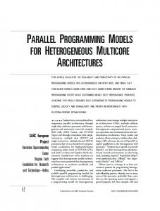
Fig. 1. Little core utilization vs. migration interval (for 5% performance degradation compared to always executing on big core).
1) Fine-Grain Thread Migration: We begin with an ideal experiment to get an upper bound on little-core utilization at different migration intervals. The migration interval is the minimum number of retired instructions for which the thread must remain on the current core, before migrating to the other core if it is deemed beneficial to do so. The experiment is ideal in two respects: •
Oracle migration schedule: The migration schedule – points at which the thread switches cores – is determined using oracle knowledge. The benchmark is executed on both cores, to determine the number of cycles to retire each interval on both cores. Thus, the slowdown of the little core relative to the big core is known a priori for all intervals. Then, all intervals are ranked from least slowdown to most slowdown, and intervals are scheduled on the little core in rankorder until the overall benchmark slowdown is 5%. The goal of this experiment is to understand the effect of switching granularity unclouded by artifacts of the core scheduling algorithm. Many researchers are exploring core scheduling for HMPs [4], [8], [13], [16], [20], [25]–[29], [31], [34].
•
Zero-overhead migration: Switching to the other core incurs no pipeline drain/refill penalty, no time to migrate execution, and no after-effects such as cold misses/mispredictions. We will explain these overheads in more detail in the next subsection.
In the case of HMPs, we advocate a product customization strategy whereby many different HMPs are composed from a smaller portfolio of homogeneous multi-core chips. For example, with five different plug-and-play core types, one can compose ten different two-core-type HMPs, ten different threecore-type HMPs, five different four-core-type HMPs, and one five-core-type HMP. Without 3D plug-and-play, achieving the same number of customized solutions requires 26 dedicated chip designs instead of just five. Moreover, 3D plug-and-play mitigates risk by decoupling core design teams and tapeout schedules. A late or canceled core type does not sink other products. In fact, staggering the core types may be beneficial in that it enables releasing new products more frequently.
1K
For each benchmark, we simulate the highest-weight 100 million instruction SimPoint [30] after a 10 million instruction warm-up period. Figure 1 shows little core utilization for different migration intervals while still achieving within 5% the performance of exclusively executing on the big core. In general, little core utilization increases as the migration interval decreases, due to the ability to exploit shorter intervals during which the little core performs close to the big core. But what is most interesting is that the trend is more prominent as the intervals get shorter. Utilization increases only modestly from the 100K to the 10K migration intervals, noticeably from 10K to 1K, and significantly from 1K to 100. 2) Sources of Migration Overhead and Mechanisms to Eliminate Them: There are three sources of migration overhead:
•
•
Transfer architectural register state: The thread’s architectural register state needs to be transferred from the source core to the destination core. Architectural register state includes all register state defined in the instruction-set architecture (ISA), including generalpurpose integer, floating-point, and SIMD registers, the program counter, etc. Conventionally, the transfer is done by two software handlers communicating through memory: one on the source core to store architectural register state to memory and another on the destination core to load architectural register state from memory. The two handlers synchronize using, for example, a software lock. The overheads are three-fold. First, there is the overhead of executing stores, loads and other instructions in the handlers. Second, both handlers’ memory operations inevitably miss in the respective private L1 caches because the memory blocks for saving/restoring registers pingpong between the cores. Third, using a software lock to synchronize the handlers is also inefficient. Migration-induced misses and mispredictions: Migration causes extra cache misses and branch mispredictions. An extra cache miss is incurred if, after migrating, the thread re-references a block that is in the previous cache but not in the current cache. In general, extra misses and mispredictions occur because there are training gaps while the thread is executing on the other core, another thread may evict blocks/counters while the thread is executing on the other core, and stores on the other core cause invalidations.
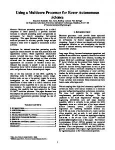
Figure 2 shows the results of an experiment in which the program is executed for 10 million instructions on a core and then migrated to another core with cold caches and predictors, where it executes for another 10 million instructions. The graph shows the number of extra cache misses, branch mispredictions, and cycles, compared to not migrating, i.e., executing all 20 million instructions on the first core. The two cores are identical and they each have private L1 and L2 caches and share the L3 cache. Although the L3 cache is shared, additional L3 misses can occur after migrating if the requested block is dirty in the first core’s cache and must first be flushed to the L3 cache before being returned to the second core. Benchmarks like perlbench, hmmer and libquantum incur relatively many extra cache misses, yet the increase in cycles is modest. On the other hand, mcf, omnetpp and xalancbmk incur relatively few extra cache misses, yet the increase in cycles is significant. The difference is in how well the benchmarks tolerate misses, i.e., the amount of ILP, amount of MLP, and the number of branch mispredictions that depend on cache misses.
I$ Misses
D$ Misses
L2 Misses
L3 Misses
Mispredictions
70 60 50 40 30 20 10 0
Fig. 2.
Cycles 1200 1000 800 600 400 200 0
cycles (thousands)
Drain and refill pipeline: Before the thread’s architectural register state can be transferred to the destination core, the source core needs to make a clean stop by flushing the pipeline or stopping instruction fetch and waiting for the pipeline to drain. Moreover, when the thread resumes on the destination core, there is a ramp-up penalty as the pipeline is refilled. Flushing or draining the pipeline and then refilling it, is tantamount to a branch misprediction. Thus, the overhead is similar to the penalty for a branch misprediction.
number of events (thousands)
•
Extra misses, mispredictions, and cycles due to the first migration.
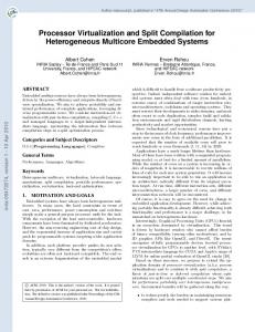
We are currently researching microarchitectural mechanisms to minimize migration overhead, including evaluating and comparing 2D and 3D physical designs of these mechanisms. Two of these mechanisms are Fast Thread Migration (FTM) and Cache-Core Decoupling (CCD). FTM addresses the second overhead, transferring architectural register state. As shown in Figure 3a, FTM is a massivelyparallel swap of all bits of the two cores’ Architectural Register Files (ARF). This all but eliminates the second overhead. Figure 3a depicts the classic OOO microarchitecture style, with its separate register files for committed state (ARF) and speculative state (Reorder Buffer (ROB)). The more contemporary OOO microarchitecture style holds both committed and speculative state in a unified Physical Register File (PRF). FTM is more challenging for this style because (1) the committed state is strewn throughout the PRF and (2) the PRFs are different in size, just as the ROBs are different in size. A parallel PRF-to-PRF copy works from the smaller to larger PRF but not the other way around (and also requires copying the mapping table). We are currently researching ways to implement FTM for the PRF style of microarchitecture.
I-Cache
I-Cache
IF
IF
MEM
MEM
D-Cache
D-Cache
ROB ROB
ARF
ARF
Massively Parallel ARF Swap
(a) Fast Thread Migration (FTM). Fig. 3.
(b) Cache-Core Decoupling (CCD).
Microarchitectural mechanisms for low migration overhead.
CCD addresses the third overhead, migration-induced misses. With CCD, when a thread migrates, it switches cores but not L1 caches. As shown in Figure 3b, each core can access the other core’s L1 instruction and data caches. Therefore, as a thread migrates between cores, it keeps using the same Icache and D-cache, thereby completely eliminating migrationinduced misses. Another key aspect of CCD is that it enables separately customizing the L1 caches and the pipeline to a program. This is a valuable specialization feature, since the best cache choice is closely linked to temporal and spatial locality, whereas
the best pipeline choice is closely linked to the amount and distribution of instruction-level parallelism. Moreover, CCD supports multiple modes of operation. Cores can be configured to use their own caches as usual. A thread can be mapped to the best core, L1 I-cache, and L1 D-cache for its entire execution. A thread can frequently hop between cores while using the same L1 caches throughout; or, in an occasional twist, it can start using different caches if they are better in the long-run after a major phase change. In a different vein, a thread may choose to stay on the same core for a long time, but frequently switch caches. For example, this is useful for splitting a thread’s working set across multiple L1 caches if it exceeds either L1 cache, using intelligent “migration” algorithms specifically designed for such working set splitting [21]. Depending on the microarchitecture implementation and physical design, accessing the other core’s caches may be slower and may have variable latency (e.g., asynchronous interfaces). We expect 3D stacking can help overcome physical design challenges facing planar designs of both FTM and CCD. An initial investigation of physical design aspects is presented in Section II-C. This research is on-going as part of the H3 project. 3) Sensitivity of Fine-grain Thread Migration to Migration Overhead: Previously, we demonstrated the value of finegrain thread migration assuming no migration overhead. In this subsection, we measure the sensitivity of fine-grain thread migration to migration overhead. This study requires a detailed cycle-level simulator of the HMP with configurable migration options. For transferring architectural register state, our simulator can model both software thread migration and FTM. For isolating the effect of migration-induced misses, our simulator can disable or enable CCD. In this study, CCD is only applied to private caches, and not to branch predictors. Our in-house multi-core simulator can model heterogeneous OOO superscalar cores and an in-order scalar core, a robust memory hierarchy (L1-L3 caches, stream prefetchers and victim caches at any level), a configurable-topology networkon-chip, and a power management unit (PMU) (orchestrates migrations). The ISA is MIPS64. The simulator is faithful to how processors execute programs: cores execute-at-execute (so wrong-path fetching, wrong values, etc., are modeled), and the memory hierachy, network-on-chip, and PMU are event-driven for faithful modeling of latency and bandwidth. The simulated HMP configuration is described in Table I. There are two core types of the big/little variety, with parameters as shown. Each core has private L1 and L2 caches and they share an L3 cache. Private caches are kept coherent by the L3 cache directory which implements the MESI protocol. Migrations happen at least 1,000 instructions apart and are directed by a schedule generated offline that maximizes the little core utilization while allowing no more than 5% performance degradation with respect to the big core. The schedule was generated assuming no migration overhead, hence, the observed performance degradation may be greater than 5%. The PMU references the offline schedule to notify the cores when to stop and start execution, using interrupt packets sent over the network-on-chip. When a core receives an interrupt packet, it immediately flushes the pipeline and
TABLE I. Frequency Frontend Width Issue Width Depth IQ Size (int/fp) PRF Size (int/fp) LQ/SQ Size ROB Size L1 I-Cache L1 D-Cache L2 Cache L3 Cache Coherence Protocol DRAM
S IMULATOR C ONFIGURATION
OOO In-Order 1 GHz 1 GHz 2 1 2 1 13 5 32/28 128/128 32/16 128 private, 32 KB, 8-way, 64 B block, 1 cycle, prefetch:yes private, 32 KB, 8-way, 64 B block, 1 cycle, prefetch:yes private, 256 KB, 8-way, 64 B block, 11 cycles, prefetch:yes shared, 4 MB, 16-way, 64 B block, 40 cycles, prefetch:no MESI 200 cycles
jumps to a software handler. For software thread migration, the handler either writes or reads the architectural register state to or from a cacheable memory location, depending on whether execution is stopping or starting, respectively. FTM instantly transfers the architectural register state to/from the other core instead of executing the software handler. Hence, the overhead for FTM is confined to just the PMU packet delays and pipeline drain/refill penalty due to stopping/restarting execution. We simulate the SPEC CPU2006 benchmarks [2] compiled for MIPS64 by executing 10 million instructions of warm-up followed by 100 million instructions of measured execution starting from the same SimPoints mentioned previously. Every benchmark is single-threaded and runs alone on the HMP. Therefore, when CCD is disabled and the thread migrates off of a core, the abondoned core’s caches and predictors retain their previous state for when the thread returns, with the exception of cache blocks invalidated by stores from the other core since the last migration (MESI coherence). Figure 4 shows the number of misses in each cache level for fine-grain thread migration normalized to no-migration (always executing on the big core). Software migration not only suffers from stale caches when the thread returns to a core, but, in addition, memory blocks used to communicate architectural register state (1) ping-pong between the caches and (2) evict other blocks. Software+CCD may still incur extra misses due to the latter effect. For FTM, extra misses are due to stale caches only. If there are any extra misses for FTM+CCD, they must be due to secondary effects, like small variations in speculative execution ordering. On average, Software migration more than doubles the number of L1 misses (Figure 4a). Using CCD or FTM brings the average down to just a 25% increase, and using both together actually reduces the number of misses by 16%1 . Similar trends are observed for L2 misses (Figure 4b). Because both cores access the same L3 cache, any increase in L3 misses is not due to the L3 cache being stale per se. Rather, they are coherence misses caused by requesting a block that is dirty in the other core’s private caches. The L3 cannot service the request until the block has been updated in the L3 and, in the case of a write request, evicted in the other cache. Hence, this scenario is counted as a miss because (1) the request takes longer to service than an L3 hit and (2) these 1 This reduction is an artifact of how misses were counted. We count allocations caused by speculative loads, some of which are not retired. The big core has deeper speculation, hence, this effect is more pronounced for always executing on the big core compared to spending some time on the little core.
misses normalized to OOO
Software
Software+CCD
FTM 5.9
5
FTM+CCD
degradation of 7%. The remaining 2% is due to the pipeline drain/refill penalty and not decoupling other stateful structures (e.g., branch predictor).
8.6
4 3 2
1 0
(a) Additional L1 misses. misses normalized to OOO
Software
5
5.6
Software+CCD 5.0
11.4
FTM 14.8
FTM+CCD
5.1
4
3 2 1 0
(b) Additional L2 misses.
misses normalized to OOO
Software 20
Software+CCD 42 32
FTM
261 98
FTM+CCD 23
15 10 5
0
(c) Additional L3 misses. Fig. 4. Factor of increase in cache misses, of fine-grain thread migration relative to no-migration.
coherence misses are migration-induced. Furthermore, if the same block is referenced again after the thread returns to the original core, the access could miss if the block was evicted by the L3 or if the access wishes to write and the block no longer has sufficient privilege to be modified. Figure 4c reflects these extra misses. While there is a staggering increase in L3 misses for Software migration and FTM (23x and 11x, respectively), Software+CCD and FTM+CCD are unaffected by these coherence misses. Figure 5 compares the performance of fine-grain thread migration to the performance of the big core. Also shown is the performance of the little core relative to the big core. The performance target of 5% degradation is marked with the horizontal dotted line. Software migration performs similarly to running exclusively on the little core, with a mean slowdown of 35%. This says that migration overheads cancel any benefit of executing on the big core. CCD significantly improves performance for all benchmarks, performing twice as well for go and reaching the 5% degradation target for mcf, but the mean falls short at 11% degradation. FTM alone does not perform as well as CCD, with a mean degradation of 22%. Combining CCD with FTM, however, completely masks migration overheads for six benchmarks and yields a mean
To translate the little core utilization into energy savings, Figure 6 shows the total energy of fine-grain thread migration normalized to the big core. Also shown is energy of the little core relative to the big core. Little core utilization, when using migration, is plotted on the right axis and in the solid line. Energy values were generated by feeding detailed activity counts from the simulator to the McPAT tool [17]. Total energy was calculated for 45nm technology and includes leakage and dynamic components for both cores and all three levels of cache but excludes energy consumed by the CCD and FTM logic. Cores and caches are ideally power-gated when not in use. That is, cores and caches only consume power while they are assigned to a thread. This is realistic for the cases without migration and the cases with CCD because the cores and caches being powered off need not preserve state between migrations. However, these results are optimistic for the two migration cases without CCD (Software and FTM) because the cache not in use cannot be completely powered off without losing the state of the cache. The figure shows how more energy is saved as the little core utilization increases, regardless of the low-overhead migration techniques used. Benchmarks like hmmer and lbm spend less than 5% of their time on the little core but still reap 9% and 4% energy savings with FTM+CCD. On the other end, omnetpp spends 62% of its time on the little core and saves 47% energy for only a 5% hit to performance. The mean energy savings is 29% for Software+CCD, 23% for FTM, and 31% for FTM+CCD. Figure 7 provides the lynchpin argument with respect to fine-grain thread migration and low-overhead migration techniques. It shows (a) average normalized performance and (b) average normalized energy, for 1K (fine-grain), 10K (coarsegrain) and 100K (very coarse-grain) migration intervals and the baseline migration scheme compared to low-overhead migration. The best scheme overall, both performance-wise and energy-wise, is FTM+CCD @ 1K: 31% energy savings with only 7% slowdown. Software migration has better performance and energy at 10K than at 1K due to its high migration overhead. But in compromising the migration frequency, it underperforms the overall winner: 21% energy savings with 14% slowdown. Even at 100K Software migration cannot meet the 5% degradation target. C. Physical-Design Motivation: Achieving Low-Overhead Thread Migration The low-overhead migration mechanisms discussed in the previous section require many additional wires and extra logic (muxes). It is also important for these wires to be as short as possible to minimize their latency. In this section, we explore the pressure that these two requirements exert on a 2D layout of FTM, and project the extent to which a 3D layout reduces the pressure. In particular, we explore tradeoffs among routability, area and latency. 1) Experimental Framework: For our experiments, we extract a partial core from the FabScalar RTL [7]. The RTL includes the PRF and execution lanes (Register Read stage, function units, and Writeback stage including bypasses). This
normalized to big core
Little Core
Fig. 5.
normalized to big core normalized to big core
Software
Software+CCD
FTM
1.2 1 0.8 0.6 0.4 0.2 0
FTM
FTM+CCD
FTM+CCD
Utilization
1.2 1 0.8 0.6 0.4 0.2 0
Total energy normalized to the big core (left axis) and little core utilization (right axis).
Software
represents only the logic that influences the cycle time of the PRF. Eliminating extraneous logic reduces the time needed for synthesis, placement and routing (SPR), which is important as we sweep through many placement densities for three different PRF designs (no FTM, 2D FTM, 3D FTM). Moreover, focusing on just the PRF-related stages yields more consistent results. FabScalar currently has pipeline stage imbalances that give SPR considerable leeway on the delay of some stages. This leeway masks some of the effects that we measure, causes arbitrary variations across different SPR runs, etc.
FTM+CCD
1.2 1 0.8 0.6 0.4 0.2 0 1,000
10,000 migration interval
100,000
With the RTL of this partial core as a starting point, we consider the following three designs. Please refer to Figure 8 for simplified depictions of these designs. (We refer to the partial core simply as “core” from now on.)
(a) Normalized performance. Software normalized to big core
Software+CCD
Performance normalized to the big core.
Little Core
Fig. 6.
Software
1.2 1 0.8 0.6 0.4 0.2 0
FTM+CCD
1.2 1 0.8 0.6 0.4 0.2 0 1,000
10,000 migration interval
•
2D baseline: This is a 2D layout of two instances of the core without FTM. Figure 8a depicts one of the cores (the other core is not shown as there is no connectivity between the cores). The core is represented with a gray substrate. On the substrate is a PRF, in blue, and three example function units, in yellow. Two bitcells of the PRF are highlighted in teal. Since each function unit reads from the PRF in its Register Read stage, there are red wires drawn from each bitcell to each function unit.
•
2D FTM: This is a 2D layout of two instances of the core with FTM. Figure 8b shows how the layouts of the two cores can be mirrored, with their PRFs
100,000
(b) Normalized energy. Fig. 7. Performance and energy normalized to the big core for different migration intervals.
(a) 2D baseline (only one of two cores shown). Fig. 8.
(b) 2D FTM.
Depictions of 2D and 3D layouts of fast thread migration (best viewed in color).
placed close together at the center of the die. The diagram also depicts the per-bitcell wiring required for swapping the PRFs. The extra wires increase the already congested area near the bitcells. •
(c) 3D FTM.
3D FTM: This is a projected 3D layout of two instances of the core, one on each tier, with FTM. This design is depicted in Figure 8c. For clarity, the top substrate is removed and the top PRF and function units are made transparent. For FTM, the PRFs are connected by face-to-face vias (defined in Section III), shown in white. We expect the congestion of 3D FTM to fall somewhere between 2D baseline and 2D FTM.
We are in the early stages of getting access to and implementing physical designs with a commercial 65nm 3D kit. Consequently, 3D FTM is a 3D projection, based on 2D placement and routing of the cores with routing obstructions that model the face-to-face vias connecting the two PRFs. We modeled the routing blockages of face-to-face vias as follows. First, we added a new D flip-flop to the LEF (geometry) file of the standard cell library. It is derived from an existing D flip-flop. Its length is increased by two times (2x) the diameter and pitch of a face-to-face via (coincidentally, it turns out that the standard cell height already matches the via diameter). The diameter and pitch were obtained from a Tezzaron whitepaper [11] (see “bond points”). There are two vias per bitcell, to account for the incoming and outgoing bitcell values. The new flip-flop is about three times as long as the original flip-flop. The description of the new flip-flop also includes metal layer obstructions (wiring blockages) on all metal layers above the extended area of the flip-flop. Thus, when the new flip-flop is used for the PRFs, the routing algorithm steers clear of a vertical column through all metal layers down to each bitcell. Second, the synthesized netlist is adjusted before placement and routing. All PRF flip-flops are replaced with instances of the new flip-flop. Since we expect the connected bitcells to be placed directly above and below each other, the obstructions account for the routing that would be generated by a 3D CAD flow or inserted by the physical designer. So one final modification to the synthesized netlist is to remove the FTM connections between the PRFs – this keeps the muxes and bitcells intact, but eliminates the duplicate wiring that has been accounted for in the obstructions.
3D FTM is a conservative model in two respects. First, it may not be necessary to obstruct all metal layers. Each face-to-face bond point can be placed on the top-most metal layer, freeing the router to complete connections to flip-flops underneath. Second, the diameter and pitch of the face-to-face vias are for a 130nm process [11]. They may be smaller in the 65nm process. RTL is synthesized to the FreePDK 45nm standard cell library [32] using Synopsys Design Compiler version E2010.12-SP2. All three designs are placed and routed using Cadence Encounter RTL-to-GDSII System 9.11. 2) Results: To estimate the physical design impact, we perform an automated place-and-route of the three designs. The only placement constraint, that we applied, is that each core must stay within a bounding box on one half of the die. Wiring congestion can be inferred from these routed designs by counting the number overflowed gcells. Gcells define a region of routing within the total design, and consist of a number of routing tracks. When global routing must pass through a gcell, the number of used tracks within that gcell is augmented by one. Once global routing is completed, a gcell with more signals routed through it than its capacity is considered an overflow. For each design, we vary the standard cell placement density from 80% to 30% and measure the number of overflows, area, and latency of the PRF-to-PRF value exchange (for 2D FTM and 3D FTM). The graph in Figure 9 shows overflows (y-axis) as a function of area (x-axis). Each point is labeled with the placement density used for that point. As one would expect, increasing density decreases area but increases overflows. If confined to a 2D layout, congestion is drastically increased when the PRFs are connected, evident in the large increase in overflows from 2D baseline to 2D FTM for a given area. This substantial increase in congestion may lead to a difficult-toroute and/or lower frequency design at best, or an unroutable design at worst. The graph also confirms our hypothesis that 3D FTM should fall between 2D baseline and 2D FTM. In fact, we see that 3D FTM is always better (fewer overflows) than 2D FTM for a given area. The graph in Figure 10 factors latency into the tradeoff analysis for the two FTM designs. The graph re-plots overflows on the primary y-axis with solid lines, and superimposes the latency of the PRF-to-PRF value exchange on the secondary y-axis with dashed lines. The latency of 2D FTM is measured directly from the post-routed netlist. The latency of 3D FTM
2D baseline
3D FTM
2D FTM
A. H3 Architecture
80%
1000
70% 60% 80%
40% 70%
600
30%
60%
400
50%
200
40% 80%
70%
0 5.0E+5
Fig. 9.
60%
50%
1.0E+6
40%
30%
30%
1.5E+6 area (sq. microns)
2.0E+6
2.5E+6
Routing overflows due to placement density and PRF connectivity.
3D FTM Overflows
overflows (thousands)
1) Tiers: At the heart of the H3 architecture are the two tightly-coupled core types, shown in Figure 11a. The bottom chip, shown in red, is a homogeneous multi-core of Core Type 1, the high-performance core type. The top chip, shown in blue, is a homogeneous multi-core of Core Type 2, the low-power core type.
50%
800
2D FTM Overflows
3D FTM Latency
2D FTM Latency
1200
2.5
1000
2
800
1.5
600 1
400
0.5
200 0 5.0E+5
Fig. 10.
latency (ns)
overflows (thousands)
1200
0 1.0E+6
1.5E+6 area (sq. microns)
2.0E+6
2.5E+6
PRF-to-PRF swap latency.
is constant and is assumed to be the lowest latency of 2D FTM (at its most dense point, where wires are shortest). We reason that the latency is not only low, but also independent of density, because every flip-flop is directly above or below its counterpart. In contrast, the latency of 2D FTM is very sensitive to density. Thus, the 2D layout suffers from a difficult tradeoff: either increase density to reduce latency, and pay the price in terms of lower routability and more physical design effort, or decrease density and pay in terms of higher latency. The 3D layout does not pose this tradeoff: density can be decreased for a more routable design, with no impact on latency. As a final comment, exchanging or referencing state between cores introduces floorplanning challenges in a 2D design. A 2D design requires the structures holding the state to be exchanged or externally referenced, to be near one edge of each core. This placement may not be optimal for performance and energy of the core. That is, intra-core and inter-core floorplanning may have competing interests. Moreover, as additional structures are considered for inter-core exchange or referencing, it may not be feasible to locate all of them at one edge. With 3D die stacking, structures can be placed anywhere within the core as long as their counterparts are directly above or below. This satisfies both intra-core and inter-core interests and allows multiple structures to be exchanged or referenced between cores. III.
H3 P ROJECT
We first describe the H3 architecture used for research and design space exploration. Then, we describe two tapeouts: 1) 2)
Tapeout 1: This is a 2D IC, the main purpose of which is testing and debugging the dual core types, FTM logic, and CCD logic. Tapeout 2: This is a planned 3D IC, with the two core types laid out on different tiers, FTM and CCD reimplemented in the 3D process, and a stacked DRAM cache.
The figure also highlights the finer details of the physical implementation of the two tiers. The transistor and metal layers for each chip are indicated with darker shading compared to the bulk silicon (dark red and blue, respectively). The transistor/metal side is the chip’s “face” and the other side is the chip’s “back”. The two core types are tightly coupled by virtue of bonding the chips “face-to-face”. This orientation places the two chips’ metal layers in direct contact, effectively sharing a twice-deep metal stack. This allows for low latency, high bandwidth interconnect between the two core types. We call the modules that control face-to-face interconnect structures, F2F modules. There are F2F modules for fast thread migration (FTM) and cache-core decoupling (CCD). All tiers in the 3D stack have through-silicon-vias (TSVs): metal conduits that connect a chip’s face and back. This allows for electrically connecting two chips that are stacked back-toback (this orientation will be shown in subsequent figures) or face-to-back. Notice how the TSVs of the bottom-most tier do not fully extend to the chip’s back. Only intermediate tiers are thinned such that the TSVs are usable. In the generalized H3 architecture, we can repeat this twotier structure. This is illustrated in Figure 11b. Repetitions of the two-tier structure are stacked back-to-back, connecting through TSVs. 3D integration enables stacking DRAM tiers on top of the logic tiers, as shown in Figure 11c. (The top-most DRAM tier does not need to be thinned as previously discussed for the bottom-most logic tier.) The stacked DRAM is managed as a shared level-2 (L2) cache for all cores on all tiers. DRAM provides greater capacity than SRAM for the same footprint, and 3D stacking makes possible lower latency, higher bandwidth access than external DRAM. There needs to be a route by which the entire 3D stack can connect to the outside world. The interposer provides this route. It is primarily interconnect and pads. Pads connect to bumps for surface-mounting the stack on a printed circuit board. A cutout in the board allows the logic tiers and heat sink to rest below the surface-mount point. 2) Connecting Cores to the Shared L2 DRAM Cache: To understand how cores are connected to the L2 cache, we need to look at all of the major components on a generalized multi-core tier. Figure 12a provides this view. Note that this is not necessarily the ultimate floorplan, nor are the components necessarily drawn to scale. The use of an 8x8 crossbar to connect eight cores to eight L2 cache banks is inspired by the OpenSPARC T2 [1], for which RTL is available. The components already covered in this section are the cores and F2F modules for FTM and CCD. The components labeled crossbar, L2 bank controller, and SDB exist in all multi-core tiers, but are only active in the
DRAM
DRAM DRAM
through-silicon-via (TSV) based F2B buses bulk (thinned) Core Type 2 (low-power)
interposer
transistors and M0-M6 metal F2F interface (M6-to-M6 contacts) transistors and M0-M6 metal
Core Type 1 (high-performance)
heat sink
bulk (not thinned for lowest tier)
(a) Two tightly-coupled core types. Fig. 11.
(b) Repetition of twotier structure.
H3 architecture.
Stacked Core Bus F2F FTM F2F CCD F2F FTM F2F CCD F2F FTM F2F CCD F2F FTM F2F CCD F2F FTM F2F CCD F2F FTM F2F CCD F2F FTM F2F CCD F2F FTM F2F CCD
Core 0 Core 1 Core 2 Core 3 Core 4 Core 5 Core 6 Core 7
Stacked DRAM Bus
L2 bank ctrl L2 bank SCB ctrl L2 bank SCB ctrl L2 bank SCB 8x8 ctrl crossbar L2 bank SCB ctrl L2 bank SCB ctrl L2 bank SCB ctrl L2 bank SCB ctrl SCB
8 core-side crossbar ports
SDB SDB SDB SDB SDB SDB SDB SDB
8 cache-side crossbar ports
(a) Major components on a generalized multi-core tier.
Fig. 12.
(c) With stacked DRAM.
(b) Color key: Dark-gray: Components not used. Blue: TSV segment of stacked core bus. Green: Non-TSV segment of stacked core bus. Red: TSV segment of stacked DRAM bus.
Connecting cores to the shared L2 DRAM cache.
tier closest to the stacked DRAM. Only one instance of these components is actually needed. The two options we considered are (1) replicate this logic and use only the top tier’s instance, and (2) implement a dedicated tier. We opted for (1) as we deemed it less costly for an academic prototyping project despite redundant logic. We will return to these components shortly. The component labeled Stacked Core Bus (SCB), expands the number of cores that can access the same core-side port of the crossbar. In particular, it provides arbitration among all cores in the same vertical slice, i.e., cores in the same position across tiers. We propose a redundant, tandem arbitration scheme so that no one tier is deemed the sole arbiter. All instances of SCB in a vertical slice receive all request signals, thus, each instance can locally infer the same winner and update priorities identically. The winner then sends its request packet to the core-side port of the crossbar via the
SCB. Buses for request and response packets span the vertical slice. If there are only two multi-core tiers, as in Figure 11c, then these logical buses have no TSV segments. If the two-tier structure is replicated, as in Figure 11b, then the logical buses have TSV segments. The crossbar on the top multi-core tier routes request packets from the eight core-side ports to the eight cache-side ports, serializing packets destined from multiple core-side ports to the same cache-side port. (The destination bank is based on standard block address interleaving.) The same is done for response packets in the reverse direction. A DRAM bank is simply a collection of bytes. The role of each L2 bank controller is to manage the bytes of its DRAM bank as a cache. Similar to past work [18], data and metadata (tags, LRU, etc.) for memory blocks are colocated in a DRAM page. When the L2 bank controller receives a block request from the crossbar, it determines which DRAM page the block
address maps to (i.e., the set index) and sends the appropriate commands to the DRAM bank to reference that page. Both the commands and the page’s payload are transferred over TSVs connecting the top multi-core tier to the interposer, as shown in Figure 11c. The Stacked DRAM Bus (SDB) is the component that controls these TSVs. B. Tapeout 1 This is a 2D test chip, the main purpose of which is testing and debugging the dual core types, FTM logic, and CCD logic. The test chip taped-out in May 2013 and is expected back from the foundry in August 2013. 1) Dual Core Types and Debug Support: We used the FabScalar toolset [6], [7] to automatically generate the synthesizable RTL of the two core types. Both are OOO cores, but Core Type 1 is 2-way superscalar and Core Type 2 is scalar and has smaller ILP-extracting resources. Table II shows the full configurations of the two core types. We made two provisions for debugging the cores: First, we inserted scan chains in Core Type 2 (the smaller core). Scan chains provide fine-grain controllability and observability, single-step functionality for debugging, and the ability to manually intervene and circumvent modules that rely on SRAMs generated by a memory compiler – mainly the caches and branch predictor. We consider SRAMs to be highrisk aspects of the design. Second, we also included a third, dedicated Debug Core in the tapeout. It is the same as Core Type 1 (the larger core) except that the L1 instruction and data caches are replaced with small scratchpad memories synthesized to D flip-flops, and scan chains were inserted to gain the rich debug support just described. Execution on the Debug Core is launched by scanning a microbenchmark into the scratchpads and architectural registers. Similarly, results of the microbenchmark are scanned out for verification and debug. Using scratchpads mitigates significant risk, as the caches not only have many SRAM macros but are also very complex overall, especially the L1 data cache which was retooled from the OpenSparc T2 [1]. 2) L1 Caches: FabScalar-generated cores do not have L1 instruction and data caches, so these had to be designed separately. The L1 instruction cache was designed from scratch. This was doable with limited resources because the I-cache is considerably simpler than the D-cache and we had a reasonably good starting point from another project [9]. The data cache for an OOO core is a very complex machine, with many activities going on in parallel, not to TABLE II. Frontend Width Issue Width Depth IQ Size PRF Size LQ/SQ Size ROB Size L1 I-Cache L1 D-Cache
H3 C ORE T YPES
Core Type 1 Core Type 2 2 1 3 3 9 9 32 16 96 64 16/16 16/16 64 32 private, 4 KB, 1-way, 8 B block, 1 cycle, prefetch: no private, 8 KB, 4-way, 16 B block, 2 cycle, prefetch: no
mention the cache basics. This is the first reason for retooling the L1 data cache from the OpenSparc T2 [1]. The second reason is that we want to leverage the OpenSparc T2 crossbar and L2 cache design for the second tapeout. Integrating the L1 data cache into the FabScalar cores was non-trivial. One major design task was retooling the MHSRs (miss handlers). The T2 features multithreaded in-order cores, thus, the original data cache design provisioned one MHSR per thread to exploit memory-level parallelism across threads. This had to be adapted to a single thread with multiple inflight loads: per-thread MHSRs were tricked into serving as per-load MHSRs. In hindsight, we are fortunate that the T2 is multithreaded. Another major design task was retiming the core’s load/store execution lane (i.e., changing pipeline stage boundaries) to match the pipeline stages of the T2’s data cache. Another major design task was adding load miss and replay functionality into the FabScalar cores, leveraging existing logic for replaying disambiguation-stalled loads. A nice artifact of the T2 design is that, memories that are to be implemented in SRAM, are already partitioned in the RTL into subarrays that are small enough to be reliably generated by a memory compiler. We leveraged this aspect in the physical design phase. 3) Fast Thread Migration (FTM): Swapping the two cores’ register files is an exercise in asynchronous logic design because the two cores are in different clock domains. The basic circuit for swapping two bits is shown in Figure 13. We defer discussing the overall migration sequence until Section III-B5: it involves an asynchronous handshaking protocol amongst the four distributed units shown at the bottom of the figure. Let us assume for now that the two cores have suspended execution and the Swap Unit is in a state that reflects the suspension. Because the cores are idle, they are not attempting to access their register files. It is safe for the Swap Unit to assert its “swap” control signal, which switches the clock inputs of the flip-flops from using core clocks to using the Swap Unit’s clock, “swap clock” (see star callouts in Figure 13). One edge of swap clock executes the swap. Then, the Swap Unit reapplies the core clocks to the flip-flops to prepare for resuming execution. 4) Cache-core Decoupling (CCD): With CCD, a core has the ability to access the other core’s L1 caches. There are two timing issues with accessing an alternate cache. The first issue is that the core and alternate cache are in different clock domains, hence, they are not synchronized. One solution is to operate the core and cache asynchronously and interface them with synchronizing queues (a globallyasynchronous/locally-synchronous, or GALS, design). Another solution is to switch the clock source of the cache to the core that is accessing it, for synchronous operation. Each L1 cache must have its own clock tree so that its clock source can be independently switched. In addition, its clock tree must be balanced with respect to the clock trees of both cores so that it can operate synchronously with either core. Cadence Encounter’s “clock grouping” feature enables designers to generate multiple balanced clock trees for 2D designs. Extending this capability to 3D designs is an open design automation problem.
wr_data
D
SET
the thread migration policy must choose the best core, L1 instruction cache, and L1 data cache for the next program phase, factoring-in ILP, core frequency, cache hit times (including overheads of synchronizing to the other core’s cache), projections of future capacity and conflict miss rates, and projections of migration-induced misses.
Q
core_clk swap_clk
F2F bump
CLR
Q
F2F bump
F2F bumps
Q
SET
5) Power Management Unit (PMU): The role of the Power Management Unit (PMU) is to initiate and coordinate thread migrations. Our implementation of the PMU is distributed among the four units shown at the bottom of Figure 13: the Global Migration Unit (GMU), two Local Migration Units (LMU) (one in each core), and the Swap Unit.
wr_data
D
core_clk
Q
swap_clk
CLR
swap Swap Unit
FPGA
Global Migration Unit
asynchronous handshaking
Local Local Migration Migration Unit Unit
cores
Fig. 13. The Swap Unit implements the one-cycle register file exchange. An overall thread migration is orchestrated by the four units shown (GMU, LMUs, Swap Unit).
The second issue is that the two cores may be designed to operate at different frequencies, and the core with the higher frequency may not be able to accommodate the other core’s caches within its clock period. This is not an issue for the GALS approach. For the synchronous approach, either the frequency of the higher-frequency core must be decreased (slowing down the whole core) or it must support a configurable hit latency (slowing down cache hits). Alternatively, we can avoid both measures by placing a global constraint on L1 cache access times, whereby the access times of all L1 caches must be less than the clock period of the higher-frequency core. CCD was implemented in our first tapeout to test the switch logic from a functional standpoint. As such, our solution to the two timing issues is very simple and suboptimal: we balanced the clock trees of the two cores, and to test CCD, we will apply the same clock source to both cores at a safe frequency. CCD’s MUXes increase the access times of the core’s own caches. We estimate the impact by synthesizing the two cores with CCD for the data cache using FreePDK 45nm [32]. Results of this experiment are shown in Table III. To interpret the results, note that the data cache access is divided into three pipeline stages: generate and supply address to the data cache, access the data cache and latch data and meta-data (tags, etc.), compare tags and select data from either the data cache or store queue. The CCD address and data muxes affect the first and third stages, respectively. The first row of Table III shows that the cycle time is unaffected by CCD owing to the fact that neither the first nor third stage is the critical path. To gauge the latency impact of the muxes, we examine the increase in delays for the first and third stages: core-to-cache and cacheto-core, respectively. Core-to-cache delay increased by 0.7%, from 2.202 to 2.219 ns. Cache-to-core delay increased from 0.697 to 0.743 ns, or a 6.6% increase. The area of both cores increased by only 0.03%. The original motivation for CCD is to eliminate migrationinduced misses by always accessing the same cache even as the thread switches cores. Full exploitation of CCD is much more involved than this, however. In the broadest generalization,
We use the term global migration to refer to a migration that takes into account the activity of both cores. In our design, both cores have embedded performance counters that are available off-chip. The GMU can query the performance counters and use their values to gauge when to initiate migrations. Global migrations can take place between two active cores or between one active core and one inactive core. We did not include a GMU in the test chip, opting instead to bring out the performance counters and global migration signal to pads. This gives us the freedom to implement a variety of global migration policies that would not have been possible if the GMU were on-chip. A local migration is a migration that is initiated by the thread itself, using a new instruction added to the instruction set. A core executing this new instruction does not take into account the activity of the other core, therefore, only one thread can be running on the two cores if local migrations are used. Despite this limitation, local migration also lends itself to exploration since we can trigger migrations at key points in a program’s execution by inserting the migration instruction into the program binary. To perform a global migration, the GMU signals both LMUs and the Swap Unit. Each LMU interrupts its core to get to a precise state. When the core is at a precise state, its LMU signals the Swap Unit. The Swap Unit waits for both LMUs to signal that their cores are precise. When this is the case, it is safe to perform the swap. When the swap is complete, the Swap Unit signals both LMUs to resume execution on their cores and the GMU to resume monitoring. When a core retires a local migration instruction, it gets itself to a precise state and signals its LMU, which in turn signals the Swap Unit. The Swap Unit can do the swap immediately because both cores should now be idle (only one active core to begin with). When the swap is complete, the Swap Unit signals the other core to resume execution (the original core remains suspended). The handshaking among GMU, LMUs, and Swap Unit is made more difficult by the fact that all of them are in different clock domains (globally asynchronous logic). This requires TABLE III.
CCD OVERHEADS AFTER SYNTHESIS .
Cycle time (ns) Max delay, core-to-cache (ns) Max delay, cache-to-core (ns) Area (µm2 )
Without CCD 5.5 2.202 0.697 4,845,384
With CCD 5.5 2.219 0.743 4,846,780
Diff. 0% 0.7 % 6.6 % 0.03 %
carefully architected synchronization logic. Our design uses edge-detecting circuits and a protocol that coordinates this exchange. All handshake signals pass through these synchronization circuits.
There are ten clock domains (Table V). Three of these are in the heterogeneous pair: two cores and F2F FTM. Thus, the cores may operate asynchronously and with different frequencies.
6) Physical Design: An important lesson from this tapeout is that I/O pads constrain the design. Pads are a severely limited resource constrained by die area, packaging, and power delivery. Many pads are dedicated to power delivery leaving only a fraction for signal pads. Compounding the problem are multiple independent experiments on the chip all competing for pads. Even within an experiment, multiple components compete for pads. A prominent example is the heterogeneous pair experiment with its two cores, each having memory buses to transfer blocks to/from their caches.
Table VI shows the amount of time to run the synthesized netlist for the entire chip through the complete design flow (15.5 hours). Obviously, this is after months of effort setting up the complete design flow and getting it working all the way through without errors. The overall physical design effort, measured from unpacking libraries and IP to tapeout, took 5.5 months.
Therefore, nailing down the chip’s dimensions, the package, and the pad ring early in the design is vital. Only after this step can pads be allocated to experiments and components within them. It is also vital to be able to adapt an experiment to changes in pad allocations. To mitigate risk, we panned the option of sharing pads among experiments and cores. Multiplexing presents a single point of failure affecting all sharers. The drawback of private pads is that there are fewer pads available to each experiment and core. Tapeout 1 has 400 total pads. There are four experiments and each was allocated 100 pads. The experiments and pad breakdowns are shown in Table IV. The cores are the most affected, as they could each use hundreds of signal pads in an ideal world. Instead, each core in the heterogeneous pair experiment was allocated about 30 signal pads. The narrow bandwidth drastically increases the block transfer latency resulting in an unusually high L1 miss penalty. Serializing/deserializing (SERDES) modules are used to to squeeze a core’s logical I/Os into fewer physical pads. The SERDES RTL is parameterized which allowed us to easily adapt to changes in pad allocations. The off-chip FPGA tester (Section III-B7) will use SERDES modules that mirror those on the chip. The SERDES modules also synchronize the communication between the chip and FPGA tester by having the clocks forwarded to each other. Synchronization is important for tolerating variations in off-chip wire delay and also enables the L2 cache in the FPGA tester to run asynchronously with respect to the cores. Figure 14 shows physical design views of Tapeout 1. The four experiments are shown with different colors in Figure 14a: heterogeneous pair - green, debug core - blue, isolated F2F bus - yellow, isolated F2B bus - red. Table V provides design statistics for the tapeout. There are 56 memory macros. These are evident as regular arrays in Figure 14a. TABLE IV. Configuration A B C D
T EST CHIP CONFIGURATIONS
Experiment Heterogeneous core pair Debug core Isolated F2F bus and validation circuits Isolated F2B bus and temperature sensors
Signal/Supply Pads 63/37 13/87 62/38 49/51
(a) Chip placement and pads. Fig. 14.
(b) Chip routed.
Physical design views of Tapeout 1.
7) Post-silicon Validation: Development activities have continued after the tapeout of the 2D test chip. These tasks revolve around chip bring-up and test. The chip will be wire-bonded to a package, and then the package will be mated to a printed circuit board (PCB), called a mezzanine, which can be inserted into the connector of a Xilinx ML605 [3] FPGA board. Package and wire-bonding constraints do not allow us to wire-bond all 400 pads to the package. Only 100 pads can be wire-bonded. To support all the experiments, we use one chip and package per experiment and wire-bond only its pads to the package. So there are four wire-bonded configurations, A–D, shown in Table IV. Due to different interleavings of supply and signal pads across the different configurations, four different mezzanine PCBs need to be designed. The FPGA will serve as the chip tester. For Configuration A, a synthesizable testbench is currently being designed which consists of three main modules: •
A serializer/deserializer pair and T2 L2 controller which is used to handle memory requests from the cores. TABLE V.
TAPEOUT 1 DESIGN STATISTICS .
Technology Dimensions Area Transistors Cells Nets Memory macros Clock domains
TABLE VI.
IBM 8RF (130 nm) 5.25mm x 5.25 mm 27.6 mm2 14.6 Million 1.1 Million 721 Thousand 56 10
TAPEOUT 1 DESIGN EFFORT STATISTICS . Tool time Backend design time
15.5 hours 5.5 months
•
•
A DDR3 memory controller, automatically generated using the Xilinx Memory Interface Generator, which is used to interface with the on-board memory DIMM. Additional glue logic will then be used to reformat memory requests from the cores and pass those requests to the memory. The Global Migration Unit (GMU) (Section III-B5) is part of the FPGA testbench to facilitate thread migration policy research.
Additional testbenches will be written that serve the specific needs of each of the remaining configurations (Configurations B through D). These include scan support for the debug core, F2F and F2B control signal support, and so on. In addition to developing the tester, we developed a compiler that will assist in writing targeted microbenchmarks. The compiler parses a new programming language with syntax that is a mix of assembly and high-level languages. The utility of the language and compiler is in the very tightly controlled code which it emits. The compiler does no optimizations on the code and requires the programmer to allocate registers by hand. However, the compiler does provide high-level language constructs such as symbolic operators, loops and conditionals, and generates very specific opcodes for those constructs. Other features include the ability to easily mix data with the program binary, control over which memory regions are used, and the ability to target the exact format needed for the testbench, including debug core scratchpad memories. The benefit of this language and compiler is that they give the designer the tools to either stress or avoid specific code sequences, without encumbering that designer with hand-writing assembly language.
C. Tapeout 2 The second tapeout is planned for December 2013. It will use an IBM 65nm process for two logic chips. Both logic chips will resemble the design illustrated in Figure 12a and they differ in their core types. We intend to put multiple cores on each chip. The exact number will depend on cost. In our first tapeout, the entire chip was placed and routed together. With more cores, a flat approach is untenable and we will probably need to adjust our flow to be hierarchical and to use hardened cores in the final chip-level place-and-route. We will go through Tezzaron for the 3D die stacking. Tezzaron bonds customer-provided logic chips and their proprietery stacked DRAM. Details of the Tezzaron 65nm 3D process are not yet available. For now, we are scouting designs assuming a Tezzaron 130nm 3D process that NCSU has used in previous 3D projects. The new challenges with respect to our first tapeout include reimplementing FTM and CCD in the 3D process and doing our first-ever physical design of the uncore logic (SCB, SDB, crossbar, L2 bank controller). 3D implementation adds new physical design and tool flow challenges such as TSV keepouts.
IV.
R ELATED W ORK
A. Migration Granularity and Overhead The oracle study on migration granularity (Section II-B1) corroborates the results of similar oracle studies [20], [24]. Najaf-abadi and Rotenberg [24] showed that speedups due to switching between non-monotonic core types shoots upward at very fine switching intervals, too fine to exploit except by slipstreaming two instances of the thread to facilitate automatic “lead changes”. Lukefahr et al. [20] also showed that reducing the switching granularity yields higher utilization of a little core type for a fixed slowdown target. A whitepaper from ARM, describing their big.LITTLE architecture, cites a 20,000-instruction overhead to migrate a thread between core types [10]. This is evidence of the challenge and the opportunity facing fine-grain thread migration. It also seems to point to a gap between academics’ optimism in reducing overheads and the reality of complex systems. We are guilty of this optimism. On the other hand, we are also doing the legwork of physical design studies which we feel are absolutely required to understand the challenges of hardwareaccelerated migration. Motivated by a future of many-core processors that employ short threads, frequent thread migrations, and so forth, Brown, Porter and Tullsen [5] took a fundamental look at the problem of low-overhead thread migration. In particular, they attempted to identify the minimum amount of cache, prefetcher, and predictor state to transfer to the destination core, to eliminate as much of the post-migration penalty as possible. Lukefahr et al. [20] proposed mechanisms to reduce or eliminate the three migration overheads discussed in Section II-B2. They arrived at a design that lies somewhere between one and two cores: the big core and little core share a frontend pipeline (including branch predictor structures and instruction cache) and the data cache. These shared datapaths eliminate migration-induced misses, but the opportunity costs are that heterogeneity benefits do not extend to the caches and predictors and the energy profile of the little core is closer to that of the big core as compared to totally separate cores. Architectural register state is transferred serially, and speculatively overlapped with draining of the source pipeline. Our 3D layout makes it practical to implement an instant register file swap and maintain uninterrupted access to microarchitectural state, with whole cores. B. 3D Microarchitecture Homayoun et al. [12] proposed expanding the resources of a core into an adjacent tier. In an overall multi-core processor, resource reconfiguration yields a dynamically heterogeneous multi-core processor. We share this work’s perspective that 3D stacking is needed to have efficient physical access to many structures in the core. It would be interesting to look at hybrids between our 3D HMP and dynamic resource sizing. Loh and his collaborators did seminal investigations of spreading all structures of a core across multiple tiers [19]. In comparison, stacking planar cores is a more evolutionary step. Mysore et al. [22] proposed snap-on chips for accelerated and unfettered introspection of software executing on the
processor. Snap-on chips is a provocative paradigm to deal with the barriers in getting introspective techniques put into processor designs: there are too many techniques to present a united front; each is highly targeted and not generally applicable; end users pay for the overheads without deriving benefit, as introspection is only used by developers. We share this work’s perspective of plug-and-play chips, but extend it from niche developer functionality to end-user products.
accessing two totally different cache configurations, etc.) and how to avoid global clock distribution in separately fabricated die. The trio of fine-grain thread migration, low-overhead migration techniques, and implementable thread migration algorithms for latency and energy reduction, must also be explored. ACKNOWLEDGMENTS
C. Other H3 References Zhang et al. [36] describe the design of a generalized faceto-face bus with built-in self-test. Zhang and Franzon [35] describe the design of a TSV-based face-to-back bus. The latter bus uses a daisy-chain organization and collision-based arbitration to support an arbitrary number of tiers. This is a different design than the multiple-tap SCB described in Section III. Tshibangu et al. [33] describe the design of a controller for managing Tezzaron stacked DRAM as an L2 cache. V.
The H3 project is supported by a grant from Intel. The authors would like to thank our Duke collaborators, Krishnendu Chakrabarty, Brandon Noia, and Sergej Deutsch, who are researching 3D test issues in the H3 project and provided scan-chain insertion scripts for the cores. Forbes is supported by a synergistic NSF grant, CCF1218608, relating to design for competitive automated layout. Chowdhury is supported by NSF grant CCF-1018517. Any opinions, findings, and conclusions or recommendations expressed herein are those of the authors and do not necessarily reflect the views of the National Science Foundation.
C ONCLUSIONS AND F UTURE W ORK
This paper discussed the rationale for implementing a heterogeneous multi-core processor (HMP) via 3D stacking of multiple core types. In terms of product strategy, 3D integration enables composing many customized HMP solutions with a smaller portfolio of homogeneous designs. In terms of quantifiable benefits of a 3D HMP, we showed that fine-grain thread migration, on the order of a thousand instructions, significantly enhances the benefits of heterogeneity. This potential can only be realized with low-overhead migration techniques such as the ones explored in this paper: fast thread migration (FTM) and cache-core decoupling (CCD). The challenge is in the physical implementation of these dense interconnect and switch designs. We gave a glimpse of this challenge through 2D place-and-route of FTM’s massively-parallel register file swap at different placement densities, revealing the tradeoff between routability and density/latency. Moreover, it is difficult to conceive of feasible 2D layouts of FTM and CCD together, without compromising their performance and/or intra-core performance. 3D integration holds great promise for feasible layouts of multiple low-overhead migration techniques. The paper culminated in an overview of our multi-disciplinary H3 project, which involves research, design and fabrication of a 3D HMP. In a big/little style HMP, low-overhead migration does its best at the 1K migration interval: 31% energy savings with only 7% slowdown compared to always running on the big core. Conventional migration’s best results are at the 10K migration interval because of its high migration overhead. By compromising on migration frequency, however, it yields only 21% energy savings with 14% slowdown. Much future work remains. As we work on the second tapeout based on a commercial 3D process, we will reimplement FTM and CCD in the 3D process. In turn, this will enable us to systematically compare 2D and 3D physical designs and investigate our hypotheses regarding the same. The paper touched upon challenges that arise in globally asynchronous designs such as H3, which presents questions on two fronts: how to tightly couple diverse core types (different frequencies,
R EFERENCES [1] [2] [3] [4]
[5]
[6] [7]
[8]
[9]
[10] [11]
[12]
OpenSPARC T2. Available: http://www.oracle.com/technetwork/ systems/opensparc/opensparc-t2-page-1446157.html. SPEC CPU2006 Benchmark Suite. Available: http://www.spec.org/ cpu2006/. Virtex-6 FPGA ML605 Evaluation Kit. Available: http://www.xilinx. com/products/boards-and-kits/EK-V6-ML605-G.htm. Michela Becchi and Patrick Crowley. Dynamic Thread Assignment on Heterogeneous Multiprocessor Architectures. Journal of InstructionLevel Parallelism, 10:1–26, June 2008. Jeffery A. Brown, Leo Porter, and Dean M. Tullsen. Fast Thread Migration via Cache Working Set Prediction. In Proceedings of the 17th Annual International Symposium on High Performance Computer Architecture, HPCA-17, pages 193–204, February 2011. Niket K. Choudhary. FabScalar: Automating the Design of Superscalar Processors. PhD thesis, North Carolina State University, May 2012. Niket K. Choudhary, Salil V. Wadhavkar, Tanmay A. Shah, Hiran Mayukh, Jayneel Gandhi, Brandon H. Dwiel, Sandeep Navada, Hashem H. Najaf-abadi, and Eric Rotenberg. FabScalar: Composing Synthesizable RTL Designs of Arbitrary Cores Within a Canonical Superscalar Template. In Proceedings of the 38th Annual International Symposium on Computer Architecture, ISCA-38, pages 11–22, June 2011. Kenzo V. Craeynest, Aamer Jaleel, Lieven Eeckhout, Paolo Narvaez, and Joel Emer. Scheduling Heterogeneous Multi-Cores through Performance Impact Estimation (PIE). In Proceedings of the 39th Annual International Symposium on Computer Architecture, ISCA-39, pages 213–224, June 2012. Brandon H. Dwiel, Niket K. Choudhary, and Eric Rotenberg. FPGA Modeling of Diverse Superscalar Processors. In Proceedings of the IEEE International Symposium on Performance Analysis of Systems and Software, ISPASS ’12, April 2012. Peter Greenhalgh. Big.LITTLE Processing with ARM Cortex-A15 & Cortex-A7. September 2011. Subhash Gupta, Mark Hilbert, Sangki Hong, and Robert Patti. Techniques for Producing 3D ICs with High-Density Interconnect. In Proceedings of the 21st International VLSI/ULSI Multilevel Interconnection Conference, VMIC-21, September 2004. Houman Homayoun, Vasileios Kontorinis, Amirali Shayan, Ta-Wei Lin, and Dean M. Tullsen. Dynamically Heterogeneous Cores Through 3D Resource Pooling. In Proceedings of the 18th Annual International Symposium on High Performance Computer Architecture, HPCA-18, February 2012.
[13]
[14]
[15]
[16]
[17]
[18]
[19]
[20]
[21]
[22]
[23]
[24]
David Koufaty, Dheeraj Reddy, and Scott Hahn. Bias Scheduling in Heterogeneous Multicore Architectures. In Proceedings of the 5th ACM SIGOPS EuroSys Conference, EuroSys 2010, pages 125–138, April 2010. Rakesh Kumar, Keith I. Farkas, Norman P. Jouppi, Parthasarathy Ranganathan, and Dean M. Tullsen. Single-ISA Heterogeneous MultiCore Architectures: The Potential for Processor Power Reduction. In Proceedings of the 36th Annual IEEE/ACM International Symposium on Microarchitecture, MICRO-36, December 2003. Rakesh Kumar, Dean M. Tullsen, and Norman P. Jouppi. Core Architecture Optimization for Heterogeneous Chip Multiprocessors. In Proceedings of the 15th International Conference on Parallel Architectures and Compilation Techniques, PACT-15, pages 23–32, September 2006. Rakesh Kumar, Dean M. Tullsen, Parthasarathy Ranganathan, Norman P. Jouppi, and Keith I. Farkas. Single-ISA Heterogeneous MultiCore Architectures for Multithreaded Workload Performance. In Proceedings of the 31st Annual International Symposium on Computer Architecture, ISCA-31, June 2004. Sheng Li, Jung Ho Ahn, Richard D. Strong, Jay B. Brockman, Dean M. Tullsen, and Norman P. Jouppi. McPAT: An Integrated Power, Area, and Timing Modeling Framework for Multicore and Manycore Architectures. In Proceedings of the 42nd Annual IEEE/ACM International Symposium on Microarchitecture, MICRO-42, pages 469– 480, December 2009. Gabriel H. Loh and Mark D. Hill. Efficiently Enabling Conventional Block Sizes for Very Large Die-stacked DRAM Caches. In Proceedings of the 44th Annual ACM/IEEE International Symposium on Microarchitecture, MICRO-44, pages 454–464, December 2011. Gabriel H. Loh, Yuan Xie, and Bryan Black. Processor Design in Three-Dimensional Die-Stacking Technologies. IEEE Micro, 27(3):31– 48, May 2007. Andrew Lukefahr, Shruti Padmanabha, Reetuparna Das, Faissal M. Sleiman, Ronald Dreslinski, Thomas F. Wenisch, and Scott Mahlke. Composite Cores: Pushing Heterogeneity into a Core. In Proceedings of the 45th Annual ACM/IEEE International Symposium on Microarchitecture, MICRO-45, pages 317–328, December 2012. Pierre Michaud. Exploiting the Cache Capacity of a Single-Chip Multi-Core Processor with Execution Migration. In Proceedings of the 10th Annual International Symposium on High Performance Computer Architecture, HPCA-10, pages 186–195, February 2004. Shashidhar Mysore, Banit Agrawal, Navin Srivastava, Sheng-Chih Lin, Kaustav Banerjee, and Timothy Sherwood. Introspective 3D Chips. In Proceedings of the 12th International Conference on Architectural Support for Programming Languages and Operating Systems, ASPLOSXII, pages 264–273, October 2006. Hashem Hashemi Najaf-abadi, Niket K. Choudhary, and Eric Rotenberg. Core-Selectability in Chip Multiprocessors. In IEEE/ACM 18th International Conference on Parallel Architectures and Compilation Techniques, PACT-18, pages 113–122, September 2009. Hashem Hashemi Najaf-abadi and Eric Rotenberg. Architectural Contesting. In IEEE 15th International Symposium on High Performance Computer Architecture, HPCA-15, pages 189–200, February 2009.
[25]
[26]
[27]
[28]
[29]
[30]
[31]
[32]
[33]
[34]
[35]
[36]
Sandeep Navada, Niket K. Choudhary, Salil V. Wadhavkar, and Eric Rotenberg. A Unified View of Non-monotonic Core Selection and Application Steering in Heterogeneous Chip Multiprocessors. In Proceedings of the 22nd International Conference on Parallel Architecture and Compilation Techniques, PACT-22, September 2013. Rance Rodrigues, Arunachalam Annamalai, Israel Koren, Sandip Kundu, and Omer Khan. Performance Per Watt Benefits of Dynamic Core Morphing in Asymmetric Multicores. In Proceedings of the 20th International Conference on Parallel Architecture and Compilation Techniques, PACT-20, pages 121–130, October 2011. Juan C. Saez, Manuel Prieto, Alexandra Fedorova, and Sergey Blagodurov. A Comprehensive Scheduler for Asymmetric Multicore Processors. In Proceedings of the 5th ACM SIGOPS EuroSys Conference, EuroSys 2010, pages 139–152, April 2010. Lina Sawalha, Sonya Wolff, Monte P. Tull, and Ronald D. Barnes. Phase-guided Scheduling on Single-ISA Heterogeneous Multicore Processors. In Proceedings of the 14th Euromicro Conference on Digital System Design, DSD 14, pages 736–745, September 2011. Daniel Shelepov, Alexandra Fedorova, Blagodurov Sergey, Juan Carlos Saez Alcaide, Nestor Perez, Viren Kumar, Stacey Jeffery, and Zhi Feng Huang. HASS: A Scheduler for Heterogeneous Multicore Systems. Operating Systems Review, 43(2):66–75, April 2009. Timothy Sherwood, Erez Perelman, Greg Hamerly, and Brad Calder. Automatically Characterizing Large Scale Program Behavior. In Proceedings of the 10th International Conference on Architectural Support for Programming Languages and Operating Systems, ASPLOSX, pages 45–57, October 2002. Tyler Sondag, Viswanath Krishnamurthy, and Hridesh Rajan. Predictive Thread-to-Core Assignment on a Heterogeneous Multi-core Processor. In Proceedings of the Workshop on Programming Languages and Operating Systems, PLOS ’07, October 2007. James E. Stine, Ivan Castellanos, Michael Wood, Jeff Henson, Fred Love, W. Rhett Davis, Paul D. Franzon, Michael Bucher, Sunil Basavarajaiah, Julie Oh, and Ravi Jenkal. FreePDK: An Open-Source Variation-Aware Design Kit. In Proceedings of the 2007 IEEE International Conference on Microelectronic Systems Education, MSE ’07, pages 173–174, June 2007. Nyunyi M. Tshibangu, Paul D. Franzon, Eric Rotenberg, and W. Rhett Davis. Design of Controller for L2 Cache Mapped in Tezzaron Stacked DRAM. In Proceedings of the International IEEE 3D Systems Integration Conference, 3DIC, October 2013. Jonathan A. Winter, David H. Albonesi, and Christine A. Shoemaker. Scalable Thread Scheduling and Global Power Management for Heterogeneous Many-Core Architectures. In Proceedings of the 19th International Conference on Parallel Architecture and Compilation Techniques, PACT-19, pages 29–40, September 2010. Zhenqian Zhang and Paul D. Franzon. TSV-based, Modular and Collision Detectable Face-to-back Shared Bus Design. In Proceedings of the International IEEE 3D Systems Integration Conference, 3DIC, October 2013. Zhenqian Zhang, Brandon Noia, Krishnendu Chakrabarty, and Paul D. Franzon. Face-to-Face Bus Design with Built-in Self-Test in 3D ICs. In Proceedings of the International IEEE 3D Systems Integration Conference, 3DIC, October 2013.