RCM API Specification .... 13. 3.6 RCM_SEND_RANGE_CONFIRM (0x0103) . .....
1: P400 RCM (left) and P410 RCM (right) both with attached Broadspec ...
Ranging and Communications Application Programming Interface (API) Specification Version 2.1 PulsON® 400 RCM
TIME DOMAIN
®
Cummings Research Park 4955 Corporate Drive Suite 101 Huntsville, AL 35805 USA http://www.timedomain.com Tel: +1 256.922.9229 +1 888.826.8378 Fax: +1.256.922.0387
320-0282E June 2012
2
RCM API Specification
Copyright All rights reserved. Time Domain® 2001-2012. All rights reserved.
Trademarks Time Domain®, PulsON®, and “PulsON Triangle” logo are registered trademarks of Time Domain. Ethernet® is a registered trademark of Xerox Corporation. Microsoft® and Windows XP®, Windows Vista®, and Windows 7® are registered trademarks of Microsoft Corporation. MATLAB® is a registered trademark of MathWorks, Inc. Any trademarks, trade names, service marks or service names owned or registered by any other company and used in this manual are the property of its respective company.
Rights Rights to use this documentation are set forth in the PulsON Products Terms and Conditions of Sale.
For more information, please visit www.timedomain.com.
RCM API Specification
3
Table of Contents 1 Introduction ..................................................................................................................................... 5 Usage Notes ........................................................................................................................................ 6 2 The RCM Interface.......................................................................................................................... 8 3 RCM API Messages........................................................................................................................ 9 3.1 RCM_SET_CONFIG_REQUEST (0x0001) ................................................................................ 9 3.2 RCM_SET_CONFIG_CONFIRM (0x0101) ............................................................................. 11 3.3 RCM_GET_CONFIG_REQUEST (0x0002) ............................................................................. 11 3.4 RCM_GET_CONFIG_CONFIRM (0x0102) ............................................................................. 12 3.5 RCM_SEND_RANGE_REQUEST (0x0003)............................................................................ 13 3.6 RCM_SEND_RANGE_CONFIRM (0x0103) ........................................................................... 14 3.7 RCM_SEND_DATA_REQUEST (0x0004) .............................................................................. 15 3.8 RCM_SEND_DATA_CONFIRM (0x0104) .............................................................................. 16 3.9 RCM_SET_RESPONSE_DATA_REQUEST (0x0005)............................................................ 16 3.10 RCM_SET_RESPONSE_DATA_CONFIRM (0x0105) ......................................................... 17 3.11 RCM_GET_STATUSINFO_REQUEST (0xF001) ................................................................. 17 3.12 RCM_GET_STATUSINFO_CONFIRM (0xF101) ................................................................. 18 3.13 RCM_REBOOT_REQUEST (0xF002) ................................................................................... 19 3.14 RCM_REBOOT_CONFIRM (0xF102) ................................................................................... 19 3.15 RCM_SET_OPMODE_REQUEST (0xF003) ......................................................................... 20 3.16 RCM_SET_OPMODE_CONFIRM (0xF103) ......................................................................... 20 3.17 RCM_BIT_REQUEST (0xF008) ............................................................................................. 21 3.18 RCM_BIT_CONFIRM (0xF108) ............................................................................................. 21 3.19 RCM_SET_SLEEPMODE_REQUEST (0xF005) ................................................................... 22 3.20 RCM_SET_SLEEPMODE_CONFIRM (0xF105)................................................................... 22 3.21 RCM_RANGE_INFO (0x0201)............................................................................................... 23 3.22 RCM_DATA_INFO (0x0202) ................................................................................................. 25 3.23 RCM_SCAN_INFO (0x0203).................................................................................................. 26 3.24 RCM_FULL_SCAN_INFO (0xF201) ..................................................................................... 28 Appendix A: Anatomy of a Complete Ranging Conversation ............................................. 30 Appendix B: Parameter Descriptions......................................................................................... 32 B.1 Message ID ................................................................................................................................ 32
For more information, please visit www.timedomain.com.
4
RCM API Specification
B.2 Pulse Integration Index (PII) ...................................................................................................... 32 B.3 Antenna Mode ............................................................................................................................ 33 B.4 Code Channel ............................................................................................................................. 34 B.5 Antenna Delay A & B ................................................................................................................ 34 B.6 Timestamp .................................................................................................................................. 34 B.7 Vpeak and Channel Rise Time ................................................................................................... 34 B.8 Precision Range Measurement (PRM) and PRM Error Estimate (PRME) ................................ 35 B.9 Coarse Range Estimate (CRE) and Coarse Range Error Estimate (CREE) ............................... 36 B.10 Range Filter .............................................................................................................................. 37 B.11 Leading Edge Offset, Lockspot Offset, Number of Scan Samples, and Scan Data ................. 37 B.12 LED Flags................................................................................................................................. 38 B.13 Power Down States .................................................................................................................. 39
For more information, please visit www.timedomain.com.
RCM API Specification
5
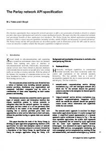
1 Introduction The PulsON 400 and PulsON 410 Ranging and Communications Modules (P400 RCM and P410 RCM) are single-board ultra wideband (UWB) radio components intended to be integrated into users’ electronic devices for enabling high precision distance measurement coupled with wireless data communications. Since the P400 and P410 interfaces are functionally equivalent, this manual refers to the devices interchangeably as an “RCM.” Any platform related differences are specifically identified. This manual specifies the programmer’s interface between the user’s Host processor and the RCM. This document provides a reference of the message structures and bit patterns in an Ethernet UDP/IP programming interface. A separate application note, Using the USB and Serial Interfaces, describes the extended header bytes and protocol required to support both the USB and 3.3V TTL Serial UART interfaces.
Fig. 1: P400 RCM (left) and P410 RCM (right) both with attached Broadspec Antenna
We recommend the software developer become familiar with the API through use of the RCM Reconfiguration and Evaluation Tool (RCM RET) application delivered with the RCM Development Kit. This MS Windows PC application provides a graphical representation of the interface data structures and allows the user to quickly become familiar with host behaviors. The RCM Quick Start Guide provides instructions for getting up and running quickly with the RCM RET. The user should reference and build upon the sample applications delivered with the RCM Development Kit.
For more information, please visit www.timedomain.com.
6
RCM API Specification
Usage Notes This section provides a short overview of key facts relative to RCM behavior and interfaces. Much of this information is covered in the RCM Quick Start Guide. Critical points for interfacing via Ethernet are repeated here for convenience. 1. Upon power-up, with or without a host connection, the RCM automatically enters UWB range response mode. It will automatically respond to a “range request” packet with its Node ID as the range target. 2. Upon successful power-up, the amber Power LED and the green Status LED should be lit with a steady glow. Other conditions indicate hardware/firmware failure. The user connects to the RCM either through an Ethernet or USB interface. The process is different for the two cases. Items 3-4 describe the USB connection process. 3. Connect the RCM to the Host using a USB 2.0 A to Micro-B cable (supplied in the P410 Development Kit). 4. As described in the RCM Quick Start Guide, the user can access the RCM using RCM RET. If RCM RET is not used, then review the document entitled Using the USB and Serial Interfaces. Items 5-9 describe the process using Ethernet. 5. Connect the RCM to the Host PC using either a crossover Ethernet cable (supplied in the P400 Development Kit) or through an Ethernet switch (some laptops have auto-sensing). 6. As covered in the RCM Quick Start Guide, the user must configure his Host PC’s TCP/IPv4 properties to a static IP address such as 192.168.1.1 with Subnet mask 255.255.255.0. The Windows Firewall must be disabled, at least for the RCM addresses of interest. 7. Determine the IP address of the RCM connected to the Host. This number is written on a label attached to the Ethernet connector on the RCM. The default UWB Node IDs will correlate with the default IP addresses. For instance, the four RCMs delivered in the Development Kit will have UWB Node IDs 100, 101, 102, and 103. These RCMs will have default IP addresses of 192.168.1.100, 192.168.1.101, 192.168.1.102, and 192.168.1.103, respectively. The RCM Node ID can be changed through this API. 8. If connecting with the RCM through RCM RET, enter the IP address of the RCM in the field entitled “Network IP Address” and click on the Connect button. If connecting with RCM RET, the user should “ping” the RCM’s Ethernet address using a command window (or terminal). 9. The user’s code should create a UDP socket targeting port 21210 on the RCM. The RCM will respond to the port that sent the message. Miscellaneous items: 10. Data transferred to/from the RCM is big-endian (network byte order). Code developed on Intel processors must swap bytes (see example code). 11. All RCM devices are slaved to their respective hosts. There is no mechanism built into the RCM to coordinate transmissions other than automatic response to targeted range requests. The hosts are responsible for coordinated transmissions (i.e., Media Access Control). Please contact Time Domain with special requests.
For more information, please visit www.timedomain.com.
RCM API Specification
7
12. The RCM measures distance through a two-way time-of-flight (TW-TOF) radio frequency (RF) ranging technique. If the antennas are altered or extra SMA cables are introduced, the range measurement will exhibit a bias based on the longer TOF of the RF pulse. Sample host interfacing software is available in C and MATLAB to help users begin developing their own UWB-enabled applications. All product documentation is posted at www.timedomain.com.
For more information, please visit www.timedomain.com.
8
RCM API Specification
2 The RCM Interface This is a high-level description of the data passed between a Host processor and the RCM. RCMs will power-up in response mode, then wait for both UWB messages arriving from other RCMs as well as commands from the Host. Figure 2 illustrates a system of 3 RCMs, two with hosts and one without a host. A high-level data flow interface is graphically depicted between one of the hosts and its co-located RCM. (A single host with Ethernet switch could support multiple RCMs wired to it via Ethernet.) The HOSTRCM interface consists of six REQUEST messages from host to RCM with their associated CONFIRM messages. In addition, there are three INFO messages that are sent to the host upon receiving UWB packets from other RCMs.
Fig. 2: Message flow - Host to RCM messages and RCM to RCM RF packets
All RCMs, including those without hosts, respond automatically to range request packets that are targeted at them. RCMs with connected hosts will automatically send data and (optionally) scan information to the host in separate UDP packets. The format of these messages is described in this document. The REQUEST and INFO messages are described in the next subsection. Appendix A contains an illustration of the data flow for a complete range/data conversation. Appendix B contains extra descriptions of many of these parameters.
For more information, please visit www.timedomain.com.
RCM API Specification
9
3 RCM API Messages 3.1 RCM_SET_CONFIG_REQUEST (0x0001) API: RCM API Message type: REQUEST (Host) Corresponding Message type: RCM_SET_CONFIG_CONFIRM (Radio) Purpose: This message configures the basic parameters in the RCM, thereby defining radio operation. Packet Definition: #
Parameter
Type
Definition
0
RCM_SET_CONFIG_REQUEST UINT16 Message type (0x0001)
1
Message ID
UINT16 Associates request to confirm and info messages
2
Node ID
UINT32 UWB ID of this radio (used for UWB range targeting.) Valid values are 0-2^32-1. By default this value will be 100 - 10X, matching the last byte of the IP address. Modifying Node ID does NOT change the IP address.
3
Pulse Integration Index (PII)
UINT16 Specifies an index, which configures the number of pulses per data symbol. Valid values are [4-10]. The default is 7 meaning 2^7 = 128 pulses per symbol.
4
Antenna Mode
UINT8 Specifies the default antenna for transmission and reception. Valid values are [0=A, 1=B, 2=TXA,RXB, 3=TXB,RXA]. In addition, setting the high order bit (0x80) of this byte enables automatic toggling of the antenna after each response by this radio. The default value is 0x00.
5
Code Channel
UINT8 Specifies the active UWB channel. Multiple ranging conversations can occur simultaneously if multiple code channels are used. Both the requester and responder radios must be configured to the same code channel for successful communication. Possible values are [0-6]. The default value is 0.
6
Antenna Delay A
INT32 Specifies the approximate time delay, in picoseconds, of the SMA cable connecting antenna A. The default value of 0ps corresponds to a Broadspec antenna o connected via 90 SMA elbow.
For more information, please visit www.timedomain.com.
10
RCM API Specification
7
Antenna Delay B
8
Flags
INT32 Specifies the approximate time delay, in picoseconds, of the SMA cable connecting antenna B. The default value of 0ps corresponds to a Broadspec antenna o connected via 90 SMA elbow. UINT16 Bit0 is the “SEND_SCAN” bit. It enables sending a SCAN_INFO with each range reception. [0=don’t send, 1=send]. The default is 0 (don’t send.) Bit1 is the FULL_SCAN bit. Default value is 0 (if sending scans, send SHORT_SCANS.) Bit2 is the “FAN_OFF” bit. It disables power to the fan. [0=on, 1=off]. By default this bit is 0 (fan is ON). Bit3 is the “SEND_SCAN_WITH_DATA” bit. It enables sending SCAN_INFO with each data-only (not range) packet. Default is 0 (do not send scan with data-only packets.) Bit4 is the “DISABLE_CRE_RANGE_MSGS” bit. It disables sending promiscuous RANGE_INFO packets with Coarse Range Estimated values with each packet received. Default is 0 (send RANGE_INFO messages with each packet received.)
9
Transmit Gain
UINT8 Specifies the pulser transmit gain from 0 (lowest) to 63 (highest). The relationship between transmit gain setting and transmit power (power to the base of the antenna) is provided in the P400 and P410 data sheets. Actual transmit ranges are provided below: P400: -14.5 to +2.1 dBm P410 standard: -31.6 to -12.64 dBm P410 optional amps: -14.5 to 0.71 dBm
10 Persist Flag
UINT8 Specifies whether this configuration record will persist through power cycling (write to FLASH memory.) Possible values are 0 (will not persist) or 1 (will persist.)
For more information, please visit www.timedomain.com.
RCM API Specification 11
3.2 RCM_SET_CONFIG_CONFIRM (0x0101) API: RCM API Message type: CONFIRM (Radio) Corresponding Message type: RCM_SET_CONFIG_REQUEST (Host) Purpose: This message is sent by the RCM to the Host in response to a RCM_SET_CONFIG_REQUEST message previously received by the RCM from the host. Its purpose is to confirm successful operation of the RCM_SET_CONFIG_REQUEST. Packet Definition: #
Parameter
Type
Definition
0
RCM_SET_CONFIG_CONFIRM (0x0101)
UINT16
Message type
1
Message ID
UINT16
Associates request to confirm packets
2
Status
UINT32
0 = successful, non-zero = error
3.3 RCM_GET_CONFIG_REQUEST (0x0002) API: RCM API Message type: REQUEST (Host) Corresponding Message type: RCM_GET_CONFIG_CONFIRM (Radio) Purpose: This is a request message sent by the Host to RCM for the current radio configuration. Packet Definition: #
Parameter
Type
Definition
0
RCM_GET_CONFIG_REQUEST (0x0002)
UINT16
Message type
1
Message ID
UINT16
Associates request to confirm packets
For more information, please visit www.timedomain.com.
12
RCM API Specification
3.4 RCM_GET_CONFIG_CONFIRM (0x0102) API: RCM API Message type: CONFIRM (Radio) Corresponding Message type: RCM_GET_CONFIG_REQUEST (Host) Purpose: This message is sent by the RCM in response to a RCM_GET_CONFIG_REQUEST from the host. It provides the current RCM configuration information. Packet Definition: #
Parameter
Type
Definition
0
RCM_GET_CONFIG_CONFIRM (0x0102)
UINT16 Message type
1
Message ID
UINT16 Associates request to confirm and info messages
2
Node ID
UINT32 UWB ID of this radio (used for UWB range targeting.) Valid values are 0-2^32-1. By default this value will be 100 - 10X, matching the last byte of the IP address. Modifying Node ID does NOT change the IP address.
3
Pulse Integration Index
UINT16 Specifies an index, which configures the number of pulses per data symbol. Valid values are [4-10]. The default is 7 meaning 2^7 = 128 pulses per symbol.
4
Antenna Mode
UINT8
Specifies the default antenna for transmission and reception. Valid values are [0=A, 1=B, 2=TXA,RXB, 3=TXB,RXA]. In addition, setting the high order bit (0x80) of this byte enables automatic toggling of the antenna after each response. The default value is 0.
5
Code Channel
UINT8
Specifies the active UWB channel. Multiple ranging conversations can occur simultaneously if multiple code channels are used. Both the requester and responder radios must be configured to the same code channel for successful communication. Possible values are [0-6]. The default value is 0.
6
Antenna Delay A
INT32
Specifies the approximate time delay, in picoseconds, of the SMA cable connecting antenna A. The default is that of the default Broadspec o antenna connected via 90 SMA elbow.
7
Antenna Delay B
INT32
Specifies the approximate time delay, in picoseconds, of the SMA cable connecting antenna B. The default is that of the default Broadspec o antenna connected via 90 SMA elbow.
For more information, please visit www.timedomain.com.
RCM API Specification 13
8
Flags
UINT16 Bit0 is the “SEND_SCAN” bit. It enables sending a SCAN_INFO with each range reception. [0=don’t send, 1=send]. The default is 0 (don’t send.) Bit1 is the FULL_SCAN bit. Default value is 0 (if sending scans, send SHORT_SCANS.) Bit2 is the “FAN_OFF” bit. It disables power to the fan. [0=on, 1=off]. By default this bit is 0 (fan is ON). Bit3 is the “SEND_SCAN_WITH_DATA” bit. It enables sending SCAN_INFO with each data-only (not range) packet. Default is 0 (do not send scan with data-only packets.) Bit4 is the “DISABLE_CRE_RANGE_MSGS” bit. It disables sending promiscuous RANGE_INFO packets with Coarse Range Estimated values with each packet received. Default is 0 (send RANGE_INFO messages with each packet received.)
9
Transmit Gain
UINT8
Specifies the pulser transmit gain from 0 (lowest) to 63 (highest). The relationship between transmit gain setting and transmit power (power to the base of the antenna) is provided in the P400 and P410 data sheets. Actual transmit ranges are provided below: P400: -14.5 to +2.1 dBm P410 standard: -31.6 to -12.64 dBm P410 optional amps: -14.5 to 0.71 dBm
10 Unused
UINT8
Reserved
11 Timestamp
UINT32 Milliseconds since RCM power-up. Note this implies a rollover approximately every 50 days.
12 Status
UINT32 0 = successful, non-zero = error
3.5 RCM_SEND_RANGE_REQUEST (0x0003) API: RCM API Message type: REQUEST (Host) Corresponding Message type: RCM_SEND_RANGE_CONFIRM (Radio) Purpose: This message commands the RCM to send a UWB range request packet (with optional data) to a targeted RCM node. Note the (optional) data sent in this packet is typically received by ALL RCM nodes within range, not just the targeted node. All RCMs
For more information, please visit www.timedomain.com.
14
RCM API Specification
that receive this data will promiscuously send this data to their respective host. The targeted node will, however, be the only node that responds with a range response. Packet Definition: #
Parameter
Type
Definition
0
RCM_SEND_RANGE_REQUEST (0x0003)
UINT16
Message type
1
Message ID
UINT16
Associates request to confirm packets
2
Responder ID
UINT32
Node ID of the range request target. A value of 2^32-1 (4294967295) indicates broadcast.
3
Antenna Mode
UINT8
Specifies the active antenna for transmission and reception. Valid values are [0=A, 1=B, 2=TXA,RXB, 3=TXB,RXA]. The default value is 0 (use antenna A for both transmissions and receptions.)
4
Reserved
UINT8
Reserved
5
Data Size
UINT16
Number of bytes to include in the range request packet. These bytes follow. Maximum = 1024. Note: the RCM transmits 32bit (4byte) words. Any partial words will be zero-filled over the air but these bits will be removed upon reception.
6
Data
N*UINT8
Data to be sent with the range request packet. Max Number of bytes is 1024.
3.6 RCM_SEND_RANGE_CONFIRM (0x0103) API: RCM API Message type: CONFIRM (Radio) Corresponding Message type: RCM_SEND_RANGE_REQUEST (Host) Purpose: This message is sent by the RCM to the HOST in response to a RCM_SEND_RANGE_REQUEST command. This response confirms the UWB range request packet was successfully sent by the RCM. Packet Definition: #
Parameter
Type
Definition
0
RCM_SEND_RANGE_CONFIRM (0x0103)
UINT16
Message type
1
Message ID
UINT16
Associates request to confirm packets
For more information, please visit www.timedomain.com.
RCM API Specification 15
2
Status
UINT32
0 = successful, non-zero = error
3.7 RCM_SEND_DATA_REQUEST (0x0004) API: RCM API Message type: REQUEST (Host) Corresponding Message type: RCM_SEND_DATA_CONFIRM (Radio) Purpose: This message commands the RCM to send a UWB data-only packet (without range request.) All RCMs within range will receive this data and promiscuously send this data to their respective host (if attached.) No automatic acknowledgement is provided for data. Packet Definition: #
Parameter
Type
Definition
0
RCM_SEND_DATA_REQUEST (0x0004)
UINT16
Message type
1
Message ID
UINT16
Associates request to confirm packets
2
Antenna Mode
UINT8
Specifies the active antenna for transmission and reception. Valid values are [0=A, 1=B, 2=TXA,RXB, 3=TXB,RXA]. The default value is 0 (use antenna A for both transmissions and receptions.)
3
Reserved
UINT8
Not used
4
Data Size
UINT16
Number of bytes to include in the data-only packet. These bytes follow. Maximum = 1024. Note: the RCM transmits 32bit (4byte) words. Any partial words will be zero-filled over the air but these bits will be removed upon reception
5
Data
N*UINT8
Data to be sent with the range request packet. Max Number of bytes is 1024.
For more information, please visit www.timedomain.com.
16
RCM API Specification
3.8 RCM_SEND_DATA_CONFIRM (0x0104) API: RCM API Message type: CONFIRM (Radio) Corresponding Message type: RCM_SEND_DATA_REQUEST (Host) Purpose: This message is sent from the RCM to the Host in immediate response to a RCM_SEND_DATA_REQUEST command. This response confirms the data-only packet was successfully sent by the RCM. Packet Definition: #
Parameter
Type
Definition
0
RCM_SEND_RANGE_CONFIRM (0x0104)
UINT16
Message type
1
Message ID
UINT16
Associates request to confirm packets
2
Status
UINT32
0 = successful, non-zero = error
3.9 RCM_SET_RESPONSE_DATA_REQUEST (0x0005) API: RCM API Message type: REQUEST (Host) Corresponding Message type: RCM_SET_RESPONSE_DATA_CONFIRM (Radio) Purpose: This message allows the Host to set the data buffer in the RCM range response packet. This data will be transmitted by the RCM whenever it sends a range response packet. This data buffer will remain in effect until changed by the host. Upon boot this buffer will be empty. Packet Definition: #
Parameter
Type
Definition
0
RCM_SET_RESPONSE_DATA_RE QUEST (0x0005)
UINT16
Message type
1
Message ID
UINT16
Associates request to confirm packets
2
Reserved
UINT16
Reserved
3
Data Size
UINT16
Number of bytes to include in each range response packet. These actual bytes follow. Maximum = 1024.
For more information, please visit www.timedomain.com.
RCM API Specification 17
4
Data
N*UINT8
Data to be sent with the range request packet. Extra bytes above will be ignored. Note: the RCM transmits 32bit (4byte) words. Any partial words will be zero-filled over the air but these bits will be removed upon reception
3.10 RCM_ SET_RESPONSE_DATA_CONFIRM (0x0105) API: RCM API Message type: CONFIRM (Radio) Corresponding Message type: RCM_SET_RESPONSE_DATA_REQUEST (Host) Purpose: This message is sent by the RCM to the Host in immediate response to a RCM_SET_RESPONSE_DATA_REQUEST command. This response confirms the buffer was successfully written. Packet Definition: #
Parameter
Type
Definition
0
RCM_SET_RESPONSE_DATA_CO NFIRM (0x0105)
UINT16
Message type
1
Message ID
UINT16
Associates request to confirm packets
2
Status
UINT32
0 = successful, non-zero = error
3.11 RCM_GET_STATUSINFO_REQUEST (0xF001) API: RCM API Message type: REQUEST (Host) Corresponding Message type: RCM_GET_STATUSINFO_CONFIRM (Radio) Purpose: This message prompts the RCM to send the Host a data structure describing the hardware and software version numbers as well as other RCM status information. Packet Definition: #
Parameter
Type
Definition
0
RCM_GET_STATUSINFO_REQUE ST (0xF001)
UINT16
Message type
1
Message ID
UINT16
Associates request to confirm packets
For more information, please visit www.timedomain.com.
18
RCM API Specification
3.12 RCM_GET_ STATUSINFO_CONFIRM (0xF101) API: RCM API Message type: CONFIRM (Radio) Corresponding Message type: RCM_GET_STATUSINFO_REQUEST (Host) Purpose: This message is sent by the RCM to the Host in immediate response to a RCM_GET_VERSION_REQUEST command. This response provides a list of the hardware and software version numbers as well as other RCM status information. Packet Definition: #
Parameter
Type
Definition
0
RCM_GET_STATUSINFO_CONFIR M (0xF101)
UINT16
Message type
1
Message ID
UINT16
Associates request to confirm packets
2
RCM Version Major
UINT8
RCM embedded major version number
3
RCM Version Minor
UINT8
RCM embedded minor version number
4
RCM Version Build
UINT16
RCM embedded build version number
5
UWB Kernel Major
UINT8
kernel code major version number
6
UWB Kernel Minor
UINT8
kernel code minor version number
7
UWB Kernel Build
UINT16
kernel code build version number
8
FPGA Firmware Version
UINT8
Firmware version number
9
FPGA Firmware Year
UINT8
Firmware year
10 FPGA Firmware Month
UINT8
Firmware month
11 FPGA Firmware Day
UINT8
Firmware day
12 Serial Number
UINT32
Device serial number
13 Board Revision
UINT8
PCB revision – a single ASCII character
14 Power-On BIT Test Result
UINT8
Built-in Test Results, non-zero indicates BIT failure.
15 Board Type
UINIT8
1 – P400, 2 – P410
16 Transmitter Configuration
UINT8
0 – FCC compliant 1 – FCC compliant, transmit amplifiers installed 2 – EU compliant
For more information, please visit www.timedomain.com.
RCM API Specification 19
17 Temperature
INT32
18 Status
UINT32
o
Board temp in 0.25 C (divide this number by o 4 to produce floating point C.). Status
3.13 RCM_REBOOT_REQUEST (0xF002) API: RCM API Message type: REQUEST (Host) Corresponding Message type: RCM_REBOOT_CONFIRM (Radio) Purpose: This message causes the RCM to reboot, adopting configuration parameters saved to flash. Packet Definition: #
Parameter
Type
Definition
0
RCM_REBOOT_REQUEST (0xF002)
UINT16
Message type
1
Message ID
UINT16
Associates request to confirm packets
3.14 RCM_REBOOT_CONFIRM (0xF102) API: RCM API Message type: CONFIRM (Radio) Corresponding Message type: RCM_REBOOT_REQUEST (Host) Purpose: This message is sent by the RCM to the Host in immediate response to a RCM_REBOOT_REQUEST command. Immediately after sending this message to the host, the RCM will reboot. Packet Definition: #
Parameter
Type
Definition
0
RCM_REBOOT_CONFIRM (0xF102)
UINT16
Message type
1
Message ID
UINT16
Associates request to confirm packets
For more information, please visit www.timedomain.com.
20
RCM API Specification
3.15 RCM_SET_OPMODE_REQUEST (0xF003) API: RCM API Message type: REQUEST (Host) Corresponding Message type: RCM_SET_OPMODE_CONFIRM (Radio) Purpose: This message can be used to transition the RCM to RCM mode. Packet Definition: #
Parameter
Type
Definition
0
RCM_SET_OPMODE_REQUEST (0xF003)
UINT16
Message type
1
Message ID
UINT16
Associates request to confirm packets
2
Operational Mode
UINT32
0: RCM
3.16 RCM_ SET_OPMODE _CONFIRM (0xF103) API: RCM API Message type: CONFIRM (Radio) Corresponding Message type: RCM_SET_OPMODE_REQUEST (Host) Purpose: This message is sent by the RCM to the Host in response to a RCM_SET_OPMODE_REQUEST command indicating the status of the request. Packet Definition: #
Parameter
Type
Definition
0
RCM_OPMODE_CONFIRM (0xF103)
UINT16
Message type
1
Message ID
UINT16
Associates request to confirm packets
2
Operational Mode
UINT32
New Operational Mode
2
Status
UINT32
A zero indicates success. Nonzero implies illegal transition.
For more information, please visit www.timedomain.com.
RCM API Specification 21
3.17 RCM_BIT_REQUEST (0xF008) API: RCM API Message type: REQUEST (Host) Corresponding Message type: RCM_BIT_CONFIRM (Radio) Purpose: This message prompts the RCM to perform a BIT (Built-In-Test), returning results in the RCM_BIT_CONFIRM message. Packet Definition: #
Parameter
Type
Definition
0
RCM_BIT_REQUEST (0xF008)
UINT16
Message type
1
Message ID
UINT16
Associates request to confirm packets
3.18 RCM_ BIT_CONFIRM (0xF108) API: RCM API Message type: CONFIRM (Radio) Corresponding Message type: RCM_BIT_REQUEST (Host) Purpose: This message is sent by the RCM to the Host in response to a RCM_BIT_REQUEST command. This response provides the status of the BIT (Built-InTest). Packet Definition: #
Parameter
Type
Definition
0
RCM_BIT_CONFIRM (0xF108)
UINT16
Message type
1
Message ID
UINT16
Associates request to confirm packets
2
BIT Status
UINT32
Return status of the Built-In-Test. Zero indicates no errors detected.
For more information, please visit www.timedomain.com.
22
RCM API Specification
3.19 RCM_SET_SLEEPMODE_REQUEST (0xF005) API: RCM API Message type: REQUEST (Host) Corresponding Message type: RCM_SLEEPMODE_CONFIRM (Radio) Purpose: This message causes the RCM to transition to a low power mode. Packet Definition: #
Parameter
Type
Definition
0
RCM_SLEEPMODE_REQUEST (0xF005)
UINT16
Message type
1
Message ID
UINT16
A tracking number used to associate Host REQUEST messages to RCM CONFIRM messages.
2
Sleep Mode
UINT32
Specifies the transition state. 0: ACTIVE (required for transition out of any low-power state.) 1: IDLE (turns off UWB acquisition. Leaves all interfaces active.) 2: ETHERNET (power down most components but leave the Ethernet interface enabled.) 3:SERIAL (power down most components including the Ethernet interface.)
3.20 RCM_SET_SLEEPMODE_CONFIRM (0xF105) API: RCM API Message type: CONFIRM (Radio) Corresponding Message type: RCM_SLEEPMODE_REQUEST (Host) Purpose: This message is sent by the RCM to the Host in immediate response to a RCM_SLEEPMODE_REQUEST command. This response verifies the RCM received and the request. Packet Definition: #
Parameter
Type
Definition
0
RCM_SLEEPMODE_REQUEST (0xF005)
UINT16
Message type
1
Message ID
UINT16
A tracking number used to associate Host REQUEST messages to RCM CONFIRM messages.
For more information, please visit www.timedomain.com.
RCM API Specification 23
2
Status
UINT32
Specifies the execution status. Status=0 indicates success.
3.21 RCM_RANGE_INFO (0x0201) API: RCM API Message type: INFO (Radio) Corresponding Message type: none Purpose: This message is sent by the local requesting RCM to its Host at the end of a full UWB ranging conversation or timeout. Timeouts, indicated in the status field, can occur if the targeted responder failed to receive, or the requester failed to acquire the response packet. Note: this structure was modified and extended in RCM v2.0 to include Coarse Range Estimate (CRE). If the RCM was able to generate a CRE from any received UWB packet, and the RCM is connected to a host, it will send an RCM_RANGE_INFO message to the host. Setting the DISABLE_CRE_RANGE_MSGS bit in the configuration flags (RCM_SET_CONFIG_REQUEST) will disable this behavior. Packet Definition: #
Parameter
Type
Definition
0
RCM_RANGE_INFO (0x0201)
UINT16
Message type
1
Message ID
UINT16
Identifier to correlate range requests with info messages
2
Responder ID
UINT32
Node ID of the UWB module that sent the range response.
3
Range Status
UINT8
0 = Success Some failure modes can combine in a mask with these bits set: bit0 = TIMEOUT Failure bit1 = Request LED Failure bit2 = Response LED Failure bit5 = Range out of bounds failure bit6 = Coarse range only other = TBD
For more information, please visit www.timedomain.com.
24
RCM API Specification
4
Antenna Mode
UINT8
Specifies the antenna ports used during this range conversation. The lower nibble describes the antenna configuration used by the requester, and the upper nibble the antenna configuration used by the responder. Valid values for each nibble are: 0 = Transmit and Receive on the A port, 1 = Transmit and Receive on the B port, 2 = TX on A, RX on B, 3 = TX on B, RX on A.
5
Stopwatch Time
UINT16
Duration of the range conversation in milliseconds.
6
Precision Range Measurement (PRM)
UINT32
Raw precise distance in millimeters between UWB modules based on a two-way Time of Flight (TOF) measurement.
7
Coarse Range Estimate (CRE)
UINT32
Raw coarse distance in millimeters based on direct path signal strength. Note this value is recalibrated to the PRM value each time a PRM of the link is measured.
8
Filtered Range Estimate (FRE)
UINT32
Filtered distance in millimeters based on the combination of PRM and CRE values passed through a recursive optimal Kalman estimator with two state variables (r & rdot).
9
PRM Error (PRME)
UINT16
Estimated standard deviation error, in millimeters, of associated PRM value. Estimated from pulse waveform signature.
10 CRE Error (CREE)
UINT16
Estimated standard deviation error, in millimeters, of associated CRE value.
11 FRE Error (FREE)
UINT16
Estimated standard deviation error, in millimeters, of associated FRE value. Derived by the filter.
12 Filtered Range Velocity (FRV)
INT16
Estimated radial velocity in millimeters per second
13 FRV Error (FRVE)
UINT16
Estimated standard deviation, in millimeters per second, of the FRV value.
14 Range Measurement Type
UINT8
Specifies the valid components of this message. 1 = Precision Range Measurement (PRM) 2 = Coarse Range Estimate (CRE) 4 = Filtered Range Estimate (FRE)
15 reserved
UINT8
Alignment
For more information, please visit www.timedomain.com.
RCM API Specification 25
These characteristics refer to the requester’s received scan: 1 = SATURATED 2 = SCAN WINDOW TOO SHORT 4 = SNR TOO LOW 8 = LINE OF SIGHT (LOS) 16 = NON-LINE OF SIGHT (NLOS) These characteristics refer to the responder’s received scan, or, for a CREonly range, the local RCM’s received scan: 1 = SATURATED 2 = SCAN WINDOW TOO SHORT 4 = SNR TOO LOW 8 = LINE OF SIGHT (LOS) 16 = NON-LINE OF SIGHT (NLOS)
16 Requester LED Flags
UINT16
17 Responder LED Flags
UINT16
18 Channel Rise
UINT16
A relative measure of the amount of time from start of the leading edge of the received channel to a local maximum. Short rise times indicate line-of-sight channels while long (slow) rise times indicate NLOS channels.
19 Vpeak
UINT16
The absolute maximum value in the leading edge window of the received waveform. This value is used to determine the Coarse Range Estimate.
20 Coarse TOF
INT32
18 Timestamp
UINT32
The range measurement before applying leading edge offsets. Milliseconds from boot to time of range conversation completion.
3.22 RCM_DATA_INFO (0x0202) API: RCM API Message type: INFO (Radio) Corresponding Message type: none Purpose: This message is sent by the local connected RCM to its Host whenever the RCM receives a UWB message. Note that a promiscuous RCM will “overhear” two packets per range conversation: one is the request packet, and the other the response packet. If these packets contain user data then the promiscuous RCM will send two of RCM_DATA_INFO packets to its host (if attached). This enables the RCM to support “sideways” data transmission outside the range request/response pair. Packet Definition: # 0
Parameter RCM_DATA_INFO (0x0202)
Type UINT16
Definition Message type
For more information, please visit www.timedomain.com.
26
RCM API Specification
1
Message ID
UINT16
Identifier to correlate data packets across radios
2
Source ID
UINT32
Node ID of the UWB module that sent the data.
3
Channel Rise
UINT16
A relative measure of the amount of time from start of the leading edge of the received channel to a local maximum. Short rise times indicate line-of-sight channels while long (slow) rise times indicate non-line of sight channels.
4
Vpeak
UINT16
The absolute maximum value in the leading edge window of the received waveform. This value is used to determine the Coarse Range Estimate.
5
Timestamp
UINT32
Milliseconds from boot to time of data reception.
6
Antenna ID
UINT8
Indicates which antenna was used to receive this data (0=A, 1=B)
7
Reserved
UINT8
Reserved
8
Data Size
UINT16
Number of bytes received. These bytes follow.
9
Data
N*UINT8
Data bytes received. Max will be 1024.
3.23 RCM_SCAN_INFO (0x0203) API: RCM API Message type: INFO (Radio) Corresponding Message type: none Purpose: This message is optionally sent by the RCM to the Host whenever it receives an RF packet. This is debug information only and is not sent by default. The default state is defined by the RCM_SET_CONFIG_REQUEST message. Packet Definition: #
Parameter
Type
Definition
0
RCM_SCAN_INFO (0x0203)
UINT16
Message type
1
Message ID
UINT16
Identifier used to correlate transmissions with info messages
2
Source ID
UINT32
Node ID of the transmitting radio
For more information, please visit www.timedomain.com.
RCM API Specification 27
3
Antenna ID
UINT8
Designator of receiving antenna (0=A, 1=B)
4
Reserved
UINT8
Reserved
5
LED Flags
UINT16
6
Channel Rise
UINT16
A relative measure of the amount of time from start of the leading edge of the received channel to a local maximum. Short rise times indicate line-of-sight channels while long (slow) rise times indicate non-line of sight channels.
7
Vpeak
UINT16
The absolute maximum value in the leading edge window of the received waveform. This value is used to determine the Coarse Range Estimate.
8
Timestamp
UINT32
Milliseconds from boot to time of data reception.
9
Leading Edge Offset
10 Lockspot Offset
11 Number of Scan Samples
12 Scan Data
These characteristics refer to the received scan: 1 = SATURATED 2 = SCAN WINDOW TOO SHORT 4 = SNR TOO LOW 8 = LINE OF SIGHT (LOS) 16 = NON-LINE OF SIGHT (NLOS)
INT32
Offset from first sample where radio found leading edge of pulse.
INT32
Offset from first sample where radio locked on the pulse.
UINT32
INT32
The number of data points (UINT32) that follow. Scan values collected by the radio.
For more information, please visit www.timedomain.com.
28
RCM API Specification
3.24 RCM_FULL_SCAN_INFO (0xF201) API: RCM API Message type: INFO (Radio) Corresponding Message type: none Purpose: This message is optionally sent by the RCM to the Host whenever it receives an RF packet. This is debug information only and is not sent by default. The default state is defined by the RCM_SET_CONFIG_REQUEST message. Due to the number of samples in a full waveform scan, the waveform scan data is split into many RCM_FULL_SCAN_INFO messages. Packet Definition: #
Parameter
Type
Definition
0
RCM_FULL_SCAN_INFO (0xF201)
UINT16
Message type
1
Message ID
UINT16
Identifier used to correlate transmissions with info messages
2
Source ID
UINT32
Node ID of the transmitting radio
3
Timestamp
UINT32
Milliseconds from boot to time of data reception.
4
Channel Rise
UINT16
A relative measure of the amount of time from start of the leading edge of the received channel to a local maximum. Short rise times indicate line-of-sight channels while long (slow) rise times indicate non-line of sight channels.
5
Vpeak
UINT16
The absolute maximum value in the leading edge window of the received waveform. This value is used to determine the Coarse Range Estimate.
6
Reserved
UINT32
Reserved
7
Leading Edge Offset
INT32
Offset from first sample where radio found leading edge of pulse.
8
Lock Spot Offset
INT32
Offset from first sample where radio locked on the pulse.
9
Scan Start
INT32
The start position of the waveform scan relative to the lock spot in picoseconds.
10 Scan Stop
INT32
The stop position of the waveform scan relative to the lock spot in picoseconds.
For more information, please visit www.timedomain.com.
RCM API Specification 29
11 Scan Step
UINT16
The amount of time between each sample in bins. By default this is 32 bins equating to about 61 picoseconds between samples.
12 Reserved
UINT16
Reserved
13 Antenna ID
UINT8
Designator of receiving antenna (0=A, 1=B)
14 Operational Mode
UINT8
Specifies the mode of the radio when this scan was collected. [RCM=0]
15 Number of Samples in this Message
UINT16
The number of samples that follow in this message (UDP or Serial).
16 Total Number of Scan Samples
UINT32
The total number of samples in the full scan.
17 Message Index
UINT16
The index of this message within the sequence of RCM_FULL_SCAN_INFO messages.
18 Total Number of Messages
UINT16
The total number of RCM_FULL_SCAN_INFO messages in the entire scan.
19 Scan Data
350*INT32 Scan values collected by the radio.
For more information, please visit www.timedomain.com.
30
RCM API Specification
Appendix A: Anatomy of a Complete Range Conversation Figure A-1 illustrates the process flow when measuring a single PRM from the point of view of (user) host1 connected to ranging radio RCM1.
UDP, USB, or Serial
UWB RF
UDP, USB, or Serial
Fig. A-1: Precision Range Measurement (PRM) process flow diagram
1 REQUEST: HOST1 issues a RCM_SEND_RANGE_REQUEST message to RCM1, which is connected via Ethernet, USB, or Serial. 2 REQUEST PACKET: RCM1 emits a UWB packet in range request form targeted at RCM2. 3 CONFIRM: RCM1 responds with a RCM_SEND_RANGE_CONFIRM message. 4 RESPONSE PACKET: RCM2, if targeted by HOST1 as the RESPONDER, immediately responds with a UWB response packet. 5 DATA INFO: Any user data in the request packet is reported to HOST2 (if connected.) 6 SCAN INFO: If configured to send scan info, RCM2 will send SCAN_INFO data to HOST2. 7 SCAN INFO: Upon reception of the response from RCM2 and if configured to send scan info, RCM1 will report scan data to HOST1. 8 DATA INFO: Any RESPONSE_DATA in the response packet will be reported to HOST1. 9 RANGE INFO: Finally RCM1 will compute precision and filtered distance and report a RCM_RANGE_INFO message to HOST1. NOTE1: DATA INFO is reported to ANY host connected to ANY RCM that “overhears” a packet (promiscuous operation.)
For more information, please visit www.timedomain.com.
RCM API Specification 31
NOTE2: RCM_SCAN_INFO is only sent to the host if the host has pre-configured the RCM to send it. NOTE3: A single MESSAGE_ID in HOST1’s originating REQUEST message will be echoed at all end-points of this information flow. All RANGE, DATA, and SCAN INFO messages, at source, sink, and promiscuous hosts, can be tied together using this single MESSAGEID. Thus MESSAGE_ID becomes an important tool when logging data and post-processing for full system connectivity and range analysis. In fact, the host should rely on MESSAGE_ID for correlating messages, rather than any particular order or timing of RANGE, DATA, and SCAN INFO messages.
For more information, please visit www.timedomain.com.
32
RCM API Specification
Appendix B: Parameter Descriptions The following sections provide additional UWB or system-level detail for API parameters described in Section 3.
B.1 Message ID The Message ID parameter is a convenient way for the system integrator to keep track of messages and associated responses. The user typically specifies a unique Message ID for each REQUEST command sent to one or more local RCMs. The RCM will echo this Message ID in each of its responses. In addition, upon receipt of RANGE_INFO, DATA_INFO, and SCAN_INFO messages the Message ID in each of these messages will uniquely match the RCM_SEND_RANGE_REQUEST message used to generate these INFO packets. Typical host software for data collection will increment Message ID between each RANGE_REQUEST and use the Message ID to help relate RANGE, DATA, and SCAN info to a particular RANGE_REQUEST, as well as isolate and debug dropped Ethernet/UDP messages.
B.2 Pulse Integration Index (PII) This value determines the number of pulses used in each radio symbol or scan point. Larger PII values result in a higher signal-to-noise ratio (SNR) with longer distance operation at the expense of slower ranging and data rates. All RCM nodes must be pre-configured with identical PII values in order to establish communication and ranging. The user configures the “power of 2” of the pulse integration value. For example, a configured value of PII=7 results in the transmitting node sending 128 pulses per symbol and the receiving node expecting 128 pulses per symbol. If the user needs distance more than speed, he or she can reconfigure PIIs of both transmitter and receiver to 8, providing 2x the SNR in each symbol resulting in approximately 40% more distance in line-of-sight conditions. The ranging conversation time will roughly double with each increment of PII. The entire range of PII values with consequential distances, data rates, and ranging measurement update times are provided in Figure B-1. The maximum distance assumes US Federal Communications Commission (FCC)-compliant power levels and standard Broadspec antennas. Range measurement duration is the stopwatch time from request packet start to response packet received. This does not include overhead due to communication and processing by the user host computer between successive packet reception and transmissions.
For more information, please visit www.timedomain.com.
RCM API Specification 33
PII 4 5 6 7 8 9 10
Max Range* (meters) 35 60 88 125 177 250 354
Data rate: (bps) 632k 316k 158k 79k 39.5k 19.7k 9.86k
Precision Range Measurement (time, rate) 6.5 ms, 154 Hz 8.5 ms, 118 Hz 12.5 ms, 80 Hz 20 ms, 50 Hz 36 ms, 28 Hz 67 ms, 15 Hz 132 ms, 8 Hz
Fig. B-1: Pulse Integration Index (PII) settings and resulting distance, data rate, and range measurement rates for the RCM at transmit power of -14.5 dBm *Point-to-Point Line-of-Sight estimate
B.3 Antenna Mode The P RCM supports two antenna ports. The port nearest the corner of the board is typically designated as the “A” port. By default the RCM uses the A port. The user can define which port is to be used for transmit and which is to be used for receive. It is possible to use the same antenna for both transmission and reception. A special antenna mode, Mode 128, is available to support automatic toggling of the default antenna port after each range response. This allows one or more host-controlled anchor RCMs to iteratively measure distances to two antenna points connected to a responder, without requiring host support for the responder. This definition is specified in the following Host to RCM commands: RCM_SET_CONFIG_REQUEST RCM_SEND_RANGE_REQUEST RCM_SEND_DATA_REQUEST The following table illustrates the values:
Mode Value
Transmit Port
Receive Port
0
A
A
1
B
B
2
A
B
3
B
A
128
Auto-Toggle after Response
Table B-1: Antenna mode configuration settings for the RCM
For more information, please visit www.timedomain.com.
34
RCM API Specification
B.4 Code Channel Seven separate and independent communications channels have been provided. RCMs only support one channel at a time. RCMs receiving on a particular code channel will not hear those transmitting on a different channel. The channels are designated as channels 0 through 6. The default channel is channel 0. These channels allow the user to implement a code-division multiple access (CDMA) network supporting up to 7 different “cells”, or a unique beacon code used for coordination which does not interfere with sub-cells. The user is responsible for coordinating these code channels. Many more code channels are possible. The user should contact Time Domain for additional or unique code channel enhancements.
B.5 Antenna Delay A & B The RCMs implement a Two-Way Time-of-Flight (TW-TOF) ranging technique. The result of a ranging conversation is the time it takes a pulse to travel from the pulser circuit of the requester to the sampling circuit of the responder and back. This value is divided by two and multiplied by the speed of light to return distance. Typically the user wants a distance measurement relative to the antennas of the radios. The RCMs have been calibrated by default to presume a zero Antenna Delay when using the default Broadspec antennas with a simple 90 degree elbow SMA connector. If the system integrator changes to a new UWB antenna or uses a SMA coaxial cable extension, (for instance to keep the RCM inside an electronics box with the antenna outside) then the range value reported would increase proportional to this extended TOF. The user can either consistently subtract the extra bias in his software or reconfigure the RCM (using the RCM_SET_CONFIG_REQUEST) to store this bias using these registers.
B.6 Timestamp Time stamp is the number of milliseconds that have elapsed since the latest RCM power-up. This parameter is not used by the RCM, but is provided to enable the system integrator to establish when the range was collected or data was received. Note this is an interrupt-driven CMOS timestamp with millisecond accuracy. It is not based on picosecond timing triggers in the RF front end.
B.7 Vpeak and Channel Rise Time Vpeak and Channel Rise Time are quality metrics that do not require a full range conversation. These metrics accompany any range, data, or scan message whenever the RCM receives a packet. Vpeak is a measure of the maximum absolute value of the amplitude measured just after the leading edge offset. This peak value is an improved form of Relative Signal Strength (RSS) and rarely suffers from multipath fading or construction. It can be used to estimate distance from a receive-only signal, increasing the capacity and scalability of networks of RCM nodes. In fact this is the basis for the
For more information, please visit www.timedomain.com.
RCM API Specification 35
Coarse Range Estimate (CRE). The Channel Rise Time metric is a measure of the time required for the direct path pulse to rise from noise to complete signal. Line-of-sight signals have very short rise times. Through-wall or reflected signals lose some of their high frequency content and therefore the rise time will increase. Channel rise values more than 2 indicate a NLOS channel and a loss in range precision. These metrics are meant to provide two capabilities. First, Vpeak can be used as a coarse, receiveonly distance measurement. Due to multipath resistance it will be more accurate than a narrowband distance based on signal strength, and channel quality can be used to de-rate non-Line of Sight measurements. Second, Channel Rise Time is the fundamental metric used in our TW-TOF range error estimate. When a host overhears a transmission from a distant node he can use this metric to estimate the range error he would get if he sent a range request to that node. This will help optimize the scheduling in ad-hoc tracking networks.
SIGNAL LED Noise
Fig. B-2: Illustration of Leading Edge, Signal, and Noise values in the pulse scan.
B.8 Precision Range Measurement (PRM) and PRM Error Estimate (PRME) PRM is the Two-Way Time-of-Flight distance between the requesting and responding RCMs. More precisely it is a measure of the most direct path of a RF pulse from pulser to sampler, after subtraction of the antenna delay offsets. After calibration with respect to antenna delay, the measurement should be considered the distance from antenna phase centers. The phase center point for the standard BroadSpec™ antenna is shown in Figure B-3. PRM is reported in millimeters.
For more information, please visit www.timedomain.com.
36
RCM API Specification
Radiating Point
Fig. B-3: Broadspec UWB antenna with radiating point indicated
PRME, returned with each PRM, is an estimate of the standard deviation of the associated PRM. This metric is pulled from a look-up table indexed by features of the incident pulse such as Channel Rise and Vpeak. The correlation analysis was performed in an indoor/outdoor propagation campaign in and around a standard office environment.
B.9 Coarse Range Estimate (CRE) and Coarse Range Error Estimate (CREE) The RCM 2.0 firmware features a number of advanced measurements in addition to PRM. Any time an RCM receives a packet, the waveform scan is analyzed to provide CRE through relative signal strength measure of the earliest, most direct path pulse. Even though pulsed-RF has the advantage of multipath separation, this technique can suffer from errors due to channel and antenna pattern changes. These changes are inherent in distributed dynamic localization systems. This problem can be overcome through occasional calibration through PRM ranging. CRE is only valid in Line-ofSight (LOS), non-saturated conditions (saturation occurs even if the transmitting radio is at the lowest transmit gain and the receiver is LOS and within 16 feet (4.9m). Specifically CRE values will be automatically generated if and only if: 1. The SEND_CRE flag is enabled in the RCM configuration 2. The CRE has been calibrated through at least one PRM measurement to the target node ID 3. The RF channel is not SATURATED as determined by the radio firmware (and reported in the LEDflags field) 4. The RF channel is Line-of-Sight as determined by the radio firmware (and reported in the LEDflags field) CRE Error (CREE) is also reported with each CRE to support weighted combination of CRE with other distance measurements (such as PRM). These values are generated by a lookup table informed by the correlation between SNR and CRE Error.
For more information, please visit www.timedomain.com.
RCM API Specification 37
B.10 Range Filter The FRE and FRV, as well as their associated error estimates FREE and FRVE, are the result of a recursive optimal (Kalman) estimator in the RCM firmware. This Kalman filter is based on two state variables range and range velocity. As shown in Figure B-4, a unique Kalman filter instance is created and maintained for each unique PRM range target. Whenever a new PRM or valid CRE measurement is generated, this filter performs a weighted combination of these measurements with an internal linear motion model of distance. FRE Error (FREE) and FRV Error (FRVE) are generated and reported as a byproduct of this filter. The KF configuration parameters have been internally adjusted to optimize FRE and FRV operation on a group of vehicles moving 25 kmph or slower. When occasional PRMs are combined with frequent CRE measurements (which result from promiscuous listening) through the embedded filter, the PRM rate requirement is greatly reduced. See B. Dewberry and W. Beeler, “Increased Ranging Capacity using Ultra-Wideband Direct-path Pulse Signal Strength with Dynamic Recalibration”, ION PLANS April 2012.
Fig. B-4: Range Filter process
B.11 Leading Edge Offset, Lockspot Offset, Number of Scan Samples, and Scan Data These parameters are all associated with the direct sequential scan of the pulse waveform and subsequent computation of the direct path. In order for the RCM to compute an accurate TOF it must measure the offset from the lockspot, which is often on a multipath reflection, to the most direct pulse. The RCM performs a scan relative to the lockspot, then measures the offset and updates the range estimate. The resolution of the scan waveform is 61ps. The leading edge offset is the index in this scan where the system determined the time-of-arrival (TOA) of this pulse. The lockspot offset is the relative index where the radio acquired. The RCM_SCAN_INFO is not required to use the RCM. It is provided to allow the user to investigate (optionally) the channel impulse response around the direct path and make conclusions
For more information, please visit www.timedomain.com.
38
RCM API Specification
about the range or channel multipath content. These parameters are illustrated in the Figure B-5. Leading Edge
Lock Spot
Lockspot Offset Leading Edge Offset
#1
138 measurement taken at increments of 61ps
#138
Fig. B-5: Waveform scan showing Lockspot, Lockspot Offset, Leading Edge and Leading Edge Offset
B.12 LED Flags In pulsed RF radios the short window just after the Leading Edge offset contains much of the information required to characterize the RF channel. Four such characterizations are illustrated in Figure B-6 below. Flags indicating SATURATION, NLOS, and LOS conditions are generated by the radio firmware any time a new packet is received and optionally reported to the host in RCM_RANGE_INFO and RCM_SCAN_INFO messages.
For more information, please visit www.timedomain.com.
RCM API Specification 39
Fig. B-6: Using the Direct Path Window to characterize the RF channel
B.13 Power Down States Overview It is always useful to minimizing power consumption of a system. To that end, Time Domain has identified different operating states and has provided a number of API commands that enable operation in a variety of sleep states. In these sleep states, the unit will de-energize various circuits. The deeper the sleep state, the less power the RCM will consume. It will also take a few milliseconds for the RCM to transition to and from these sleep states. In general, the deeper the sleep state, the longer it will take to enter and emerge from the requested state. Finally, once the unit is in a sleep state, it will no longer be possible to generate scans or change radar parameters. Attempting to do so will generate an error message.
Description of Active and Sleep Modes The power modes are described below.
For more information, please visit www.timedomain.com.
40
RCM API Specification
INITIAL BOOT: when the RCM is initially powered it will act as radio. It will idle with the RF receive circuitry on and search for incoming RF packets. Once a connection is made to the RCM either through an RCM API command or by connecting with RCM RET, the user can change parameters, receive data, respond to range requests, send data or send a range request. ACTIVE (requesting): Once the user initiates a range request, it will be engage the transmit circuits, launch the request packet and engage the receive circuits. The RCM will experience its maximum power consumption in this state. ACTIVE (receiving/responding): The unit will active the receive circuits and wait for incoming messages. The RCM will experience very high power consumption slightly less than during Active (requesting). IDLE: In this state, the transmit and receive circuitry and baseband logic are halted. This reduces the dynamic power consumption of the baseband FPGA. Also, the low noise receive amplifiers and transmit amplifiers are disabled. The RCM software can respond to API commands over either the Ethernet or Serial interfaces. The radio can transition from IDLE mode to ACTIVE mode very rapidly. STANDBY_E: This state offers additional power savings over the IDLE mode by clock-gating the FPGA thereby eliminating dynamic power consumption, and disabling power to the UWB RF Front End chips. As in the IDLE mode, the RCM software is able to respond to API commands over either Ethernet or the Serial port interfaces. STANDBY_S: This state is identical to STANDBY_E except the Ethernet PHY chip is powered down for a slight additional power savings. As a result, when in this mode the RCM software is only able to respond to API commands over the Serial port. Typical power consumption for each power mode and the time required to transition into and out of the modes are shown on the P400/P410 Data Sheets.
For more information, please visit www.timedomain.com.


![GC-100 API Specification [pdf]](https://m.moam.info/img/260x300/gc-100-api-specification-pdf_59f31ebb1723dd05d49d7298.jpg)