mined by the angle of the cables, the suspended weight, and the ... stiffness in a lightweight frame. ... be made extremely lightweight compared to conventional.
RCS-Based RoboCrane Integration Roger Bostelman, Adam Jacoff, Nicholas Dagalakis, James Albus Intelligent Systems Division National Institute of Standards and Technology Gaithersburg, Maryland 20899
Abstract
1.0 Introduction
The Intelligent Systems Division (ISD) of the National Institute of Standards and Technology (NIST) has been researching new concepts in robotic cranes for several years. These concepts use the basic idea of the Stewart platform parallel link manipulator. The unique feature of the NIST approach is to use cables as the parallel links and to use winches as the actuators. Based on this idea, a revolutionary new type of robot crane has been developed and aptly named the RoboCrane. The RoboCrane provides six degree-of-freedom load stabilization and maneuverability. This is accomplished through the following control modes: master/slave; joystick input; operator panel input; preprogrammed trajectory following (teach programing, graphical off-line programing, or part programing); and sensor based motion compensation. The current control system includes both the controller and user interface within the same control level, which makes controller enhancements and modifications difficult and error prone. A Real-time Control System (RCS) [1] is currently being developed to include the above control modes, while providing an open systems architecture. This supports hierarchical control modules, along with a separate user interface. A remote telepresence system is also being implemented to provide foveal/peripheral stereo images and other necessary data to enable a remote operator to perform a variety of tasks with the RoboCrane.
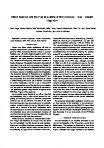
The RoboCrane prototype (FIGURE 1) was first developed by NIST in the late 1980's [2]. A NIST program on robot crane technology, sponsored by the Defense Advanced Research Projects Agency (DARPA), developed and tested several potential robot crane designs to determine the desired performance characteristics of a proposed robot crane. Initial testing of these prototypes showed that a six cable design results in a remarkably stable platform capable of performing accurate six degree-of-freedom (DOF) manipulations. This stabilized platform can be used to improve typical crane operations or as a maneuverable robot/tool base.
The objective of this paper is to describe past and future efforts toward integration of an RCS open system architecture controller into the RoboCrane Integration Testbed (RIT). An RCS-based Robo-Crane controller will allow for continuing research into parallel-link manipulator controllers and application oriented controller capabilities. Specifically, this paper introduces the RoboCrane concept, describes the current control system, the envisioned RCSbased RoboCrane control system, and the intended integration procedure. Keywords: Real-Time Control System (RCS), open system architecture, parallel link manipulator, Stewart platform devices, cable-based robots, cranes.
The RoboCrane is based on the Stewart platform parallellink manipulator [3], but uses cables as the parallel links and winches as the actuators. By attaching the cables to a suspended work platform and maintaining tension in all six cables, the load is kinematically constrained. Moreover, the suspended work platform resists perturbing forces and moments with a mechanical stiffness determined by the angle of the cables, the suspended weight, and the elasticity of the cables. Based on these concepts, the RoboCrane is a revolutionary new type of robot crane that can control the position, velocity, and force of tools and heavy machinery in all six degrees of freedom (x, y, z, roll, pitch, and yaw). NIST research into Stewart Platforms also produced an innovative structure from which to suspend the RoboCrane work platform. An octahedral tubular structure, containing the three upper support points necessary to suspend the work platform, provides exceptional structural stiffness in a lightweight frame. By connecting the structure’s legs in an octahedron configuration, forces and torques incurred by the work platform are translated into pure compressions and tensions in the legs. With only slight bending moments in each of the structure’s legs (due to self-weight), the RoboCrane’s octahedron structure can be made extremely lightweight compared to conventional gantry structures. This fact, along with the RoboCrane’s ability to lift very heavy loads, produces a much higher
This work was prepared by U.S. Government employees as part of their official duties and is therefore a work of the U.S. Government and not subject to copyright. Equipment listings in this paper do not imply a recommendation by NIST nor that the equipment is best for the purpose.
FIGURE 1. 6-Meter NIST RoboCrane Prototype.
OCTAHEDRON STRUCURE
SUSPENDED TRIANGULAR WORK PLATFORM
UPPER SUPPORT POINTS WITH PULLEY PAIRS (2 OF 3)
TOOLS
FOOTING WITH WINCH PAIRS (1 of 3)
lift-to-weight ratio than conventional serial link manipulators. Also, the RoboCrane’s stable structure is well suited for mobility. By affixing independent wheeled vehicles under each of the structure’s three feet, the RoboCrane can be made to traverse rough terrain. This was demonstrated using a 2-meter, radio controlled prototype [4]. The 6 m RoboCrane prototype has been subjected to a variety of performance measurements and computer simulations. Experimental tests were conducted to verify its functional work volume, static loading capability, and load positioning accuracy. These experimental results compared favorably to associated computer analysis [2]. The RoboCrane work platform has been equipped with tools such as a gripper, grinder, welder, saw, and inspection equipment (stereo vision and laser scanner). These
tools have been used to demonstrate a variety of tasks. Each new application has contributed to the overall functionality of the Robo-Crane controller and to the design of the human/computer interface. The current controller implementation provides for intuitive and robust control of the RoboCrane through the following control modes: master/slave; joystick input; operator panel input; preprogrammed trajectory following (teach programing, graphical off-line programing, or part programing); and sensor based motion compensation. Individual winch control is also possible. Potential application areas for the RoboCrane technology can be found in the construction industry [5], nuclear/toxic waste cleanup, the subsea arena [6], and in planetary exploration [4]. NIST has also developed an adaptation of the RoboCrane technology in order to investigate its effectiveness for
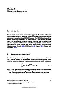
FIGURE 2. TETRA Platform: Development platform for RCS-based RoboCrane Controller (CRANE HOOK NOT SHOWN) CONVENTIONAL AMPS (RACK OF SIX)
ON-BOARD PC CONTROLLER
PAIR OF WINCHES/ CANAMPS (1 OF 3 PAIRS) REMOTE OPERATOR INTERFACE
PAIR OF PULLEYS ROUTING CABLES TO SUPPORT POINTS (1 OF 3 PAIRS) CARGO TO ACQUIRE
long-line suspended loads. This prototype system is called the Tetrahedral Robotic Apparatus (TETRA) (FIGURE 2). TETRA uses a similar Stewart Platform geometry with six cables driven by six winches. However, TETRA’s winches, amps, and computer controller are all mounted on the work platform instead of the supporting structure. This allows existing overhead lifting systems such as bridge cranes, boom cranes, and helicopters to be retrofitted. Also, the TETRA system is designed to allow the crane’s hook to provide most of the lifting force, while the additional six winches and cables provide controlled maneuverability during cargo acquisition and stabilization of the cargo during transfer. The six cables essentially act as coordinated taglines, providing 6 DOF control, thereby limiting spinning and swinging of the hook and cargo. The TETRA prototype will be used as the development platform for the RCS-based RoboCrane controller prior to implementation onto the 6m RoboCrane prototype.
modes:
• • • •
- Teach programing - Graphical off-line programing - Part programing
• Sensor based motion compensation. The RoboCrane’s available motion types include:
• • • • • • •
2.0 Current Control System The RoboCrane Integration Testbed (RIT) control system currently consists of a controller computer with graphical operator interface, a remote operator/observer interface, and graphical programmer [7]. All these components are connected through a network, as shown in the RoboCrane System Architecture Diagram (FIGURE 3). The RoboCrane control system functions in the following control
Master/slave Joystick input Operator panel input Preprogrammed trajectory following
Single joint Cartesian base frame (default) Cartesian platform frame Cartesian offset frame (tool center point) Constrained motions along vectors Rotations about vectors Single axis force control
2.1 The Controller The current RoboCrane Controller consists of a 64MHz Macintosh Quadra and an electronics rack electrically tied to one another through a Sensor Interface (FIGURE 3). Both the computer and the electronics rack house multiple components. The Sensor Interface converts the following
FIGURE 3. Current RoboCrane System Architecture Diagram Off-Line Programmer
SGI TGRIP
Controller with Operator Interface
Remote Operator/Observer Interface network
MacIntosh (68040) LabView
PC (80486) LabView
spaceball kinematics modem Video Servo 1-3 Servo 4-6 DMA MIO-A/D D/A Converter
Electronics Rack Signal PS Sensor Interface Power Amp 1 Power Amp 2 Power Amp 3 Power Amp 4 Power Amp 5 Power Amp 6 Emerg. Stop Isol. Transf. 1-3 Isol. Transf. 4-6
tension sensors Stewart Platform joystick
winch 1 encoder
winch 6 AC
pot
encoder pot
in
to be digitally fed back into the computer:
• six phase quadrature signal inputs from winch • • •
motor encoders (500 pulses per revolution) six analog 10-turn potentiometers (pot) on each winch motor through speed reducers six analog pots making up a Stewart platform (SP) joystick six analog output tension sensors into digital information.
The Sensor Interface outputs (not shown in figure 3) can be digital or analog. They are used to turn on/off linear actuators, tools and lights for a variety of applications such as gripping, grinding, and welding. The Macintosh outputs are analog signals from a 12 bit digital/analog converter board that provides input to the six power amplifiers. Pulse Width Modulated (20kHz) power amplifiers can be set in velocity or torque control modes. These are typically configured for velocity mode. For the operator interface, the RoboCrane control panel (FIGURE 4) provides interactive control over RoboCrane functions, settings, and status. Because the operators of these controllers are not expected to be computer literate and might wear protective gloves, a simple and intuitive graphic interface was developed using LabView software. Control modes and motion types can be activated or deactivated by computer mouse actions and/or touch screen actions. For direct manipulation of the FIGURE 4. Robocrane Control Panel
RoboCrane platform, a 6 DOF force sensing joystick (Spaceball) is input serially through the computer modem port and communicates at 19.2 kbaud.
2.2 Remote Operator/Observer Interface A Remote Operator/Observer Interface was developed to allow networked communications with the RoboCrane controller. This graphical interface consists of a touchscreen panel which looks similar to the actual RoboCrane controller panel. It communicates with the RoboCrane controller via ethernet and serves as a remote operator control station anywhere the network can reach. In addition, this remote interface can act simply as an observer of RoboCrane operations, without any control functionality. The interface’s front panel buttons allow a remote operator, with the proper permissions, to take control of RoboCrane functions or to simply act as a passive observer. The executable code for this Remote Operator/Observer Interface can be run on a computer located anywhere on the network.
2.3 The Off-Line Graphical Programmer The Off-Line Graphical Programmer allows for safe and easy generation of platform trajectories (move commands) along with the timely actuation of tools. The Graphical Programmer runs on a Silicon Graphics (SGI) computer
and controls the operation of a TGRIP (Teleoperative Graphical Robot Instruction Program) simulation of the RoboCrane workspace. The RoboCrane’s platform and tools are intuitively represented as three dimensional solid models. Graphical simulations of Robo-Crane motions, tool status, and other information is stored in a standard text file and is then made available to the RoboCrane through the network.
3.0 RCS-Based RoboCrane Control System In addition to maintaining the RoboCrane’s current control modes and capabilities, the proposed RCS-based RoboCrane Control System (FIGURE 5) contains several targeted improvements. Some examples are as follows:
• hierarchical, open system architecture with
2.4 Telepresence System
•
A telepresence system is currently being developed and integrated into the RoboCrane Integration Testbed. It will include a flexible manipulator, called EMMA (Easily Manipulated Mechanical Armatures). The EMMA arm will be attached to the work platform with a pan-tilt-vergence (PTV) head as an end-effector. Dual sets of stereo cameras (foveal and peripheral views) will be installed on the PTV head. These allow a remote operator to have full telepresence into the RoboCrane work volume during operation. The operator will wear a heads-up display to enable continuous visual contact along with access to RoboCrane controller operations.
2.5 System Complexity The RoboCrane controller consists of a complex assortment of over 900 electrical wires that can be difficult, tedious, and time-consuming to troubleshoot. The current configuration requires strong electrical signals to pass through long cables connecting the controller to motors, sensors, and tools. For example, the cables connecting the power amplifiers to the motors measure more than 25m in length. This type of electrical system complexity will be remedied in the RCS-based RoboCrane Control System.
•
standard control module interfaces separate user interface into each level of the controller more adaptable electronic design which scales well for larger systems
These and other enhancements will form a modular, reconfigurable control system that will allow the system to be easily optimized for particular applications.
3.1 Computer Platforms The proposed computer platforms for the RCS-based RoboCrane Control System differ from the current system. The Controller hardware will be based on PC-compatible machines running the Windows NT operating system with real-time extensions. This combination will support the RoboCrane’s computing requirements, while maintaining consistency with a de facto industry standard platform. Similarly, the graphical operator interface will be a C++ implementation running on a PC compatible/Windows NT machine. The Off-Line Graphical Programmer will remain on the SGI (running UNIX) due to heavy graphics and rendering requirements. All of these computer subsystems will be connected via ethernet.
FIGURE 5. Proposed RoboCrane System Architecture Diagram Off-Line Programmer SGI UNIX TGRIP Controller PC
Windows NT
GUI PC
kinematics control module templates RCS Libraries/directories CAN Interface
network
spaceball CAN winch 11 encoder tach CAN winch encoder tach Amp CAN 11 winch 1 encoder tach Amp CAN winch 1 encoder tach Amp CAN 1 winch Amp CAN 11 winch11 encoder encoder tach tach Amp Amp 1 Jog Pot.
Windows NT
Visual C++ Panel (replaces Labview panel)
3.2 Component Changes One major change to the physical components of the system will be the power amplifiers for the winches. In the proposed system, the same six winches will be driven by Controller Area Network amplifiers (CANAMP) instead of conventional power amplifiers. These CANAMPs will be located at each of the winches. The CANAMPs will communicate with the host computer through a CAN interface card residing within the Controller computer. The data transfer rate for the CAN system is up to 1 Mbit/ sec. for networks up to 40m long and can contain 0 to 8 bytes of data without segmentation. These CANAMPs will remove the need for RoboCrane’s existing Sensor Interface, power amplifiers, power supplies, and isolation transformers. In addition, an emergency stop system (not shown in the figure) will be independently connected to the six CANAMPs, thereby eliminating the need for a separate electronics rack. Most other major components, such as the winches, joystick and sensors (tension, encoder, potentiometer), will be incorporated into the proposed design. The addition of “jog pots” will be necessary for occasional direct axis control of each winch, because the amplifiers will be colocated with winches. Jog pots will be used during noncomputer controlled tasks such as calibration and cable replacement.
3.3 Hierarchical Controller Modules The core concept behind the RCS-based RoboCrane Controller architecture centers around a hierarchical decomposition of tasks required to perform a particular application (FIGURE 6) [9]. The basic decomposition of commands can be loosely thought of in terms of time needed to perform the action. That is, at the bottom most Servo Level,
time (t) can be considered instantaneous. As one traverses up the hierarchy, each command level requires roughly an order of magnitude greater time (10x) to perform its command.Therefore, the Primitive (Prim) Level would require roughly 10t, the Elemental-Move (E-Move) Level would require 100t, the Task Level would require 1000t, and so on. Similarly, the RCS model supports upward passing of sensor data as necessary for a particular module to perform its function. As each decomposed command is successfully performed (or not) a status is sent back up the hierarchy to the appropriate controller module at any given level. At the higher levels of the hierarchy, such as the Task Level, commands take longer to perform and status indications return less frequently than at the lower levels. While at the Servo Level, commands, status messages and sensor readings are carried out almost continually. In addition, the concept of a world model database is maintained so that any controller module may access a particular piece of information if and when it is necessary. For instance, the Workcell Level: Robocrane module might need to check the status of a gripper (functional or broken) before agreeing to perform some task that involves part manipulation. An essential part of an open system architecture is the definition and standardization of controller module interfaces. This is important because it allows developers of particular modules with enhanced capabilities or experimental algorithms to “plug” their module into the overall control system and test it seamlessly. In the case of the RCS-based RoboCrane controller, the Neutral Manufacturing Language (NML) [10] will be used to perform all communications between control modules.
FIGURE 6. RCS Task Decomposition for the RoboCrane’s Work Platform Motion TIME 10,000t
RoboCrane WM TD
Grip Grind Weld SP Platform Motion SP SP WM SP WM TD SP WM TD SP WM TD
Work Cell
EMMA Motion Quick Change SP WM TD WM TD TD SP Task Operator Interface
1,000t
SP
goal motion 100t
Trajectory Generator SP WM TD
Emove
path 10t
CAN Interface SP WM TD
Prim
joint goal t
CAN amp CAN amp SP CAN WM amp TD SP CAN WM amp TD SP CAN WM amp TD SP CAN WM amp TD SP WM TD SP WM TD
Servo
controller tension sensors encoders tension sensors encoders SP tension sensors SP encoders SP tension sensors SP encoders SP tension sensors SP encoders SP tension sensors SP encoders SP SP SP SP
tachometer tachometer SP tachometer SP tachometer SP tachometer SP tachometer SP SP
winch motors winch motors TD winch motors TD winch motors TD winch motors TD 1 winch motor TD TD
actuators/sensors
3.4 Task Narrative As an example, consider the task decomposition of a RoboCrane application such as welding (FIGURE 6). For the RoboCrane to perform a welding application, the RoboCrane’s Workcell Level:RoboCrane control module must receive a command to “weld a part.” This high level command could be generated by a Shop Level control module (not shown in the figure), just as a part was placed in the RoboCrane work volume. Alternatively, that same command could be issued via the operator interface for that level, as will be the case for the RoboCrane. The “weld a part” command is then decomposed by an intelligent Workcell Level:RoboCrane module which understands what tools are available and knows how to decompose the given command into its constituent elements. As a result, it passes down two simultaneous Task Level commands to its subordinates, Task Level: Platform Motion and Task Level: Weld. As the Task Level: Platform Motion module receives its command, it decomposes it into a series of goal motions and passes them down to the E-Move Level: Trajectory Generator module. This module understands the RoboCrane platform kinematics and can turn goal motions into an appropriate path. If the RoboCrane’s kinematics were changed or if a completely different robot were used, this is the only controller module that would need to be updated. The E-Move Level: Trajectory Generator module passes down path information that the Prim Level: CAN Interface module knows how to turn into joint goals for each Servo Level: CANAMP module. Then each Servo Level: CANAMP receives its goal information from above and interfaces directly with its specific hardware (a winch in this case). Each Servo Level: CANAMP sends incremental move commands to its winch and listens for feedback from associated sensors (encoder or tachometer). This way, the Servo Level: CANAMP closes the servo loop right at the winch, providing a rapid response. All these servo level actuators are synchronized by the levels above so that the resulting platform motion traces the intended robot trajectory. Meanwhile, the Task Level: Weld module has been waiting for the status of the platform motion to show that it is near the intended weld seam. The Task Level: Weld module may check the world model database to see if a particular point has been passed. Once that status is true, the Task Level: Weld module will begin to deploy the weld tip and at the appropriate time, power the welder on and off to create a synchronized welding path.
4.0 Integration Procedure The RCS-based RoboCrane controller will support the current RoboCrane control modes, motion types, and targeted improvements listed in section 3.0 above. However, it is being developed on the TETRA platform (FIGURE 2) prior to integration into the RoboCrane Testbed for several tactical reasons. First, it is preferable to maintain RoboCrane demonstrations of tools and applications while the
RCS-based controller is being developed. Second, because the TETRA and RoboCrane platforms differ slightly, adapting the controller to RoboCrane will provide a good first test of the controller’s modularity and portability. Third, TETRA’s compact design provides easy access to all hardware and will simplify development and testing of the new controller. TETRA’s current controller configuration consists of six conventional amplifiers driving each of its six winches. Feedback from each winch encoder and tachometer are input into an eight axis PMAC motion controller board housed within an onboard PC compatible computer. The onboard PC also houses a CANPC interface board, which sends digital signals through a “token ring” style network to each CANAMP located at each winch. TETRA’s current configuration is wired to allow easy switching between using the conventional amplifiers and the CANAMP system to power the winches. When the CANAMPs are in service, the servo motion control loop is implemented between the intelligent CANAMP and the winch, instead of sending motor feedback signals all the way to a centralized motion controller board. This will be particularly beneficial for systems such as RoboCrane where this length can be 30m or more. TETRA’s CANAMP system will provide a functional example of the reduced electronic design complexity that was mentioned previously. Both TETRA’s onboard controller and offboard operator interface computers will use the Windows NT operating system, supplemented with real-time extensions which provide a 1ms cycle time. The onboard controller will incorporate RCS templates, NML communication protocols, shared memory, and other concepts consistent with an RCS controller [9]. The graphical user interface will be developed in C++. NIST has contracted with an industry partner, Advanced Technology and Research Corp. (ATR), to work closely in development of the RCS-based RoboCrane Controller aimed at producing a commercially available system. ATR will provide control module development and consulting, similar to their efforts on NIST’s Enhanced Machine Controller [9], a 4-axis machine tool controller currently in use in a General Motors manufacturing facility.
5.0 Summary Both the RoboCrane and TETRA prototypes are based on the Stewart platform parallel-link manipulator. They use cables as the parallel links and winches as the actuators. They can control the position, velocity, and force of tools and heavy machinery in all six degrees of freedom (x, y, z, roll, pitch, and yaw). The current RoboCrane control system consists of a computer Controller, a Remote Operator/Observer Interface, and an Off-line Graphical Programmer connected by a network. The Controller itself can support a variety of control modes and motion types. The Remote Operator/Observer
Interface can be used from any computer located on the network. It allows for full remote control of all RoboCrane functionality or can be used simply to observe RoboCrane operations. Although the current RoboCrane controller is functional, it does not provide a standard, easily modifiable, open system, nor does it use a hierarchical control architecture. So, ISD is focusing on development of an RCS-based RoboCrane Control System that supports all the existing control modes and provides improvements. These include standardization of controller module interfaces, separate user interfaces, more efficient electronic design, and others. A commercially available Controller Area Network (CAN) is also being incorporated to allow tighter servo loop control and limit wiring complexity. The RCS-based RoboCrane Controller is being developed on the TETRA system to allow continued demonstration of the RoboCrane while controller work advances. TETRA’s control can easily switch between conventional amplifiers and CANAMPs to allow stepwise development of the controller. NIST has contracted with an industry partner (ATR) to work closely in development of the RCSbased RoboCrane controller with the intention of producing a commercially available system that could be readily reconfigured for different applications.
6.0 References [1] Albus, J., McCain, H., Lumia, R., “NASA/NBS Standard Reference Model for Telerobot Control System Architecture (NASREM),” NIST Technical Note 1235, National Institute of Standards and Technology, July, 1987. [2] Albus, J. S., Bostelman, R. V., Dagalakis, N. G., “The NIST ROBOCRANE, A Robot Crane,” Journal of Robotic Systems, July 1992. [3] Stewart, D., “A Platform with Six Degrees of Freedom,” Proceedings of the Inst. of Mechanical Engineering, Volume 180(15), Part I:371-386, 1965-1966 [4] Bostelman, R.V, Albus, J. S., et. al., “A Stewart Platform Lunar Rover,” Engineering Construction and Operations in Space IV Proceeding, Albuquerque, NM, Feb 26Mar. 3, 1994. [5] Bostelman, R., Albus, J., Dagalakis, N., Jacoff, A., “RoboCrane Project: An Advanced Concept for Large Scale Manufacturing,” Association for Unmanned Vehicles Systems International Proceedings., Orlando, FL, July 15-19, 1996. [6] Bostelman.R.V., Albus, J.S., “Stability of an Underwater Work Platform Suspended from an Unstable Reference,” Engineering in Harmony with the Ocean Proceedings, October 1993. [7] Dagalakis, N. G., Albus, J.S., Bostelman, R.V., Fiala,
J., “Development of the NIST Robot Crane Teleoperation Controller,” Robotics and Remote Handling Proceedings, Fifth Topical Meeting, Knoxville, TN, April 1993. [8] Bostelman, R.V., Albus, J.S., Dagalakis, N. G., “A Robotic Crane System Utilizing the Stewart Platform Configuration,” International Symposium on Robotics and Manufacturing Proceedings, Santa Fe, NM, November 1012, 1992. [9] Lumia, Ronald, “The Enhanced Machine Controller Architecture,” International Symposium on Robotics and Manufacturing Proceedings, Maui, HI, August 14-18, 1994. [10] Shackleford, Will, “The NML Programmer’s Guide,” http://isd.cme.nist.gov/proj/rcs.lib/nml.html, 1995.