Reactive Power Generation for Single-Phase. Transformerless Vehicle-to-Grid Inverters: A. Review and New Solutions. Ehsan Afshari1, Gholam Reza Moradi2, ...
Reactive Power Generation for Single-Phase Transformerless Vehicle-to-Grid Inverters: A Review and New Solutions Ehsan Afshari1, Gholam Reza Moradi2, Alireza Ramyar2, Ramin Rahimi2, Babak Farhangi3, Shahrokh Farhangi2 1
Department of Electrical and Computer Engineering, Northeastern University, Boston, MA, USA 2 Department of Electrical and Computer Engineering, University of Tehran, Tehran, Iran 3 Current Ways Inc, Los Angeles, CA, USA Although high frequency isolation is employed in V2G inverters, high frequency isolated converters can be prone to common mode and leakage current [36, 43]; moreover, the circulating currents between line and dc link increase losses in the line side inverters [44-46]. In order to reduce the common mode voltage and leakage current, transformer-less topologies separate the dc link from the utility grid during zero voltage vectors [47]. This improves inverter efficiency despite additional components needed in transformer-less topologies. H5 [48], HERIC [49], and Full-Bridge inverter with DCBypass (FB-DCB) [50] are among the popular topologies that have addressed the leakage current phenomena. Compared to traditional voltage source inverters e.g. H-bridge or full bridge, the novel transformer-less topologies promise improved efficiency and power quality [51-53].
Abstract— Vehicle to Grid (V2G) technology enables Battery Powered Vehicles including Electric and Plugin Hybrid Electric Vehicles as distributed Energy Storage for the smart grid. V2G inverters are advanced power converters that provide active and reactive bidirectional power flow between the grid and the onboard energy storage. A V2G power conditioner includes a high frequency isolated dc-dc converter and a two-quadrant voltage source inverter. This paper proposes application of the transformer-less inverters for V2G power conversion. Transformer-less inverters such as H5, HERIC, and FB-DCB are popular for Photovoltaic (PV) generation systems, offering high efficiency unidirectional power conversion at unity powerfactor. The high efficiency and superior performance of these topologies in reducing common mode and circulating currents are beneficial for V2G application; however, the reactive power generation of these topologies has not been investigated. In this paper, the reactive power generation capability of these topologies is investigated. Traditional modulation methods are evaluated for reactive power generation. Additionally, novel modulation methods are proposed for improved operation at non-unity power factors. The advantages and disadvantages of the modulation methods for each topology are explored through MATLAB simulations.
As mentioned earlier, V2G inverters will further contribute to the grid if they are capable of reactive power generation. Importantly, recent studies have indicated that reactive power generation of the on-board V2Gs does not affect the life-time and performance of the battery [54]. The capability of the transformer-less topologies as V2G inverters for reactive power generation, has not been studied. In this paper, the reactive power generation capability of the abovementioned converters is comprehensively explored. Moreover, new modulation methods are proposed to improve reactive power generation of these inverters. Finally, the advantages and disadvantages of the modulation methods are validated through simulation case studies in MATLAB\SIMULINK and summarized in a table to be easily compared.
Keywords— FB-DCB; H-Bridge; H5; leakage current; modulation methods; reactive power injection; single-phase power converter; transformerless inverters; V2G.
I. INTRODUCTION Electric Vehicles (EV) and Plug-in Hybrid EV (PHEV) provide zero and ultra-low emission transportation and novel functionalities [1-6]. The driving range of EVs has been extended and the manufacturing cost has been reduced owing to the recent advances in the battery technology [7, 8]. The growth of PHEVs and EVs as well as advancement of onboard energy storage along with the power conversion capability of the power electronics intensive vehicular systems are the key enabling factors in Vehicle to Grid (V2G) technology [9]. V2G contributes to ancillary services such as reactive power support and load balance [4, 10-23]. All EVs are equipped by onboard Level 1 or Level 2 chargers. Level 1 chargers are limited to single phase lines (1.9 kW), which is slower but more available. Level 2 chargers are connected to split-phase and three-phase grid; with a limit of up to 80kW, they are faster onboard chargers [1, 11, 24-26]. Bidirectional onboard power conditioners are two quadrant ac-dc converters; the ac side is connected to the grid and the dc side is connected to the battery [1, 27]. A popular topology includes a line side voltage source inverter [27-33] and a high frequency isolated dc-dc converter [34-41]. V2G power converters need to be powerdense, cost-effective, and efficient [42]; therefore, use of transformer-less inverters can be a promising solution.
978-1-5090-3953-1/$31.00 ©2017 IEEE
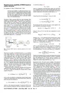
II. DESCRIPTION OF MODULATION METHODS FOR H-BRIDGE, H5, HERIC, AND FB-DCB The purpose of this paper is to investigate the reactive power compensation of H5, HERIC, and FB-DCB topologies, which can be potential solutions for the V2G applications. In this section, the topologies of these popular single-phase inverters are depicted. The earlier modulation methods for each of them, are analyzed in detail. Then, for each modulation method, reactive power injection capability of these topologies is studied. In addition, efficiency, leakage current waveform and amplitude, and switching losses are discussed and compared comprehensively. A. H-Bridge Topology Fig. 1 shows H-Bridge topology which is a commonlyused single-phase converter in power electronics applications, especially renewable energy systems and EVs. Bidirectional power flow is achieved by controlling the ac current reference versus the line voltage. Two main modulation methods have been proposed for this topology, bipolar and unipolar
69
are switched together at high frequency. In addition, during positive half cycles, S2 and S3 are OFF. In contrast, during negative half cycles, S2 is turned ON. In this situation, S3 and S5 are switched together at high frequency while S1 and S4 are OFF. As a result, in this modulation method, S1 and S2 are commutated at grid frequency and S3, S4, and S5 are switched at high frequency [59]. During positive half cycles, if S4 and S5 are ON, the voltage across the a and b terminals (Vab) is equal to Vdc. On the other hand, if S4 and S5 are OFF, Vab is equal to zero. Since the DC link is the highest voltage in the system, during zero vectors, D5 always blocks the leakage current at high side whether inverter is charge mode or discharge mode.
modulation [55]. In case of bipolar modulation method, shown in Fig. 2, all the switches are commutated at high frequency. S1 and S4 are switched together complementarily to S2 and S3. The output voltage variation is bipolar (from +Vdc to –Vdc) [55]. Accordingly, this strategy does not generate zero voltage states. In case of unipolar modulation method, however, since there are two mirrored references, the output voltage variation is unipolar (from +Vdc to zero and from zero to –Vdc) [55, 56]. The switching algorithm of the unipolar modulation method is illustrated in Fig. 3. B. H5 Topology Single-phase H5 inverter is based on H-Bridge inverter which is patented by SMA to mitigate the leakage current problem in transformer-less PV systems [48]. In this topology, as shown in Fig. 4, an extra switch is added between dc-link capacitor and the bridge. This additional switch separates the DC side from the grid side during zero voltage states, which is an effective solution to reduce the leakage current in transformer-less systems [57, 58]. Similar to H-bridge topology, this converter is able to operate for bidirectional power flow. C1
S1
D1 S2
D2
A
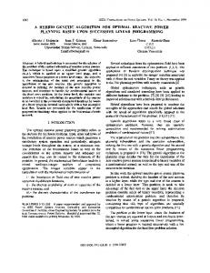
The shortcoming of this modulation method is that it cannot handle reactive power. In order to clarify the problem, it is assumed that the grid voltage is in the positive half cycle. Thus, Vab is equal to either zero or Vdc. Fig. 6(a) and (b) show the performance of the converter when the power factor is equal to 1. As can be seen in Fig. 6(a), Vab has a positive value and S1, S4, and S5 conduct the current (Ia) in the positive direction (current is flowing from the converter toward the grid as shown in Fig. 6(a)). When Vab is equal to zero, S4 and S5 are OFF, and S1 and D2 conduct the positive current. In contrast, if the power factor is not unity, during some intervals the grid voltage is positive and the current is negative, and vice versa, as shown in Fig. 6(e). Fig. 6(c) and (d) demonstrate the performance of H5 for generating reactive power. The problem appears when Vab is supposed to be zero. In this situation, since the current is negative, there is no path for the current to flow, as shown in Fig. 6(d). The reason is that the current has the opposite direction of the anti-parallel diode D2. Therefore, the current find a path through D1, D4, and D5 and produces positive level instead of zero level at the inverter terminals. Thus, the injected current gets highly distorted during zero point crossings, until the polarity of the current becomes similar to the grid voltage.
L1
Vdc
Grid L2
B
C2 S3
D3 S4
D4
Fig. 1. H-Bridge topology.
D5
C1
S5 S1
D1 S2
D2
a
L1
Vdc
Fig. 2. Switching algorithm of bipolar modulation method for H-Bridge.
Grid
C2
L2
b S3
D3 S4
D4
Fig. 4. H5 topology.
Fig. 3. Switching algorithm of unipolar modulation method for H-Bridge.
Two modulation methods have been proposed for this topology. In the earlier modulation method, as depicted in Fig. 5, during positive half cycles, S1 is turned ON and S4 and S5
Fig. 5. Switching algorithm of the first modulation method for H5 topology.
70
Where the voltage is positive while the current is negative
(e)
Fig. 6. Current path for H5 topology with traditional modulaiton when Vg>0, a) when Vab=Vdc (Unity power factor), b) when Vab=0 (Unity power factor), c) when Vab=Vdc (Non-unity power factor), (d) when Vab=0 (Non-unity power factor), (e) Voltage and current showing the phase shift.
Fig. 7. Current path for H5 topology with the proposed modulaiton method when Vg>0 and power factor is not one. a) when Vab=Vdc, b) when Vab=0.
In this paper, novel modulation methods are proposed enabling reactive power generation by providing a proper path for the current flowing in the reverse direction when reactive power is injected. The proposed method maintains the output current THD in an acceptable range. Moreover, leakage current will stay within the allowed limit. In this section, the proposed method for H5 is described. For the example discussed in the previous section, the grid voltage is in positive half cycle (S1 is ON). When Vab is supposed to be equal to Vdc, the same algorithm can be applied and S4 and S5 are turned ON. In this case, anti-parallel diodes, D1, D4, and D5, conduct the negative current. The current circulates through the capacitors, since a diode is placed in series with the DC source. However, the problem appears when zero vector should be produced. In this situation, S2 needs to be turned ON to produce zero voltage in the terminals by providing a path for the current. Therefore, there is a path for the negative current to flow through D1 and S2, as shown in Fig. 7(b). The switching algorithm of the novel modulation method is depicted in Fig. 8.
C. HERIC Topology HERIC topology is shown in Fig. 9. As can be observed, two back-to-back switches, S+ and S-, are added to isolate the dc side from the grid side during zero voltage vectors. At active power modes, HERIC operates similar to the H-bridge and is able to transfer bidirectional power In [49], a modulation method is proposed for HERIC topology, which is not able to generate reactive power; this is the same problem that H5 topology suffers from. This switching method is depicted in Fig. 10. In this method, S1-S4 are switched at high frequency, while S+ and S- are commutated at grid frequency. S+ is turned ON during positive half cycles of the grid voltage, whereas S- is turned ON during negative half cycles. S1 and S4 are commutated at high frequency during positive half cycles, while S2 and S3 are switched during negative half cycles. In this paper, a novel modulation method has been proposed, as illustrated in Fig. 11, to enable this topology to inject reactive power into the grid. In the novel method, during the intervals that the grid voltage and injected current do not have the same polarity, switches S+ and S- are commutated at high frequency. S+ is switched complimentarily to S2 and S3, while S- is commutated complimentarily to S1 and S4. Switches S+ and S- are only switched at high frequency in non-utility power factors where the voltage and current have opposite polarity; performance of these switches is similar to the traditional modulation method in unity power factor. S1 C1
Fig. 8. Switching algorithm of the novel modulation method for H5 topology
D1 S2
D2
L1
a D-
S+
S-
D+
Vdc
Grid b
C2 S3
Fig. 9. HERIC topology.
71
D3 S4
D4
L2
Fig. 13. Switching algorithm of the first modulation method for FB-DCB topology.
Fig. 10. Switching algorithm of the traditional modulation method for HERIC topology.
Fig. 14. Switching algorithm of the second modulation method for FB-DCB topology.
Fig. 11. Switching algorithm of the novel modulation method for HERIC topology.
A novel modulation method is proposed to improve the efficiency and balance switching losses as well as enabling reactive power injection. In this modulation method, S1 and S4 are turned ON in positive half cycles and S2 is commutated at switching frequency complementarily to S5 and S6. In contrast to the second method, in the positive half cycles, only three switches are commutated at the switching frequency. In the negative half cycles, S2 and S3 are turned ON and S1 is commutated at the switching frequency complementarily to S5 and S6. Moreover, a rotating method is utilized in this method to balance switching losses among switches in the bridge. To do so, during positive half cycles, in one cycle, S2 is switched at high frequency, and in the next cycle S3 would be switched at high frequency. A similar strategy is utilized during negative half cycles for S1 and S4. Fig. 15 shows the switching algorithm of this strategy.
D. FB-DCB Topology Fig. 12 shows the FB-DCB topology which is a modified classical H-Bridge and introduced by Ingeteam [60]. This topology is also a bidirectional ac-dc converter based on Hbridge inverter and can be used for energy storage applications. This topology has two extra switches and diodes, which are used to separate the DC side from the grid side during zero voltage states. In fact, these switches are added to H-Bridge topology in order to alleviate the leakage current issue by providing a freewheeling path. These solutions are applied to reduce the leakage current of transformer-less PV systems and enhance the total efficiency by prevention of reactive power exchange between the line filter L and dc link capacitors C1 and C2. Three main modulation methods have been proposed for this topology. In the first conventional modulation method, S1 and S4 are turned ON in positive half cycles. On the other hand, S2 and S3 are turned ON in negative half cycles. Thus, S1, S2, S3, and S4 are switched at grid frequency. In order to produce zero voltage states in both positive and negative half cycles, S5 and S6 are commutated at the switching frequency [55]. The switching algorithm of this modulation method is shown in Fig. 13. In the second modulation method, S1 and S4 are turned ON in positive half cycles. During positive half cycles, S2 and S3 are switched together at high frequency complementarily to S5 and S6. In contrast, during negative half cycles, S2 and S3 are turned ON and S1 and S4 are commutated together at switching frequency complementarily to S5 and S6 [61]. The switching algorithm of the second modulation method is illustrated in Fig. 14.
Fig. 15. Switching algorithm of the novel modulation method for FB-DCB topology.
III. SIMULATION RESULTS Reactive power in VAR is the product of the RMS voltage and current and depends on the phase shift between output voltage and current of the inverter. The phase shift between output voltage and current means that in some parts, their polarities are inverse. Therefore, in order to be able to handle reactive power, a possible path for passing the freewheeling current must be provided to keep the output current purely sinusoidal. Otherwise, if there is no possible path for the reverse current, the switching sequences would be disturbed. In this situation, output current would be highly distorted and THD would deteriorate. A Proportional-Resonant (PR)
D5 S5 C1
S1 D+
D1 S2
D2
L1
A
Vdc
Grid L2
D-
C2 S6
B S3
D3 S4
D4
D6
Fig. 12. FB-DCB topology.
72
controller is employed for adjusting the PWM references of the converter topologies [62-64]. Therefore, in order to simulate and study the reactive power injection capability of these topologies, the power factor is assumed to be 0.5. The system parameters are listed in Table I.
B. H5 Topology The performance of this modulation method is compared with the proposed modulation in Fig. 19 and Fig. 20. As can be seen in Fig. 19, during the zero crossings, the current and voltage do not have the same polarity and the current is distorted. As the phase shift between the voltage and current increases, the zero point crossings become worse. The THD for traditional modulation method is 7.96%.
TABLE I. TECHNICAL SPECIFICATIONS OF THE SYSTEM. Parameters Value 1800 Nominal Power (VA) 220 Grid Voltage (V) 50 Grid Frequency (Hz) 5 L Filter (mH) 20 Switching Frequency (kHz) 18 Parasitic Capacitor (nF) 450 DC Link Voltage (V)
On the other hand, in the second modulation method, since a possible path is provided for the reverse current, the inverter is able to generate reactive power without distortion of current as shown in Fig. 20(a). In addition, according to Fig. 20(b), the leakage current problem is solved, because the additional switch separates the DC side from the grid side during zero voltage states. Thus, the novel modulation method not only has the capability to inject reactive power with an acceptable THD, but also its leakage current passes grid standards.
A. H-Bridge Topology Fig. 16 demonstrates the grid voltage, which is considered to be the same for all simulation studies. Simulation results of the bipolar modulation method is shown in Fig. 17. As shown in Fig. 17(a), the H-Bridge topology has the capability to inject reactive power, since the injected current in case of reactive power generation, is completely sinusoidal and THD is acceptable. In addition, the leakage current amplitude is acceptable, regarding the VDE 0126-1-1 standard. However, the shortcoming of this modulation method is its low efficiency in comparison to unipolar modulation method. The efficiency for this strategy is around 96.1% in case of injecting nominal power. Simulation results of unipolar modulation method is depicted in Fig. 18. According to Fig. 18(a), this strategy has the capability to inject reactive power because of the acceptable value of output current THD, which is 5.34%. However, in case of unipolar modulation, the leakage current is a big concern for this topology, which makes it inappropriate for transformer-less systems. As shown in Fig. 18(b) the amplitude of leakage current is around 2A with high frequency components which violates VDE 0126-1-1.
Fig. 19. Simulation Results of the first modulation method for H5 topology. (a) Line Current. (b) Leakage Current. The current is distorted during zero crossings, where the grid voltage and current do not have the same polarity.
Fig. 20. Simulation Results of the novel modulation method for H5 topology. (a) Line Current. (b) Leakage Current. The injected current is completely smooth during zero crossings, wince proper path is established for the freewheeling current.
Fig. 16. The grid voltage connected to the inestigated inverters.
C. HERIC Topology A modulation method for this topology has been proposed in the literature, which is not capable to handle reactive power, as shown in Fig. 21(a). The zero crossing points are shown in red circles. In case of reactive power generation, the output current waveform is similar to the first method of H5. On the other hand, in the novel method, since a possible path is established for the reverse current, the inverter is able to generate reactive power without a current distortion at zero crossings; the waveform is shown in Fig. 21(b). With the proposed method, this converter can inject positive current when the voltage across the terminals of the converter is negative, and vice versa. The leakage current problem is addressed in this topology when either of the modulation methods is employed, as can be seen in Fig. 22(a) and Fig. 22(b).
Fig. 17. Simulation results of biplar modulation method for H-Bridge topology. (a) Line Current. (b) Leakage current.
Fig. 18. Simulation results of unipolar modulation method for H-Bridge topology. (a) Line Current. (b) Leakage Current.
73
Fig. 24. Simulation Results of the second modulation method for FB-DCB topology. (a) Line Current. (b) Leakage Current.
Fig. 21. Simulation results of the HERIC topology. (a) First modulation method [49] (THD=7.08%). (b) Proposed modulation method (THD=3.44%). Red elipses in (a) proves that the switching is distrubed for operation at non-unity power factor which is completely resolved in (b).
Fig. 25. Simulation Results of the novel modulation method for FB-DCB topology. (a) Line Current. (b) Leakage Current.
IV. CONCLUSION In this paper, reactive power injection capability of the popular single-phase transformer-less topologies including HBridge, H5, HERIC, and FB-DCB were investigated. HBridge topology with unipolar modulation method can generate reactive power; however, suffers from the leakage current issue. H-Bridge topology with bipolar modulation method does not suffer from leakage current issue; on the other side, the efficiency is relatively low. For FB-DCB, [7] had proposed a modulation method that works for reactive power; however, the efficiency is low. Authors further improved this method by balancing losses between the inverter switches leading to a better efficiency as shown in Table II. The modulation methods proposed for H5 and HERIC topologies in earlier works are not capable to inject reactive power; the output current is highly distorted when the output current is not in-phase with the grid voltage. We proposed a modulation method that improves the output current THD when reactive power is generated. Table II and Fig. 26 summarizes the comparison between the discussed modulation methods for reactive power generation of each converter. According to the provided case studies, H5, HERIC, and FB-DCB topologies with the new modulation methods have demonstrated superior performance when the grid-connected inverter injects reactive power.
Fig. 22. Leakage current of the HERIC topology. (a) First modulation method. (b) Proposed modulation method.
D. FB-DCB Topology Fig. 23 presents the simulation results of the first conventional method. As depicted in Fig. 23(a), this modulation method is not suitable for non-unity power factors, since the current is disturbed during zero crossing points. The distorted points are shown in red circles. On the other hand, as Fig. 24(a) shows, the second modulation method is capable to inject reactive power with an acceptable THD. This is achieved by turning ON proper switches during the intervals that the injected current and grid voltage polarity are reverse. However, four switches are switched at high frequency, which can increase the switching losses. Thus, a novel modulation method has been proposed to improve the efficiency and enable reactive power injection. As depicted in Fig. 25(a), since the output current THD is acceptable, this novel strategy has the capability to inject reactive power. In addition, since this method has balanced switching losses among switches in H-Bridge and only three switches are commutated at high frequency, it is more suitable for reactive power injection. Moreover, the leakage current waveform and amplitude is the same in all modulation methods proposed for this topology.
120 100
Output Current THD 96.1 96.5 98.1 98.4
Conversion Efficiency 97.9 98.2 97.3 97.8
98.1
80 60
3.5
3.41
Second Method
Proposed Method
8.02
3.44
7.08
3.43
7.96
5.34
20
Fig. 23. Simulation Results of the first modulation method for FB-DCB topology. (a) Line Current. (b) Leakage Current.
6.04
40
HERIC
First Method
Proposed Method
Proposed Method
H5
First Method
H-Bridge
First Method
Unipolar
Bipolar
0
FB-DCB
Fig. 26. Comparison of the performance of the single-phase converters in terms of output current THD and efficiency.
74
TABLE II.
COMPARISION OF PERFORMANCE OF POPULAR SINGLE-PHASE TRANSFORMERLESS TOPOLOGIES FOR V2G POWER CONVERTERS.
Topology
Modulation Method
THD (%)
H-Bridge
Bipolar [55] Unipolar [55] First Method [48] Proposed Method First Method [49] Proposed Method First Method [55] Second Method [65] Proposed Method
6.04 5.34 7.96 3.43 7.08 3.44 8.02 3.50 3.41
H5 HERIC FB-DCB
Reactive Power Injection Yes Yes No Yes No Yes No Yes Yes
High Frequency Switching
Efficiency
Balanced Switching Losses
Four Switches Four Switches Two Switches Three Switches Two Switches Three Switches Two Switches Four Switches Three Switches
0.961 0.965 0.981 0.984 0.979 0.982 0.973 0.978 0.981
Yes Yes No No No Yes Yes No Yes
[16] M. Falahi, C. Hung-Ming, M. Ehsani, X. Le, and K. L. Butler-Purry, "Potential Power Quality Benefits of Electric Vehicles," Sustainable Energy, IEEE Transactions on, vol. 4, pp. 1016-1023, 2013. [17] P. A. Mendoza-Araya, P. J. Kollmeyer, and D. C. Ludois, "V2G integration and experimental demonstration on a lab-scale microgrid," in Energy Conversion Congress and Exposition (ECCE), 2013 IEEE, 2013, pp. 5165-5172. [18] J. Farhang, M. Eydi, B. Asaei, and B. Farhangi, "Flexible strategy for active and reactive power control in grid connected inverter under unbalanced grid fault," in Electrical Engineering (ICEE), 2015 23rd Iranian Conference on, 2015, pp. 1618-1623. [19] M. Eydi, J. Farhang, B. Asaei, and B. Farhangi, "Improving battery performance in hybrid energy storage system of PMSG wind turbine by variable filter cut off frequency," in Power Electronics and Drive Systems Technologies Conference (PEDSTC), 2016 7th, 2016, pp. 285290. [20] B. Farhangi and K. Butler-Purry, "Transient study of DC zonal electrical distribution system in next generation shipboard integrated power systems using PSCAD™," in North American Power Symposium (NAPS), 2009, 2009, pp. 1-8. [21] E. Afshari, B. Farhangi, Y. Yang, and S. Farhangi, "A Low-Voltage Ride-Through Control Strategy for Three-Phase Grid-Connected PV Systems " presented at the IEEE Power and Energy Conference at Illinois (PECI), Illinois, USA, 2017. [22] E. Afshari, G. R. Moradi, Y. Yang, B. Farhangi, and S. Farhangi, "A Review on Current Reference Calculation of Three-Phase GridConnected PV Converters under Grid Faults," presented at the IEEE Power and Energy Conference at Illinois (PECI), Illinois, USA, 2017. [23] S. Ouni, M. R. Zolghadri, M. khodabandeh, M. Shahbazi, J. Rodriguez, H. O. Mirzamani, et al., "Improvement of Post-Fault Performance of Cascaded H-bridge Multilevel Inverter," IEEE Transactions on Industrial Electronics, vol. PP, pp. 1-1, 2016. [24] B. Farhangi, H. A. Toliyat, and A. Balaster, "High impedance grounding for onboard plug-in hybrid electric vehicle chargers," in Power Engineering, Energy and Electrical Drives (POWERENG), 2013 Fourth International Conference on, 2013, pp. 609-613. [25] SAE, "SAE J1772™: SAE Electric Vehicle and Plug in Hybrid Electric Vehicle Conductive Charge Couple," ed, Feb. 2012. [26] S. Haghnazari, M. Khodabandeh, and M. R. Zolghadri, "Fast fault detection method for modular multilevel converter semiconductor power switches," IET Power Electronics, vol. 9, pp. 165-174, 2016. [27] B. Farhangi, "A novel modified deadbeat controller for vehicle to grid application," in Power Electronics, Drives Systems & Technologies Conference (PEDSTC), 2015 6th, 2015, pp. 47-52. [28] X. Zhou, S. Lukic, S. Bhattacharya, and A. Huang, "Design and control of grid-connected converter in bi-directional battery charger for plug-in hybrid electric vehicle application," in Vehicle Power and Propulsion Conference, 2009. VPPC'09. IEEE, 2009, pp. 1716-1721. [29] M. C. Kisacikoglu, M. Kesler, and L. M. Tolbert, "Single-Phase OnBoard Bidirectional PEV Charger for V2G Reactive Power Operation," IEEE Transactions on Smart Grid, vol. 6, pp. 767-775, 2015. [30] M. Hamzeh, S. Farhangi, and B. Farhangi, "A new control method in PV grid connected inverters for anti-islanding protection by impedance monitoring," in Control and Modeling for Power Electronics, 2008. COMPEL 2008. 11th Workshop on, 2008, pp. 1-5. [31] B. Farhangi and S. Farhangi, "Application of Z-Source Converter in Photovoltaic Grid-Connected Transformer-Less Inverter," Electrical Power Quality and Utilisation, Journal, vol. 12, pp. 41-45, 2006. [32] M. Liserre, F. Blaabjerg, and A. Dell'Aquila, "Step-by-step design procedure for a grid-connected three-phase PWM voltage source
REFERENCES [1] B. Farhangi, "Power Conditioning for Plug-In Hybrid Electric Vehicles," Texas A&M University, 2014. [2] S. Wencong, H. Eichi, Z. Wente, and C. Mo-Yuen, "A Survey on the Electrification of Transportation in a Smart Grid Environment," Industrial Informatics, IEEE Transactions on, vol. 8, pp. 1-10, 2012. [3] B. Farhangi and H. Toliyat, "A Novel Vehicular Integrated Power System Realized with Multi-port Series Ac Link Converter," in Applied Power Electronics Conference and Exposition, 2015. APEC 2015. 30th Annual IEEE, 2015, pp. 1353-1359. [4] A. Ramezani, S. Farhangi, H. Iman-Eini, and B. Farhangi, "High efficiency wireless power transfer system design for circular magnetic structures," in Power Electronics and Drive Systems Technologies Conference (PEDSTC), 2016 7th, 2016, pp. 565-570. [5] G. Carli and S. S. Williamson, "Technical Considerations on Power Conversion for Electric and Plug-in Hybrid Electric Vehicle Battery Charging in Photovoltaic Installations," Power Electronics, IEEE Transactions on, vol. 28, pp. 5784-5792, 2013. [6] E. S. Dehaghani and S. S. Williamson, "On the inefficiency of vehicleto-grid (V2G) power flow: Potential barriers and possible research directions," in Transportation Electrification Conference and Expo (ITEC), 2012 IEEE, 2012, pp. 1-5. [7] S. Haghbin, S. Lundmark, M. Alakula, and O. Carlson, "Grid-connected integrated battery chargers in vehicle applications: Review and new solution," IEEE Transactions on Industrial Electronics, vol. 60, pp. 459473, 2013. [8] S. Jafarishiadeh, M. Farasat, and A. M. Bozorgi, "Modeling, analysis and design of an undersea storage system," in 2016 IEEE Energy Conversion Congress and Exposition (ECCE), 2016, pp. 1-6. [9] M. Mohebbi, M. L. McIntyre, and J. Latham, "Vehicle to grid utilizing a backstepping controller for bidirectional full-bridge converter and five level active neutral point inverter," in 2015 IEEE 16th Workshop on Control and Modeling for Power Electronics (COMPEL), 2015, pp. 17. [10] "IEEE Application Guide for IEEE Std 1547, IEEE Standard for Interconnecting Distributed Resources with Electric Power Systems," in IEEE Std 1547.2-2008, ed, 2009, pp. 1-207. [11] M. Yilmaz and P. T. Krein, "Review of battery charger topologies, charging power levels, and infrastructure for plug-in electric and hybrid vehicles," IEEE Transactions on Power Electronics, vol. 28, pp. 21512169, 2013. [12] F. R. Islam, H. R. Pota, and A. B. M. Nasiruzzaman, "PHEV's park as a virtual active filter for HVDC networks," in Environment and Electrical Engineering (EEEIC), 2012 11th International Conference on, 2012, pp. 885-890. [13] A. K. Verma, B. Singh, and D. T. Shahani, "Grid to vehicle and vehicle to grid energy transfer using single-phase bidirectional AC-DC converter and bidirectional DC-DC converter," in Energy, Automation, and Signal (ICEAS), 2011 International Conference on, 2011, pp. 1-5. [14] M. C. Kisacikoglu, B. Ozpineci, and L. M. Tolbert, "Examination of a PHEV bidirectional charger system for V2G reactive power compensation," in Applied Power Electronics Conference and Exposition (APEC), 2010 Twenty-Fifth Annual IEEE, 2010, pp. 458465. [15] Y. Du, X. Zhou, S. Bai, S. Lukic, and A. Huang, "Review of non-isolated bi-directional DC-DC converters for plug-in hybrid electric vehicle charge station application at municipal parking decks," in Applied Power Electronics Conference and Exposition (APEC), 2010 Twenty-Fifth Annual IEEE, 2010, pp. 1145-1151.
75
converter," International Journal of Electronics, vol. 91, pp. 445-460, 2004. [33] M. H. Jahanbakhshi, B. Asaei, and B. Farhangi, "A novel deadbeat controller for single phase PV grid connected inverters," in Electrical Engineering (ICEE), 2015 23rd Iranian Conference on, 2015, pp. 16131617. [34] B. Farhangi and H. A. Toliyat, "Piecewise Linear Model for Snubberless Dual Active Bridge Commutation," Industry Applications, IEEE Transactions on, vol. 51, pp. 4072-4078, 2015. [35] B. Farhangi and H. A. Toliyat, "Modeling and Analyzing Multiport Isolation Transformer Capacitive Components for Onboard Vehicular Power Conditioners," Industrial Electronics, IEEE Transactions on, vol. 62, pp. 3134-3142, 2015. [36] B. Farhangi and H. A. Toliyat, "Modeling Isolation Transformer Capacitive Components in a Dual Active Bridge Power Conditioner," in Energy Conversion Congress and Exposition (ECCE), 2013 IEEE, 2013, pp. 5476-5480. [37] S. Inoue and H. Akagi, "A Bidirectional Isolated DC to DC Converter as a Core Circuit of the Next-Generation Medium-Voltage Power Conversion System," Power Electronics, IEEE Transactions on, vol. 22, pp. 535-542, 2007. [38] D. de Souza Oliveira, C. E. de Alencar e Silva, B. Torrico, x, R. P., F. L. Tofoli, et al., "Analysis, Design, and Experimentation of a Double Forward Converter With Soft Switching Characteristics for All Switches," Power Electronics, IEEE Transactions on, vol. 26, pp. 21372148, 2011. [39] T. F. Wu, Y. C. Chen, J. G. Yang, Y. C. Huang, S. S. Shyu, and C. L. Lee, "1.5 kW isolated bi-directional DC-DC converter with a flyback snubber," in Power Electronics and Drive Systems, 2009. PEDS 2009. International Conference on, 2009, pp. 164-169. [40] O. C. Onar, J. Kobayashi, D. C. Erb, and A. Khaligh, "A Bidirectional High-Power-Quality Grid Interface With a Novel Bidirectional Noninverted Buck-;Boost Converter for PHEVs," Vehicular Technology, IEEE Transactions on, vol. 61, pp. 2018-2032, 2012. [41] O. C. Onar and A. Khaligh, "A Novel Integrated Magnetic Structure Based DC/DC Converter for Hybrid Battery/Ultracapacitor Energy Storage Systems," Smart Grid, IEEE Transactions on, vol. PP, pp. 1-1, 2011. [42] V. Monteiro, J. G. Pinto, and J. L. Afonso, "Operation Modes for the Electric Vehicle in Smart Grids and Smart Homes: Present and Proposed Modes," IEEE Transactions on Vehicular Technology, vol. 65, pp. 10071020, 2016. [43] L. Palma, M. H. Todorovic, and P. N. Enjeti, "Analysis of CommonMode Voltage in Utility-Interactive Fuel Cell Power Conditioners," Industrial Electronics, IEEE Transactions on, vol. 56, pp. 20-27, 2009. [44] B. Farhangi and S. Farhangi, "Comparison of z-source and boost-buck inverter topologies as a single phase transformer-less photovoltaic gridconnected power conditioner," in Power Electronics Specialists Conference, 2006. PESC'06. 37th IEEE, 2006, pp. 74-79. [45] R. Rahimi, E. Afshari, B. Farhangi, and S. Farhangi, "Optimal placement of additional switch in the photovoltaic single-phase grid-connected transformerless full bridge inverter for reducing common mode leakage current," in Energy Conversion (CENCON), 2015 IEEE Conference on, 2015, pp. 408-412. [46] R. Teodorescu, M. Liserre, and P. Rodriguez, "Grid converters for photovoltaic and wind power systems," ed: John Wiley & Sons, 2011. [47] G. R. Moradi, E. Afshari, R. Rahimi, B. Farhangi, and S. Farhangi, "Improvement of the modulation method for single-phase transformerless photovoltaic conergy inverter for reactive power injection capability," in 2016 24th Iranian Conference on Electrical Engineering (ICEE), 2016, pp. 1312-1317. [48] F. G. Matthias Victor, Sven Bremicker, Uwe Hubler, "Method of converting a direct current voltage from a source of direct current voltage, more specifically from a photovoltaic couse of direct current voltage, into a alternating current voltage ", 2005.
[49] H. Schmidt, C. Siedle, and J. Ketterer, "DC/AC converter to convert direct electric voltage into alternating voltage or into alternating current," ed: Google Patents, 2006. [50] R. Gonzalez, J. Coloma, L. Marroyo, J. Lopez, and P. Sanchis, "Singlephase inverter circuit for conditioning and converting DC electrical energy into AC electrical energy," Patent PCT No. WO, vol. 15298, p. A1, 2008. [51] S. Farhangi, B. Vafakhah, B. Farhangi, P. Kanaan, and S. Maneshipoor, "A 5kW grid-connected system with totally home-made components in Iran," in 19th European Photovoltaic Solar Energy Conference and Exhibition, 2004, pp. 2988-2991. [52] R. Rahimi, B. Farhangi, and S. Farhangi, "New topology to reduce leakage current in three-phase transformerless grid-connected photovoltaic inverters," in Power Electronics and Drive Systems Technologies Conference (PEDSTC), 2016 7th, 2016, pp. 421-426. [53] O. Lopez, R. Teodorescu, F. Freijedo, and J. DovalGandoy, "Leakage current evaluation of a singlephase transformerless PV inverter connected to the grid," in Applied Power Electronics Conference, APEC 2007-Twenty Second Annual IEEE, 2007, pp. 907-912. [54] M. C. Kisacikoglu, B. Ozpineci, and L. M. Tolbert, "EV/PHEV bidirectional charger assessment for V2G reactive power operation," IEEE Transactions on Power Electronics, vol. 28, pp. 5717-5727, 2013. [55] R. Teodorescu, M. Liserre, and P. Rodriguez, Grid converters for photovoltaic and wind power systems vol. 29: John Wiley & Sons, 2011. [56] M. Calais, J. Myrzik, T. Spooner, and V. G. Agelidis, "Inverters for single-phase grid connected photovoltaic systems-an overview," in Power Electronics Specialists Conference, 2002. pesc 02. 2002 IEEE 33rd Annual, 2002, pp. 1995-2000. [57] B. Yang, W. Li, Y. Gu, W. Cui, and X. He, "Improved transformerless inverter with common-mode leakage current elimination for a photovoltaic grid-connected power system," Power Electronics, IEEE Transactions on, vol. 27, pp. 752-762, 2012. [58] Y. Gu, W. Li, Y. Zhao, B. Yang, C. Li, and X. He, "Transformerless inverter with virtual DC bus concept for cost-effective grid-connected PV power systems," Power Electronics, IEEE Transactions on, vol. 28, pp. 793-805, 2013. [59] T.-F. Wu, C.-L. Kuo, K.-H. Sun, and H.-C. Hsieh, "Combined unipolar and bipolar PWM for current distortion improvement during power compensation," Power Electronics, IEEE Transactions on, vol. 29, pp. 1702-1709, 2014. [60] S. R. Gonzalez, C. J. Coloma, P. L. Marroyo, T. J. Lopez, and G. P. Sanchis, "Single-phase inverter circuit for conditioning and converting dc electrical energy into ac electrical energy," ed: Google Patents, 2008. [61] R. González, J. López, P. Sanchis, and L. Marroyo, "Transformerless inverter for single-phase photovoltaic systems," Power Electronics, IEEE Transactions on, vol. 22, pp. 693-697, 2007. [62] M. Khodabandeh, M. R. Zolghadri, and N. Noroozi, "A new t-type direct AC/AC converter," in The 6th Power Electronics, Drive Systems & Technologies Conference (PEDSTC2015), 2015, pp. 247-252. [63] M. Khodabandeh, M. R. Zolghadri, M. Shahbazi, and N. Noroozi, "Ttype direct AC/AC converter structure," IET Power Electronics, vol. 9, pp. 1426-1436, 2016. [64] A. M. Bozorgi, M. S. Chayjani, R. M. Nejad, and M. Monfared, "Improved grid voltage sensorless control strategy for railway power conditioners," IET Power Electronics, vol. 8, pp. 2454-2461, 2015. [65] E. Afshari, R. Rahimi, B. Farhangi, and S. Farhangi, "Analysis and modification of the single phase transformerless FB-DCB inverter modulation for injecting reactive power," in 2015 IEEE Conference on Energy Conversion (CENCON), 2015, pp. 413-418.
76